Cutting a board
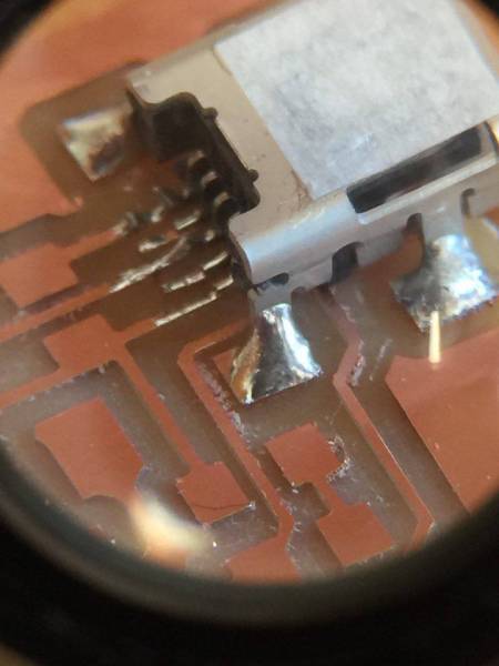
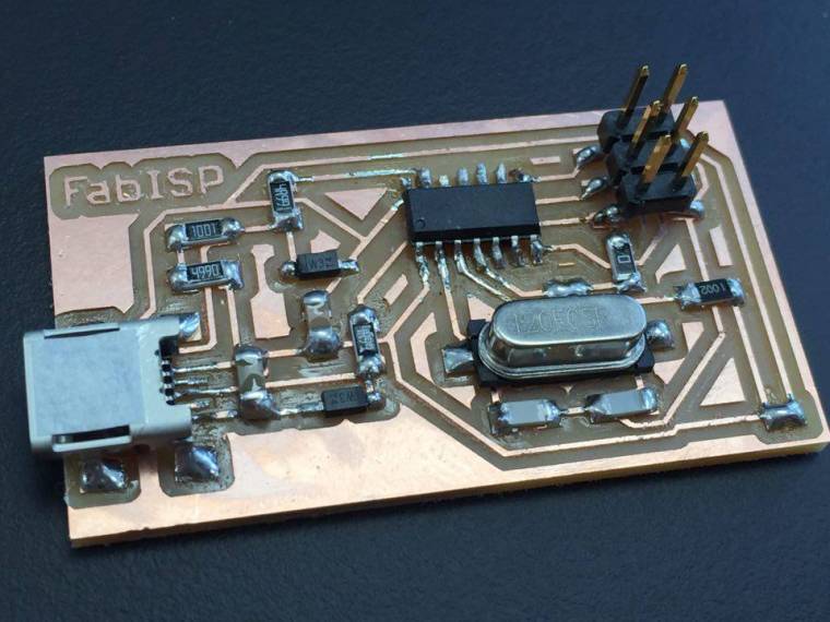
This week I was cutting out a circuit and soldering components on it.
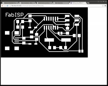
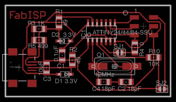
I went with David's design of the hello board. I downloaded the files and saved them in a folder on the desktop.
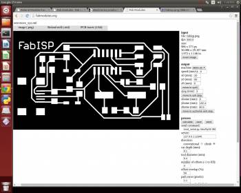
I went to Fabmodules.org and uploaded the the first png file. I chose the roland mill (.rml). Next I chose the end mill I was going to use which was 1/64. Then I selected the machine (MDX-20) and changed the send command to “S0” instead of “USB0”.
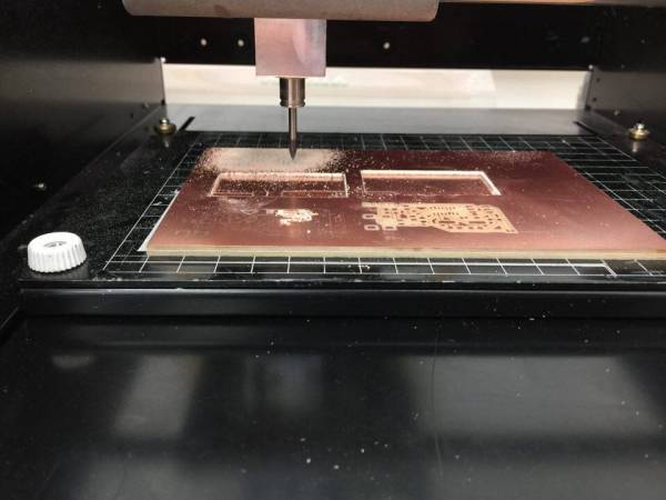
First step was to set the start point for the cut.
I opened a terminal and made it listen to a port, you can find the commands on the Wiki.
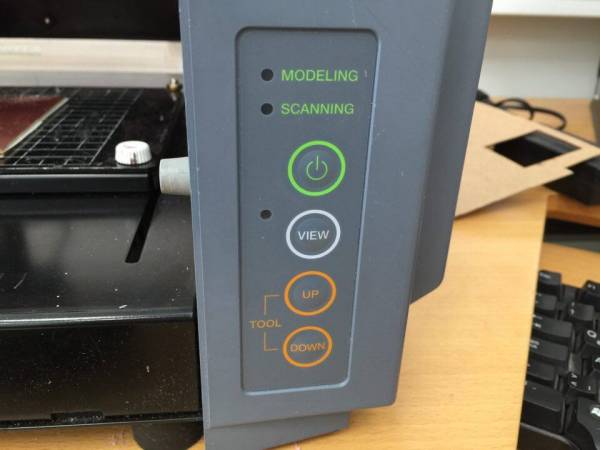
Next up I simply pressed the on button and then view.
I then navigated the mill to the desired start point.
For the X and Y axis I typed in the values in mm in the program. For the Z axis I had to use the up and down buttons. Lowering it down to a point where I could carefully lower the end mill so the point of it touched the board.
Friend of mine pointed out that I should set the cut depth to 0.2 instead of 0,1 (mm), he had been running some tests earlier.
I then let the program calculate a path and hit send.
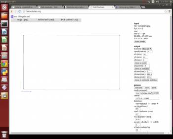
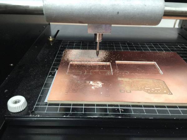
Now I need to load the machine with another end mill to do the cutout around the board. The process was the same but uploading the second png file and selecting 1/32 mill end. I loaded the 1/32 mill end and did the same process for the Z axis while I didn’t change the X and Y values.
I used the default settings, calculated the path and hit send.
Now I just cleaned the board and it was ready.