
ELECTRONICS DESIGN
This week is dedicated for electronics design. I use the following softwares for designing the boards.
KOKOPELLI
kokopelli is an open-source tool for computer-aided design and manufacturing (CAD/CAM).It uses Python as a hardware description language for solid models. A set of core libraries define common shapes and transforms, but users are free to extend their designs with their own definitions.
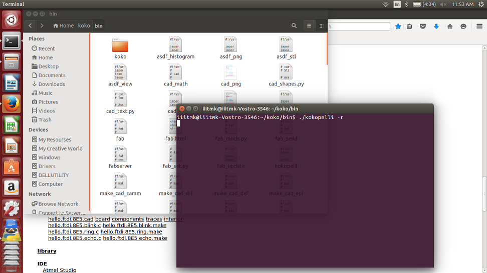
Franscisco introduced us Kokopelli. We started playing aroung it by downloading the FTDI hello world examples shown in the following screen.
We added a button and LED to the existing board and learned how to tinker with kokopelli
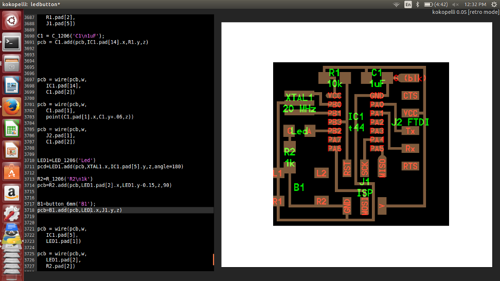
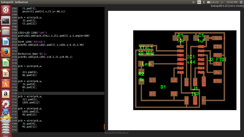
In kokopelli we never draw a circuit, instead we write codes for that as shown below. The graphical reasult is shown to the right.
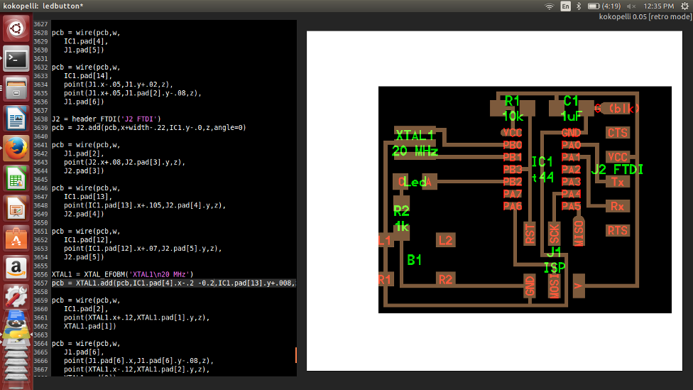
Once the initial starting trouble was overcome, playing around kokopeilli was fairly straight forward and easy to understand. We should understand how each component is added as classes and how to place them in the borad refereing to another component already exixting in the board.
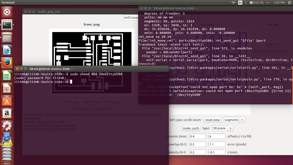
I completed the board with out much difficulty and it is ready to be exported for miling, while exporting we can mention the resolution of pixels. Initially I gave 10, but it was not sufficient and then I repeated the same with a resolution setting of 40.

Inorder to export the traces and board outline seperately, we have to comment or uncomment the desired output settings available in the initial part of the code as shown below.

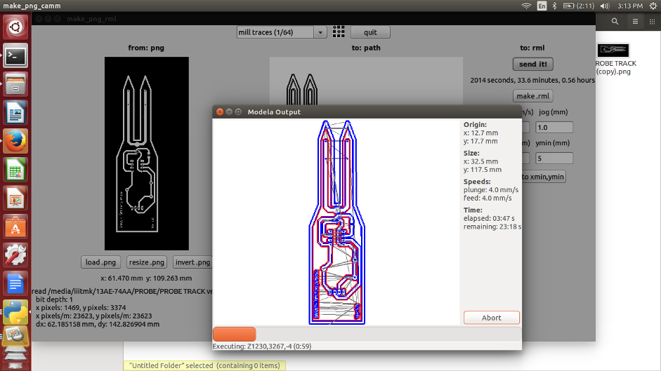
The image files are ready to be milled and the screen shots of the same are attached for reference. I am not givng a detailed description about how to mill PCBs as it is already explained in the Modella PCB Milling section.
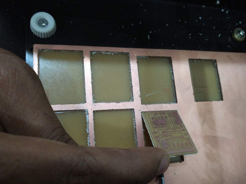
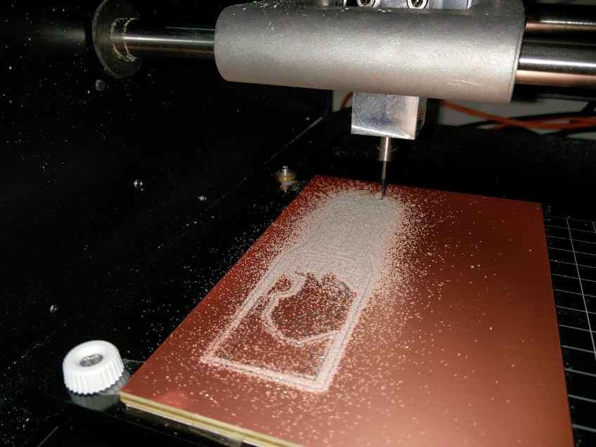
Milling the traces.

Cutting the board edges.

The completed PCB.
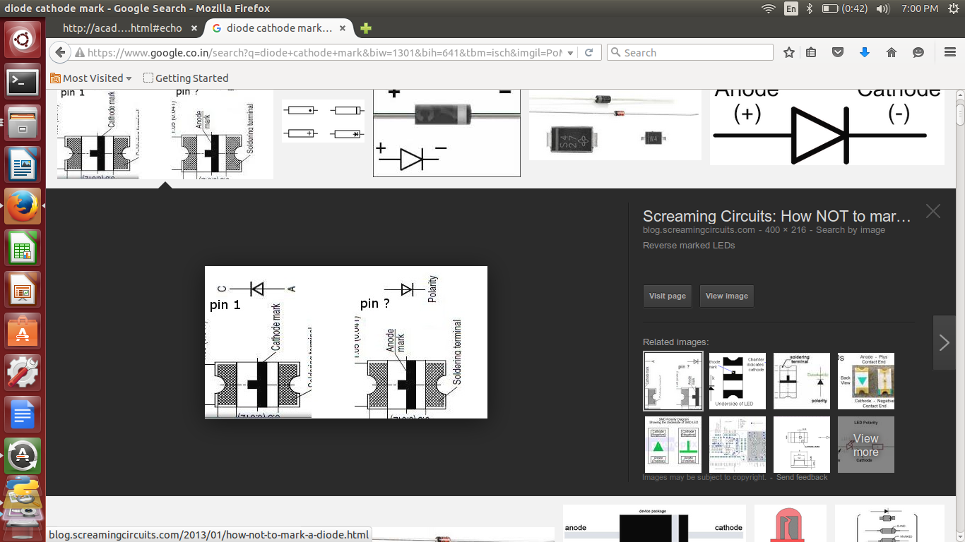
Now it is time to assemple the PCB, I had some confusion while trying to find the Anode and Cathode of the SMD LED, The following diagrams are for reference.
The completly assembled PCB.

The file used for the process can be downloaded from here
Eagle CAD
EAGLE stands for, Easily Applicable Graphical Layout Editor in English and, Einfach anzuwendender grafischer Layout-Editor in German. It is designed and developed by CadSoft Computer GmbH and is a flexible, expandable and scriptable, electronic design automation (EDA) application with schematic capture editor, printed circuit board (PCB) layout editor, auto-router and computer-aided manufacturing (CAM) and bill of materials (BOM) tools.
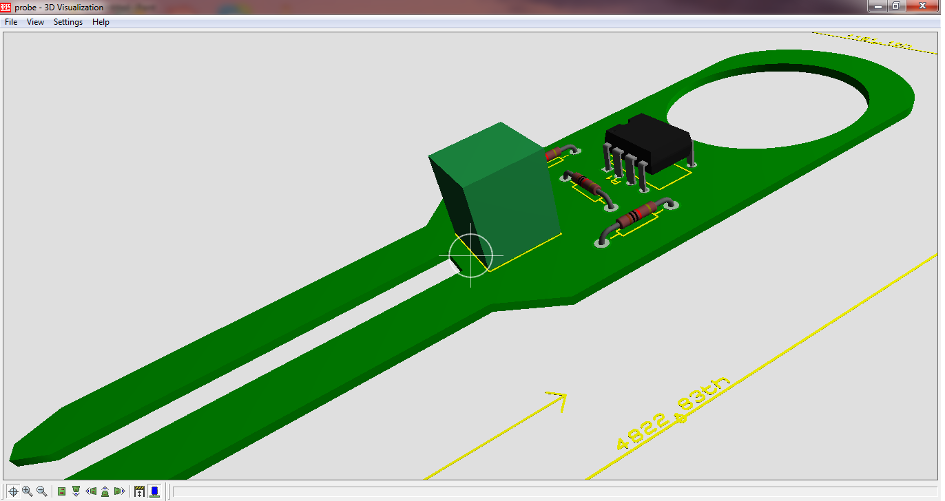
Here is some of my experiments with eagle in making a SMART PROBE..
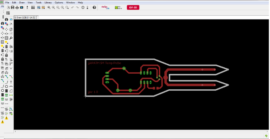

The file used for the process can be downloaded from here
PROTEUS - ARES
Proteus PCB design combines the schematic capture and ARES PCB layout programs to provide a powerful, integrated and easy to use suite of tools for professional PCB Design..
All Proteus PCB design products include an integrated shape based autorouter and a basic SPICE simulation capability as standard. More advanced routing modes are included in Proteus PCB Design Level 2 and higher while simulation capabilities can be enhanced by purchasing the Advanced Simulation option and/or micro-controller simulation capabilities.
Here is the schematic capture of the Hello world fab example.

Here is some of my experiments with Proteus in making a probe.
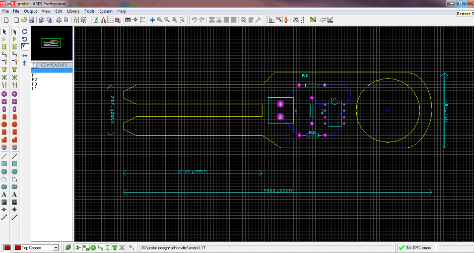
One of the attrctive features I found in proteus is its ability to give a 3D preview as well as the ability to export them as stl files.
The file used for the process can be downloaded from here