
Read a detailed datasheet of attiny microcotroller(MC) and elaborate learnings and doubts and things I like to know more about.
Learn different approaches to program attiny or avr's and program helloftdi borad(or any other board) we created in week 6 with an led using different approaches.
To get a basic overview of the process involved in programming avr I highly recommend go through
https://youtu.be/ERY7d7W-6nA
Which is an introduction to another really great source of knowldege about AVR programming which is a book by Make. Make: AVR Programming
Programming language
Hardware- Programmers.
These are just the programmers that we have access to but there are other also that can be used which are illustrated in the video as well as the book.
I will using the FabISP as the programmer to program the helloftdi board I cretaed in week 6 assignment.
For the below I have connected FABISP to the compute using mini USb cable and connected the hellofdti board to the FabISP using a 6 pin ribbon cable. The orientation have to in the right order only then the program can be uploaded. The MOSI pin has to be connected to MOSI and so on. If you are having trouble uploading you can try different orientation of the conector on the hellofdti board and check if that is working.
You will need"
Hello ftdi. Edited so that an led and switch is added.
6 pin Header cable(6 wire Ribbon cable).
FabISP
Arduino IDE 1.6.5 or higher with Atttity addon
Connect the FabISP to computer and connect the hello FTDI to the ISP using the 6pin header cable. Connecting header cable: When you look at the arrangement of the ATtiny44 and 6pin ISP jumper arrangement you will see that they are placed and oriented alike in hellofdti and the FabISP board. They remain the same in many of the circuits and it is a nice orientation to recognise the pins of the ISP so that it can plugged easily. You have connect the ribbon cable such that the notch in the ribbon cable face the same direction in both the boards(either towards the Attiny or away.). If we do this then MISO,MOSI etc of FabISP connect to the MISO,MOSI etc of the hello ftdi exactly.
Arduino IDE settings
In Tools go to and pick.
Board-> ATTiny
Processor-> ATtiny 44
Programmer-> usbtinyisp
Clock -> 20Mhz External
Port-> ttyUSB0(if multiple devices are shown you have to figure out which is the port FABISP is connected to)
After settings you should burn the bootloader into the board.
use Tools->Burn bootloader
The burn succeeded.
When you have a successful burn of bootloader you can start uploading the programs you wrote to the hello ftdi using the isp.
The bootloader is something like a BIOS of the MC that is written once into the MC and is a program in itself that takes input from the ISP pins and writes it to the flash memory in the chip.
Init and loop sections are common to any c prgramming related to AVRs.
Setup or init part of program- one time execution. It is used to setup input output pin or pwm etc.
Analog input- Use analog to digital converter to get meaningful data from an analog source.
Analog Output- PWM is used to output rather approximate analog output.
The setup program comes under
Every pin delivers- 5v max and 40mA current.
Input- reads 0 or 5v
Loop- statements under the loop are going to be executed in loop or a cycle as long as the MC is powered.
Pin number that arduino ide refers to is not same as attiny pin numbering so look at google for "arduino ide attiny pins". The following is the image I found.

In my hello fdti I have connected the LED to pin 8 and the button is connected to pin7.

Blink LED
We used an example program, blink. It is located under examples->basics menu. First we try to run the default program with only the pin numbers change to pin 8.
The following is the code.
Trigger through Button
Now we try to switch on LED with the push button Activate the internal pull up for stability using digitalWrite(); in the setup.
Internal Pulllup- If pull up is not activated then it will be susceptible to external electromagnetic noise. Essentially an open switch is connected to air and can be affected by electromagnetism of the air. If you have some potential and try to get your finger close to the circuit the switch condition will change. You might see it flickering or may be not, with conditions it changes. With internal pullup the pin get a high through internal circuit and only when the button is pressed will it be given a ground or 0V signal. In our case the push button is connected to gnd and so the logic should go like when the GND or LOW is detected in pin 7 the LED lights. And the normal state is the HIGH state.
We are supposed to lookup the pin definitions in the datasheet of Attiny44 but fortunately the kokopelli .cad file also had the required information. If this had caused problems I would check the datasheet.
Blink LED
Checking connections using Avrdude.
The boards have to be connected together for this to work. In Ubuntu open the terminal and enter the following
'sudo' might be required to give permission to write to USB serial ports.
-c option specifies the programmer.if type in just 'avrdude -c' avrdude will output a list of programmers in code the avrdude recognise. Fabisp is a usbtiny programmer.
-p option specifies the board to be programmed.
if you type 'avrdude -p' avrdude will output a list of codes for ICs the avrdude recognise. Attitny44 has the code t44.
This should give you an output like.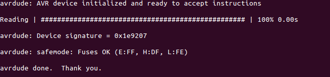
Errors.
'initialization failed,rc=-1' error means that there's an issue in the wiring, may be you need to flip the 6 pin connector and connect to isp.
If you run into error with device signature it means you might have used a wrong device code. Here I am using fabisp whose code is usbtiny and board is attiny44 for which the code is t44. If arduino is used as isp its code will be arduinoisp and for atmelice device the code is atmelice. These are the options available at our fablab.
If you find signature like 0x0000 or oxffff, it might due to loose contact in wires.
For 'Could not find USBtiny device' error type 'lsusb' to list all the usb devices. My computer lists fabisp as
Makefile I followed the steps for creating the makefile from the book 'Make: AVR Programming' pg 37. I downloaded zip file from the git repository https://github.com/hexagon5un/AVR-Programming. This is a repository that has sample codes and examples that the book uses. I created a folder and put my my c -code and the makefile in it and proceeded to modify the makefile.
In the makefile I made the following edits.
PRhelloftdiBlink is the name of the c file which has the blink code. I uncommented the option to specify target by name and commented the lines that take target as the name of the folder that it is under and assumes that there is a c file but that name inside it.
After the above edits I saved and closed the file. The file has to be called 'makefile'. The 'make' command recognises and executes a file named 'makefile'.
Upload program
To upload the program into the board, I opened the terminal in that folder and typed 'make flash' with 'sudo' permission.
The programed got flashed successfully. It did gave an error of rc-1 communication, but that is because I forgot to include 'sudo' before make flash.

Common Pitfall Even when the program flashed successfully I found that the blink was working. The error messages are really useful to isolate the Errors. I found that a ';'was a miss in one the lines due to which it failed to compile properly. After tidying the code the program worked just fine and the LED started blinking.
Download c file Download make file
Button Trigger
Program There are some macros(function as I understand) supported by the avr-gcc while allows the program to read easily. bit_is_clear(pinname,pin number) and bit_is_set(pinname,pin number) are one of them.
I tried this same code while commenting out the internal pullup code and when I uploaded it the LED remained ON no matter if the button was pushed or not. Actually the logic was supposed to be reversed, now the LED should have gone off when the button is activated. This is the reason why pullup logic is used.
Download c file
Download make file
I went through the tutorial in http://www.avrbeginners.net/ to get a basic overview on the programming avr's using assembly. Though a lot of it I wasn't able to completely understand like stack and setting origin and interupts or sequential execution and priority of interupts, I was able to get enough info to get started on. Things I focused on were, header content, main program, how to create a delay and compiling and program and running it.
The basic structure goes like this
Delay here is created from infinite loops which are designed to take a specific number of clock cycles of the MC or waste them. Its purely based on mathematics I generated my delay loops using http://www.bretmulvey.com/avrdelay.html
The generated delay loop code for 20MHZ crystal and 1 second was
To generate the hex file I used gavrasm. It accepts file with extension .asm and code is
On successful compilation it generates a .hex file that can be uploaded using avrdude. If not it shows Errors that you can debug and try again to compile.
To upload the program(assuming the fabisp is connected to computer and the helloftdi or any other board is connected in proper manner with the fabisp) I the command
While reading the datasheet what I found was it is not meant to be used a instruction manual, the user friendliness of it is nil. The examples are minimal and avoided too. But I think its something you master over a long period of time. The microcontroller can do many things and it can be elaborated in 1000 pages of book but the datasheet is the bible by whose rules things happen and if something happens different, its either a miracle or you fried the microcontroller.
I found it useful while trying to find out how to use ADC to read analog values.
What I found was that there are numerous terms the interpretation and meanings of which I get scared to comprehend. But once I went through is a couple of time I became used to it and I am now in a position to tell if the microcontroller can do something regarding analog reading or not.
I found out that the just like any memory device , the microcontrollers can also face data corruption and apparently there are ways you can make it less likely.
Question:
“The ATtiny24/44/84 AVR is supported with a full suite of program and system development tools
including: C Compilers, Macro Assemblers, Program Debugger/Simulators and Evaluation kits.” - Datasheet pg 5
I dont understand what macro assemblers are, and where to find simulators and what exactly are evaluation kits.