
I come from a mechanical background and not new to the CAD and the tools thats are used.I am familiar with Solidworks and have used it on many projects. I tried flood but found it hard to use because of the lack of help or tutorials.
I started playing around with fusion as it came highly recommended from Neil. It offers a free license for startups and educational purposes, which is a boon I think. It is very similar to
Solidworks in how it deals with solid modeling but has a lot of added features. Interesting features of fusion 360: The CAD, Sculpting, CAM, Rendering, Animation and Simulation all in a package. It also cloud based and stores versions of your designs for you to access. With all these in one package I can see fusion 360 going to great heights.
Solidworks offers one of the most professional solutions for overall product design. You can addon packages that for various purposes suited for your product design need, for example for plastic design, sheet metal design, flow simulations etc. I am used to the solidworks workflow the most. But it is a commercial product and if I only care about the 3D design it might not be the best option. It might not be the most beginner friendly, but once a person goes through some of the tutorials it becomes very intuitive to use with minimal hitches.
Here I have used Solidworks to design some components and shown its parametric and functional features.
Rhino gives the most control regarding elementary features of a solid model, Its edges and surfaces. I even used rhino to edit meshes but to lesser degree of success in what I wanted to achieve. But for solid modeling rhino proves to be very versatile and feature rich. Only problem is that rhino costs much even though not as much as the god of all Solidworks.
Here you can find my works on rhino.
Onshape is a fantastic cloud based online tool, offering solidworks like workflow and features without any installation on local system. Onshape claims to work even on phone. I found it extremely useful when I didnt want to switch to windows just for design purpose. Even though there are some lags while designing since its an online tool and I do not know how well it would perform when the jobs gets really complex and big. You can have 10 models that are private and if you want more models to be private you need to pay for pro features. This does a great job if paramateric and functional 3D design is what you are looking for an you need a non windows also alternative. The project version feature is also great. In this it is similar to autodesk fusion 360. Fusion is extremely feature rich but onshape work cross platform.
Here is my work on Onshape.
After evaluating many 3d design software I decided to try out Fusion 360 for 3d design. I love to design in Onshape and Rhino too.
You can get a basic overview of the things your can do with fusion in the Autodesk videos:
Marketing overview : https://www.youtube.com/watch?v=tpuVfUrPb4U
Overview and working: https://www.youtube.com/watch?v=gu7Nm0ygaow .
Creating the possible final project.
We can start using the primitives directly build on them or modifying them. My project contains cylindrical bodied links or arms that are constrained at the ends with revolute/hinge joint. The final rendered project looks like:
In fusion 360 we first create bodies that have the form we want. The final form can comprises of primitives, that are modified, or objects that are created out of sketches. The form generated is used to create components(right click on body in the project tool menu located in the left of the screen and select a body you created and choose ‘create components from bodies’). The components can be assembled and constrained at joints with respect to each other and final motion is created.
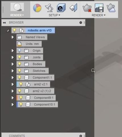
To get a better idea about how the project tree is organised you can watch: Working with Components : https://www.youtube.com/watch?v=6J_mCpV7_2w .
Primitives are well defined forms such as cuboid, sphere, toroid etc that can be used to begin a form or design.

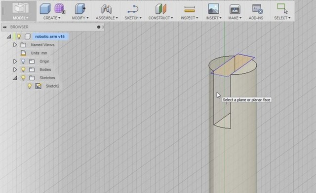
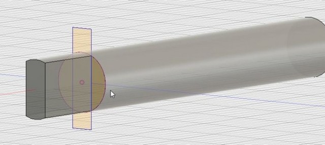
Extrude is well known feature of a 3d cad modelling software. Here it is known as press pull (shortcut- q). You can either use it to cut through a material or build on it. Fusion allows you to extrude a plane face directly(in case you want to extended the length of that face) or a sketch that is created on a planar face. To enter the sketch mode click on the sketch menu option. A sketch is drawn on a planar face. You will be assited visually to choose a face by highlights and colors. Choose the plane you want to start your sketch on after a sketch is finished you can choose to quit sketching mode. If you are creating a sketch with reference to features of an existing form you have to use construct featres such as points and planes for that feature to be accesable to you.

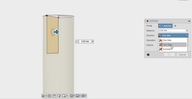
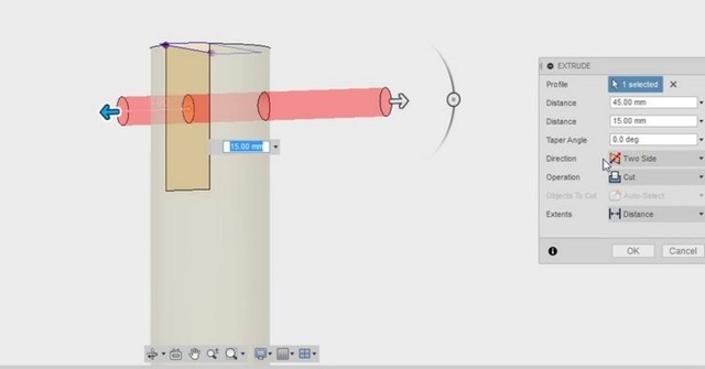
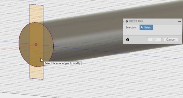
Now use the presspull option under the modify menu or press the shrtcut q. The selector is intelligent enough to understand and segregate different segment of the sketch you created based on feature of the underlying plane. For example in the above figure you see the rectangle is cut into three segments by the underlying circular face of the cylinder. Using this option you have freedom to create an approximate sketch and you need not worry about re creating the edges of the underlying face exactly. You can give a value to how far the extrusion need to be out of the face (positive values) or how deep it should cut(negative value).
There are also option for two way or symmetric cutting or extruding.
 .
Here is an example where press pull(q) is used to add a feature instead of cutting.
 .
.
 .
.
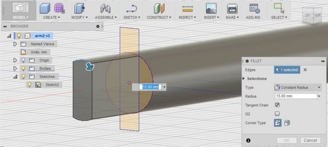
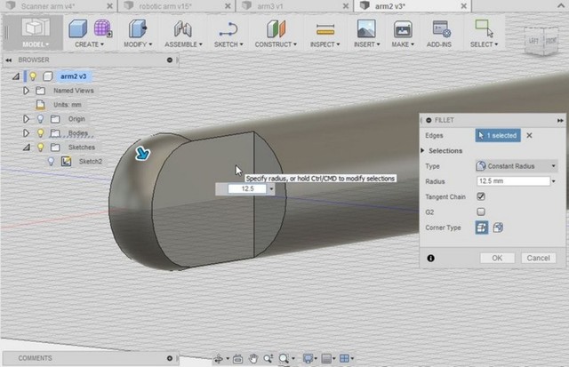
Fillet is used to create round corners from a sharp edge. You can specify the radius of the fillet. Fillet is found under the ‘modify’ menu.
 .
.
 .
.
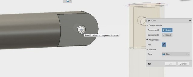
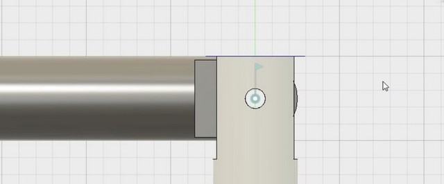
My design uses revolute kind of Joints, which allows in plane rotation of the links. Joints define the relative motions and offsets of two components relative to the joint center. We choose joint centers for each of the components. These components become coincident at the joint centers chosen and the joint type and the ranges for relative translational and rotational degree of freedom can also be set. Joint(j) option is found under the assembly menu. There are different constraints available to choose, such as ball joint, revolute, rigid etc. In the pictures below we can see how the revolute joints are created between two links with hole for a pin to pass through. In real world the pin would act like a constraint in cad modeling the same is replicated.
 .
.
 .
.
 .
.
For more detailed demo for alligning parts and making joints in between components, you can watch. Moving and aligning : https://www.youtube.com/watch?v=t81V6zNRKFQ .
Joints and motion : https://www.youtube.com/watch?v=nngmNos6VI4 .
Fusion 360 stores the design process as an event in a timeline. You can go to a point where you want to edit that feature and it will reflect in the final model as well
.
Evaluation and my impressions on 2D design softwares
I like draftsight for 2D applications which doesn’t require raster graphics. For those involing raster graphics I use Inkscape, gimp, pixlr editor online.
Draftsight
Draftsight from Dassault systems is an autocad clone and pretty much does the job for any2D engineering drawings. I know the some shortcuts to help me during a drawing and these tools are helpful for engineering drawing purpose.
Inkscape
Inkscape has a good toolset but I didn’t find it very intuitive to use and it is helpful if you go through a tutorial. It might take you long time to fully use inkscape to its maximum potential.
Gimp
Gimp is a very powerful 2D and raster design software. But it has certain workflow which needs getting used to and is most useful for people who understand some advanced topics in graphic design. I use it only for certain jobs like inverting color.
Pixlr editor
Its an online tool and one of my favorite graphics editing tool. More on its use in my other pages Vinyl cutting
I attempted to create a logo to experiment with the 2D vector and raster tools.Its one of my scribbles which I used to do in school. When bored in class. I needed to use spline feature for freeform drawings. Needed options to fill color. I ended up using combination of draftsight, gimp and inkscape to create what I had intended to create.

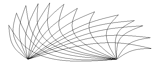
I attempted to create the form using inkscape but found its spline feature challenging to master. I switched back to my favorite tool draftsight and was quickly able to draw up the form. Draftsight is a most straight edged tool used to created line vector drawings with engineering drawing as focus, but like in this situation can also act like a powerful creation tool. The final design looked as shown. The splines in Draftsight were much easier to use than that in inkscape.

Now I needed to color the alternate checks. This option was not available in draftsight and I had to find a software with raster handling functions. I exported the drawing in png,jpg, eps, and svg formats. The best result was from the eps and svg format. These are the formats that preserve the vector information hence work well in preserving form in terms of vector. Png and jpg can only store the curves in a roughly approximated pixelated form.
Pixelated png
Clear lined svg

Again I tried using inkscape but found that a simple bucket fill function also proved to be challenging. It was somehow just creating just an offset line instead of filling the the entire check. Later I found a solution for this.
I moved to gimp to fill the checks now. The bucket fill feature here worked like a hammer on the nail doing its job quickly. But it had a problem because it didnt fully fill the check. Gimp sees the vector line as a color gradient instead of a sharp line. Hence there is always a tiny gap left here or there which are left not filled. If you zoom in close enough you will be able to see some patches that are not colored or colored different.
![]()
I switched back to inkscape to try to fix the issue as I guessed it might have to do with ‘fill and stroke’ option. I found that it is because I had enabled stroke painting in the ‘fill and stroke’.The fill and stroke dialog is activated by option found under ‘object’ menu.
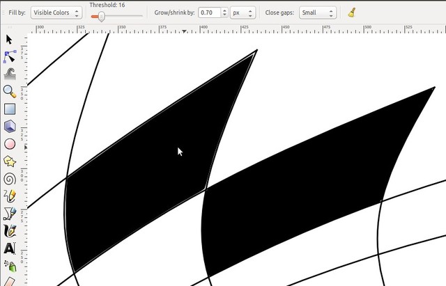
Now I was abe to fill in the checks as I want. Usually it tries to leave a thin gap between the fill and the boundary. This can be overcome by using grow/shrink options of the bucket fill feature. The picture here shows a flush fill and a fill with a little gap.
Download xcf
Download dxf
Download png
Download jpg
Download svg
Download eps
Download final png
Download final jpg