
Tools used
I found pixlr to be most useful. I aplied the following adjustment and filters in the same order.
Adjustment->
Threshhold-adjust till you satisfy in order to get a .
Filter->
Denoise - in order to reduce noisy points.
Haftone-to fill gaps and give some volume to the picture. To your satisfaction.
Wand tool- In order to select the part you like.
Brush tool or eraser- In order to give finishing touches and remove the pathces which wand tool couldn't differentiate and select.
Gaussian Blur- In order to smoothen edges.
Other features that I liked are and may be useful are- pastel,pixelate and art poster(filter) and posterize and levels(adjustment).
Here's a gif to show the progress of the the picture creation roughly.
The gif was created from the website http://gifmaker.me/
in the zip file you'll find the pictures I use to create the gif.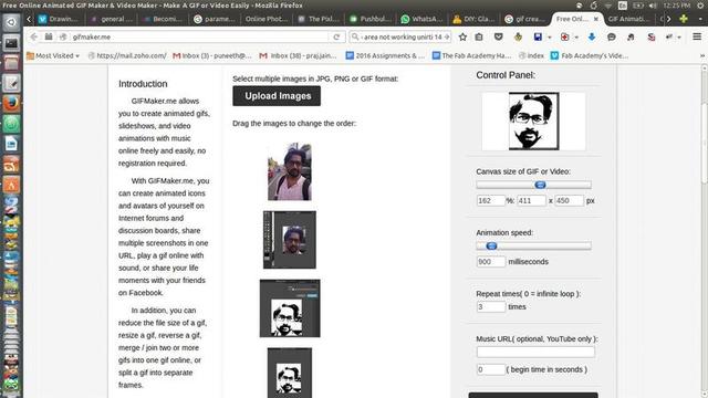 .
.
Note: I used a slightly different setings and process than what I used for documentation so the picture used for cutting is different.
The following steps are involved in setting up Roland Vinyl cutter. I went through the instructions documented by me during my pre-academy workshop at.
http://puneethrj.github.io/w2d1.html
The settings for cutting are shown in the following figure.
I transfered the vinyl cuyting on a masking tape.
The cutting on vinyl.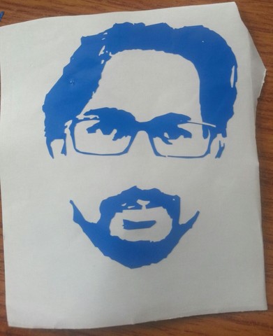
Tranfered to masking tape.

I transfer to my laptop.
As you can see the blue on black background didn't work that well. I had the negative also rearranged on a different surface just as experiment so I transfered that again from that surface to masking tape to transfer it to the back of my laptop.

I didnt get that precise a positioning since it was arranged by hands.
Initial thoughts
-3D representation of math functions-Represent a mathematical pattern or equation in terms of a press-fitted model. Like fractals. I wanted to find out if I incorporate a random number geneartor function(which is also a math equation) form a pattern in when visualised in 3D.
-Slicing algo-Attempt to make a script in antimony that does a job like autodesk make- split the 3d model in to 2d pressfit of sliced model.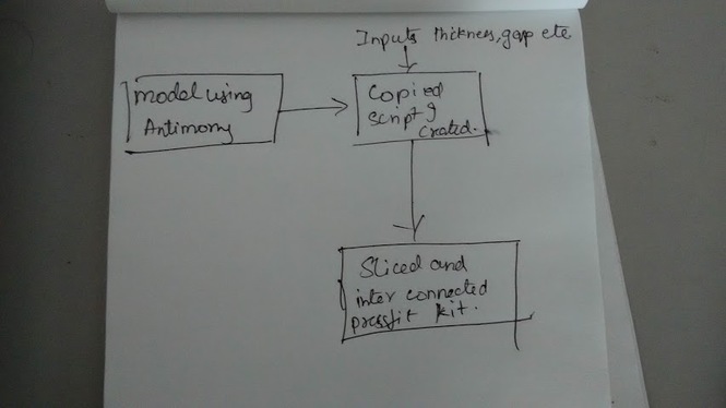 .
.
I decided to go ahead with slicing algo but ran straight into a problem. I opened the script of the xy slicing and found that some expressions are not understandable. This is the code in slice xy block. * import fab from fab.types import Shape
title('Slice (XY)')
def slice_xy(shape,z): return Shape(('mXYf%g' % z) + shape.math, shape.bounds.xmin,shape.bounds.ymin, shape.bounds.xmax,shape.bounds.ymax)
input('shape',fab.types.Shape) input('z',float)
output('slice',slice_xy(shape,z))*
Immediately I started to wish if I antimony had some debugging tools, I wanted to watch this expression 'mXY%g' in order to find out what does it out put. I found no option for it. I thought may a fullscale debugging tools wont be practical but at least an export to text option should have been there so that we can make some dedctions from the text that are output.
According to Matt Keeter's writeup on 2015 version of antimony http://www.mattkeeter.com/projects/antimony/3/ under the 'As an aside' heading he reveals that these are a way to express an equation in a code of a sort that are easy to parse but hard to understand. One would have make a deduction on their own or go through his thesis on how the representation is derived and how to get back a meaningful expression out of it.
As if this problem was not daunting enough I ran into another problem. I saved the project and closed it to research more the next day. I opened it the next day to find that the option to edit the script and function blocks was also not showing up. Here is a screenshot of the after and before saving scenarios and behavior of the function blocks.
Before save.
After save and open.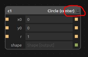
Seeing how complex it can ge and how long it can take to fully use antimony for my purpose I decided to pivot and try a different concept. I went through a couple of previous year pages and their assignments on the topic which inspired me to either try to convert my preacademy project(http://puneethrj.github.io/w5.html) into a pressfit construction kit or the proposed model in week 2(http://archive.fabacademy.org/archives/2016/fablabtrivandrum/students/369/w2/Assignment2_Computer_Aided_Design.html) for CAD as a pressfit construction kit, or do a laptop stand.
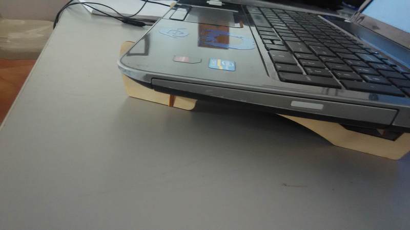
Laptoptop stand seemed the easiest and a good starting point on which I can build up.
I can do some really good designs or try out a concept where the mouse movement induces a motion in a fan to ventilate the laptop or from motions of hand while typing, or dynamically shapeshifting or moving stand.
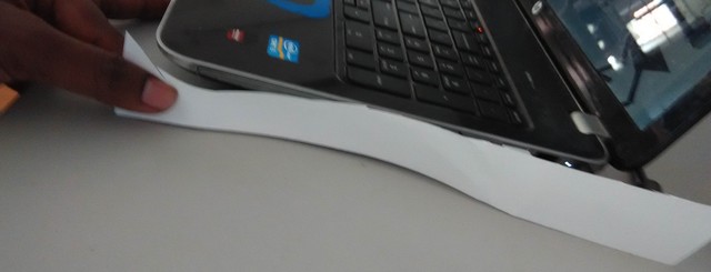
I made rough Sketch and a rough form cut in the paper so that I can actually it compare it to the laptop and check if it looks fine.
Sketch.
Rough paper cutting.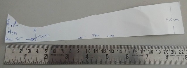
Compare


created components twice from the same body of the above.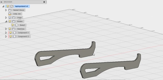
Created a rigid type joint between them with offset of 250mm.
Created a primitive cuboid form which with length 300, width 15 and height 4mm which will act as a cross bar to provide rigidity and pressfit into the side frames. I'll need two of these.
I created required joints to possition the bar but not fully.
The sideframes were positioned 250mm appart and rigid joint was applied.
One of the bars was alligned properly, pependicular to the sideframes and symmetrically but I wasnt able to figure out a way to position them precisely from the radius tipped end of the side frame.
Opened the dxf in Solidworks and imported as 2d sketch.
Problem: while trying to open the dxf it gave me an error that it has an incomplete dxf.
Solution:
You can open the dxf in draftsight again and save it in a lower version of dxf, I saved it as R14 ascii dxf. It opens fine in solidworks after that.
I did a standard extrude ad created another cuboidal feature as a cross beam.
Created the side frame structure extruding dxf drawing.
Created cross bar of approximate size. Later I sixed it to 300x15 since this I found in assembly was a workable size for the cross bar.
I created new assembly and added the above components. Two copies of the side frame and two of the cuboidal side bars.
Optional-While positioning the cross beams wrt to the sideframes you can either mention a calculated offset value or use advanced width mating that will automatically allign the cross bar symmetrically wrt the side frames.
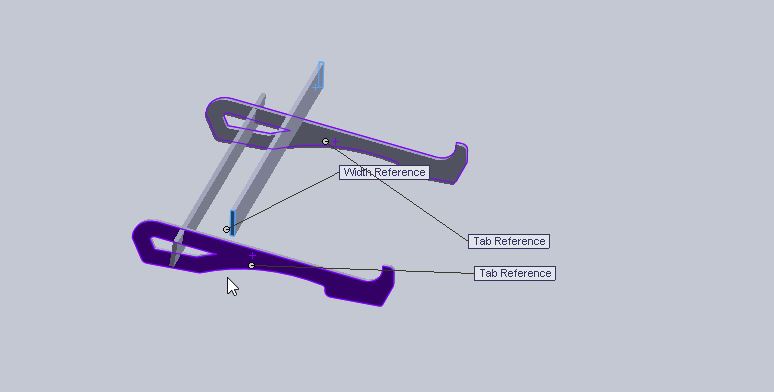
Advanced mate. If you want to assemble a feature symmetrically between two faces r edges, You select mate and select adavanced under the mate tab, Choose width type of mate. it Gives you two options, one is width selection the other is tab selection. For width selection choose the two two opposing faces that are perpendicular to the side frames like shown in the figure. The resulting mate will position the cross bar alligned symmetricaly wrt to the side frames.
Other surface were mated easily using coincident method to achieve the final effect as shown in fig.
Edit the part in assembly to make slots and interlocking with each other. Editing feature in place is a great help since you will be able to place features according. Right-click on component you want to edit choose 'edit part'.
Choose a possible plane to extrude cut the slot and make a sketch as shown in the following figures.
In general I found the mating features of assembly in solidworks way more user friendly that fusion 360.
Edit part -> side frame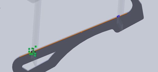
The change propagates to the clone.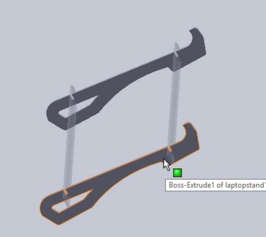
Edit part -> cross bar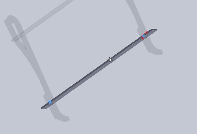
Propagating change.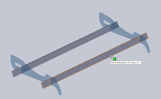
Export final dxf.
Once the slots are created right-click on the component and choose open part icon(open file icon). This takes you to a part window where the changes made in the assembly modeling space too. right on the side face of the side frame and choose 'export to dwg/dxf', go through the options, default should be ok, give a name and finalise export.
Device: trotec speedy100 Material: Corrugated Cardboard Power: 80 Velocity: 3
Problem: laser cut segment by segment- When you export dxf from solidworks directly or other 3d modeling software the drawing is entities are exported in multiple entities and not as a single loop. Its an open polyline or segments form.
Solution: Use Draftsight- mend it- Use PE command or PEDIT for polyline edit->Select multiple-> if asked to convert features to polyline select yes-> select join->select all the features you want to join in the model sapce-> return/enter.Sometime this works and sometime if it doesnt work you have to go deeper and check if there are any overlapping lines or intersecting features or something else wrong. Sometime you need to create the segment again or try joining segment by segment instead of selecting all at one time.
The cardboard prototype came out ok, they didnt tightly fit enough, form was captured well.The length between the frames need to be increased. Before I started using the plywood I decide to make a pressfit comb to check out different clearance settings for a good fit.

To create a pressfit clearance checking comb.
Creating an intelligent sketch that changes according to the thickness given. Sample pressfit comb.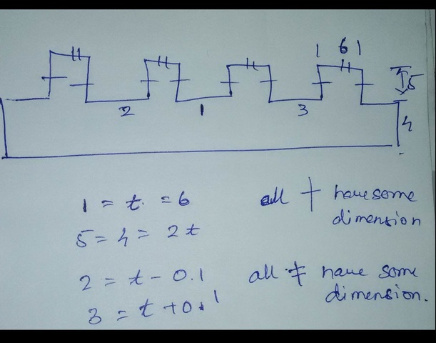
The pressfit comb is such that the comb thickness remain the same as thickness of the object we are trying to create the pressfit clearance comb for. It will have slots with thickness with clearances ranging from -0.3mm to +0.3mm in increments of 0.1mm. This will mean that it will create 7 slots ranging from thickness-0.3 in the left to thickness+0.3.
Device: trotec speedy100
Material: Craft plywood 3mm
Power: 90
Velocity: 1.5
Auto regenerating sketch.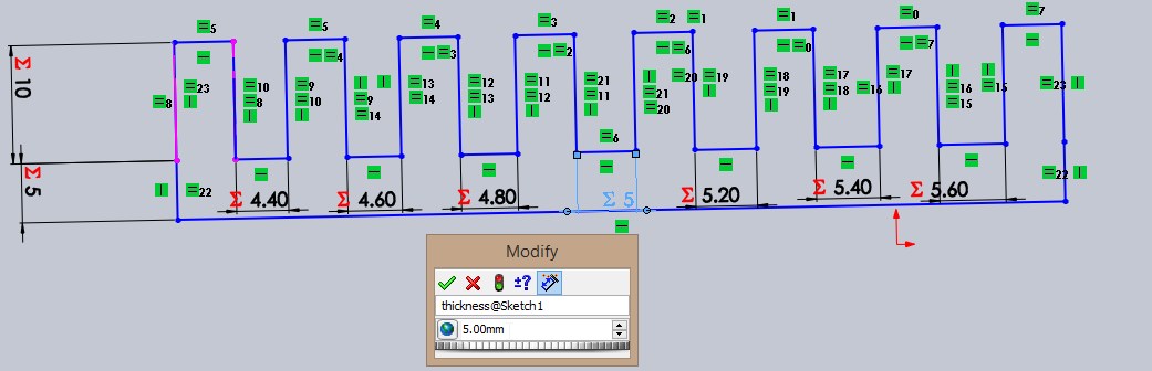
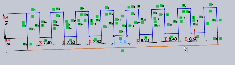
3mm slot was loose fitting and 2.8 slot was too tight when sliding a the ply through it. by interpolating 2.9 should fit good and give a tight fit I need but shoudnt be able to crack the ply.
My original 3D model was for cardboard of thickness 4mm but now I needed to create the model 3mm in thickness. It doesnt take much editing in solidworks to get what I want. I changes the extrude thickness to 3mm and changed the slot thickness to 3mmx3mm. But since I need slot thickness of 2.9 mm and it doesnt make sense to create a slot of 2.9 mm for material thickness of 3mm in solidworks(will cause mating errors due to inerference etc) I could either I can edit the whole assembly again for thickness of 2.9 or edit the dxf file to make the changes. If my design were complex it would make sense to make edits in solidworks and export the dxf again but there are only two parts here that are duplicated so I'm going to make change in the dxf using draftsight and make the slot width as 2.9 keeping the rest same.
