https://github.com/kevinphys/da_lamp
Currently I have made a hardware system and a quite robust structure. I could simply send commands by Android phone and the torque of servo seem perfect to move.
On my to-do list, I would say, at least, on Android phone should have build-in OpenCV system and could track simple shapes in the first stage. I am going to add computer version with Machine Learning system to recognise items on my desk later on. The best part is that I also have chance to play with Reinforcement Learning on the Kinematics of the lamp which means it could learn how to move by itself.
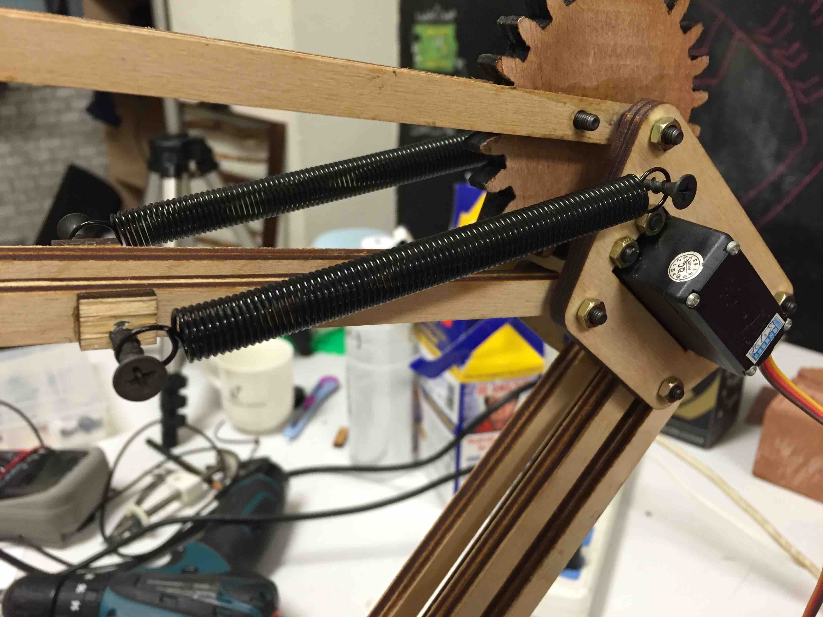
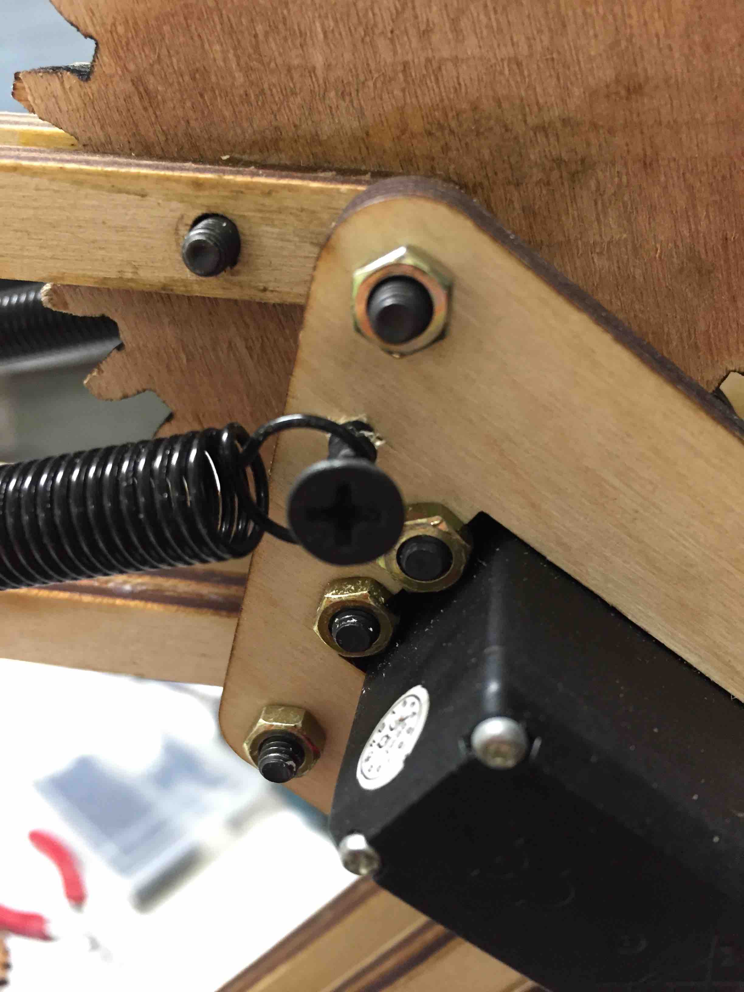
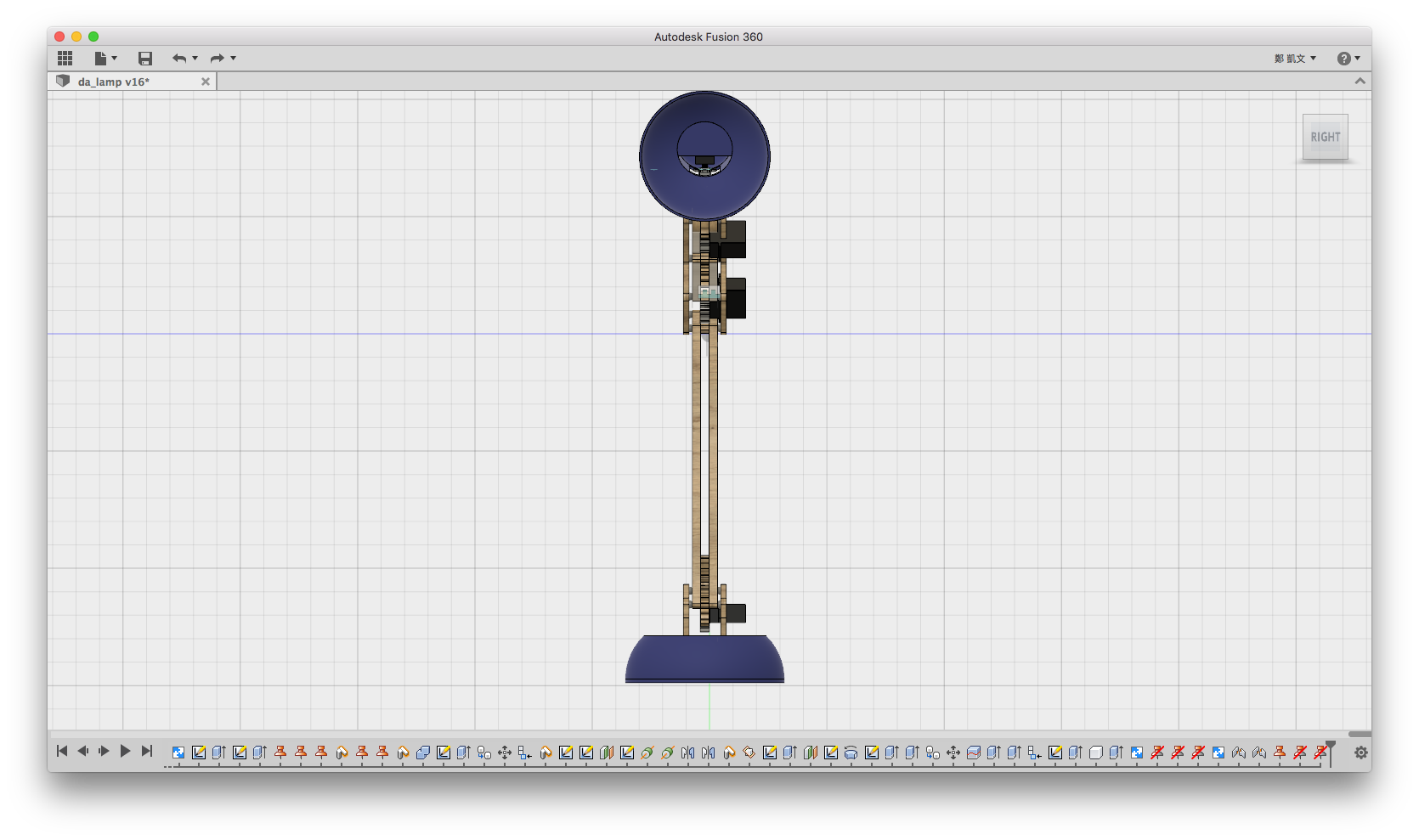
I just took springs from my old tertial lamp to DA Lamp. Before screwing them to the frame, I added some pieces of wood and redesign base frame.


I was looking for the bug which made the lamp so weird with oscillator.

Many thanks to Leon Chao in Fablab Taipei, he told me what I did wrong in my code. I did not use onReceive event for I2C slaves so that the nodes cannot response perfectly. Furthermore, I assigned 16-bits "int" but not unsigned 8-bits "uint8_t" and that could have made me send uncompleted bytes.
All bugs fixed in this commit.
First I tested sample code usb-serial-for-android by mik3y, and connected the USB OTG cable to my ASUS Zenfone 4 and Arduino UNO.

The result showed me that the communication between Andorid and Arduino did work and then I could just simply make my Android phone be the master. Following another tutorial could send commands through serial only with my phone but not computer.
The next step is that phone with OpenCV should play with all calculation and do the physical track.
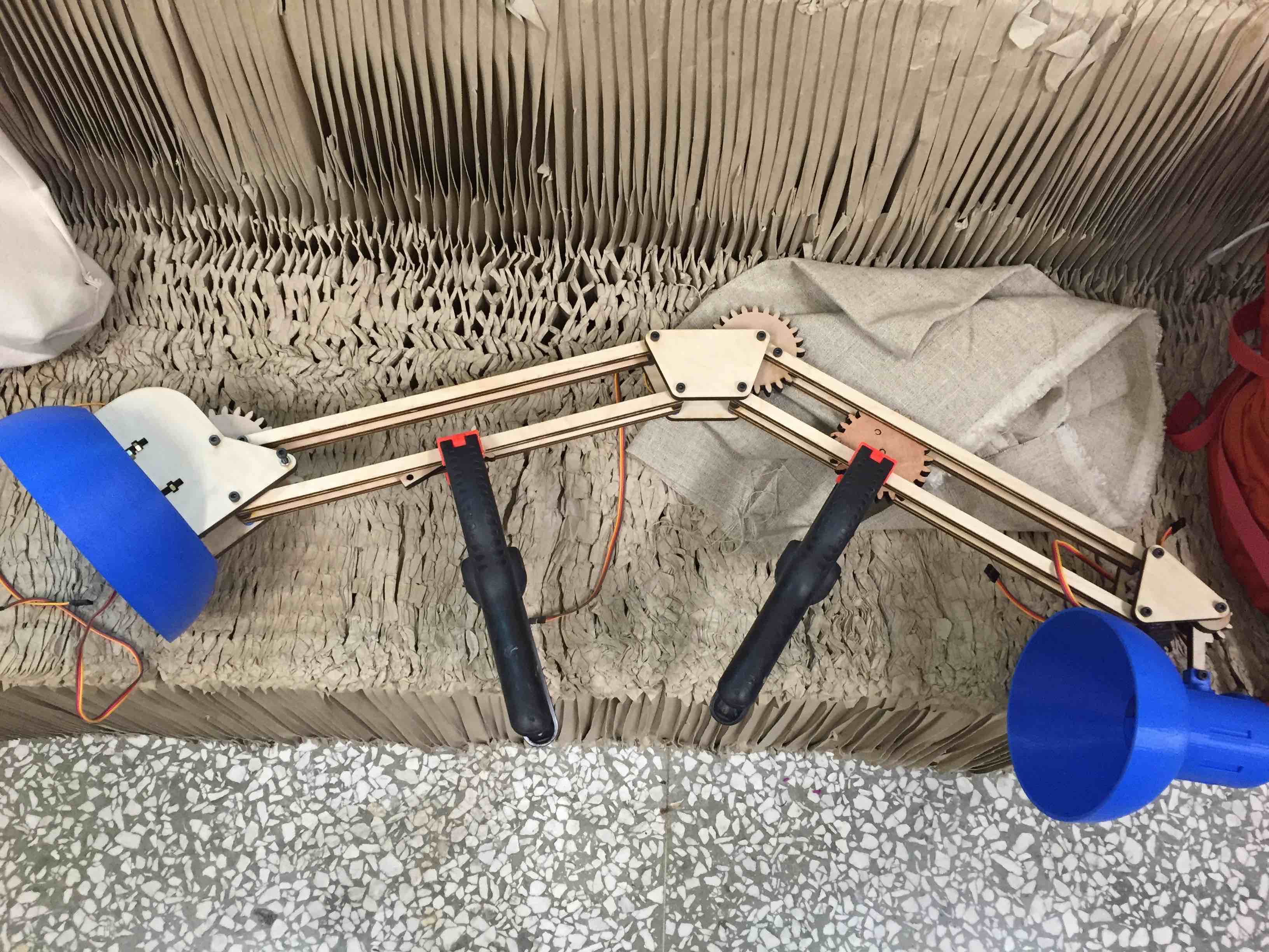
In week15, I've set a system which can send commands from computer to servo module nodes to generate PWM signal over I2C so that I have to use the system to make sure that every joints work profect.

In the video below, I was sending commands from computer to Arduino/Satshakit over serial. For example
1,90 which means (# of servo, degrees). Then Arduino/Satshakit would send angle degrees in unsigned 8-bit integer to nodes address directly over I2C. After that, the nodes would generate PWM signal in hardware mode.
In the video above, it shows that head and neck joints moved well but the servo worked too awful. Besides elbow and shoulder servos hardly turned to right angles.
There were couple issues in the test:
Springs to hold
It seemed having large torque which could make servos hard to work. Classic terital lamps all have springs to be stable, especially for elbow and shoulder.
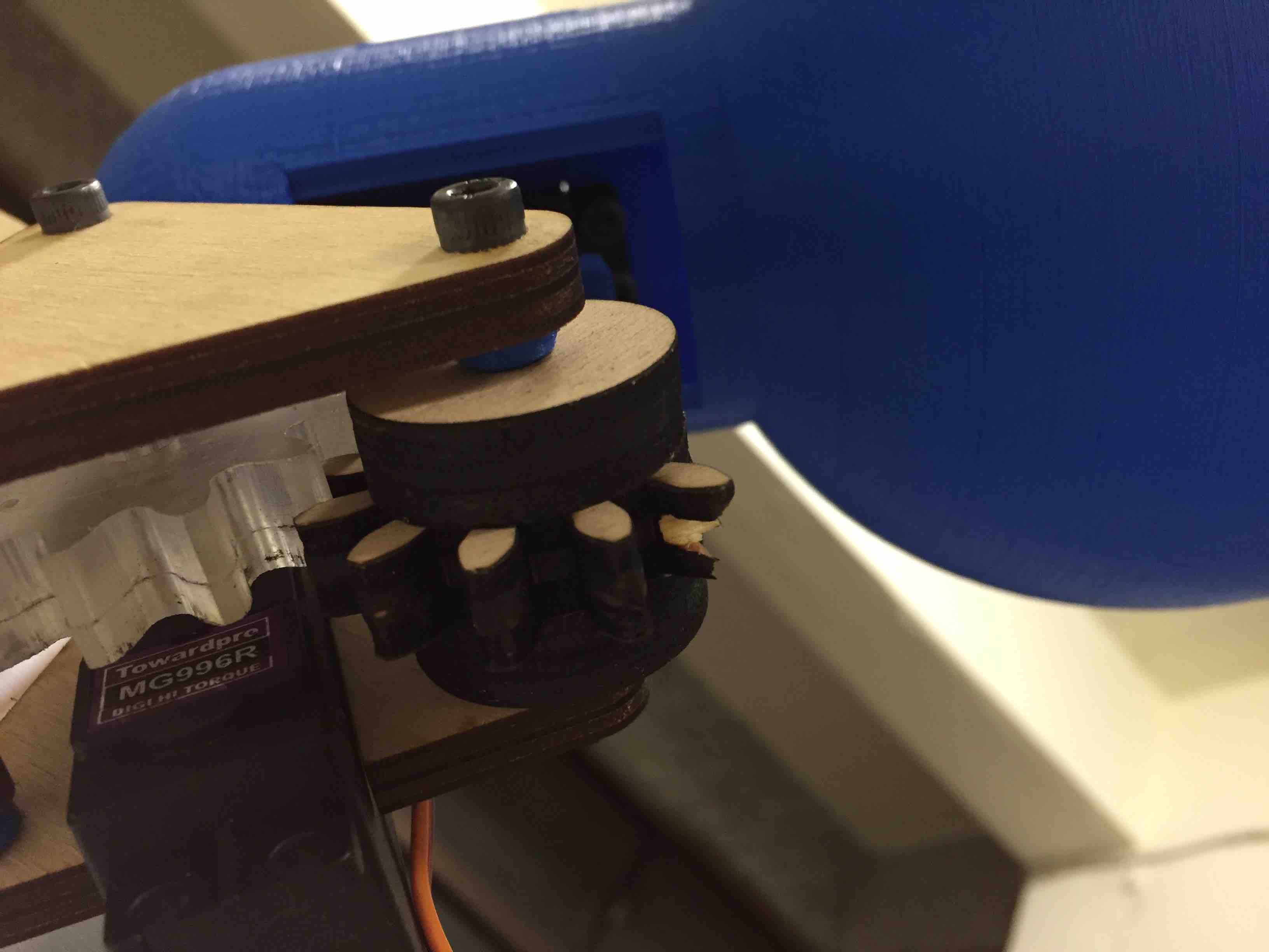
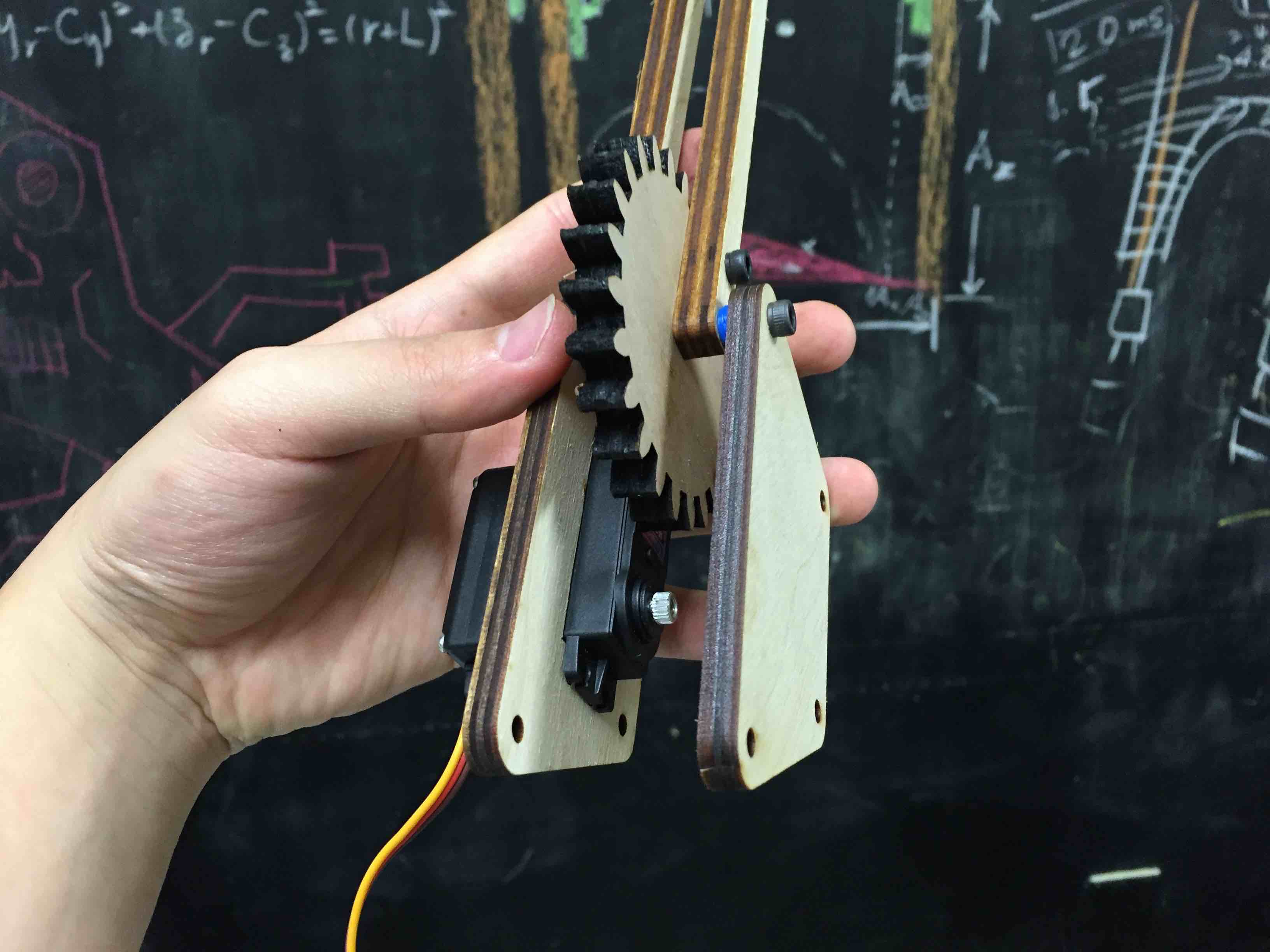
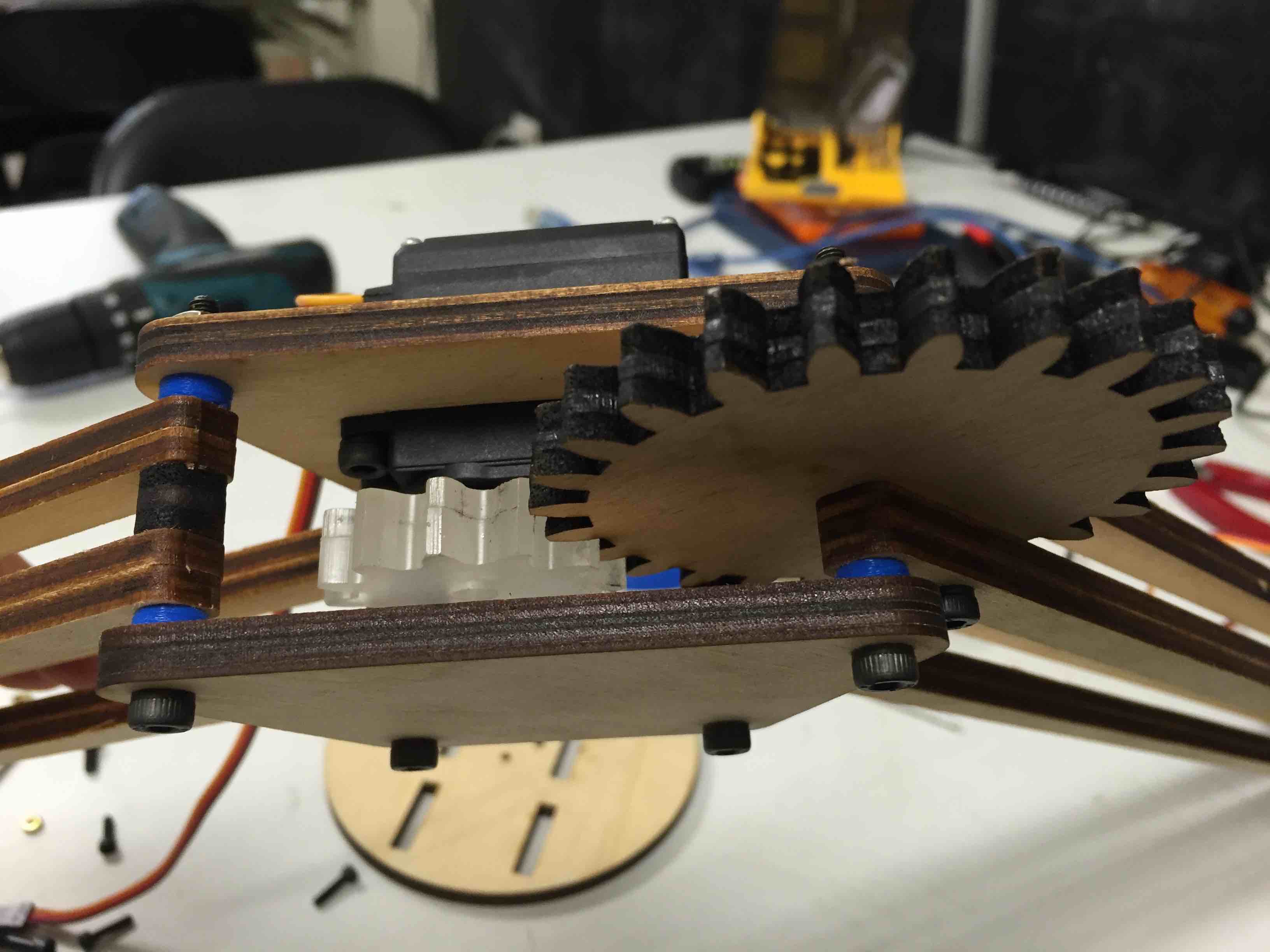
Redesign and repair neck gear
It was broken because of burnt weaken cross section of plywood. Also I have to increase the number of gear teeth.
Check hardware PWM signal
It might be something wrong with my codes on Arduino and nodes so I am going to check with oscilloscope.
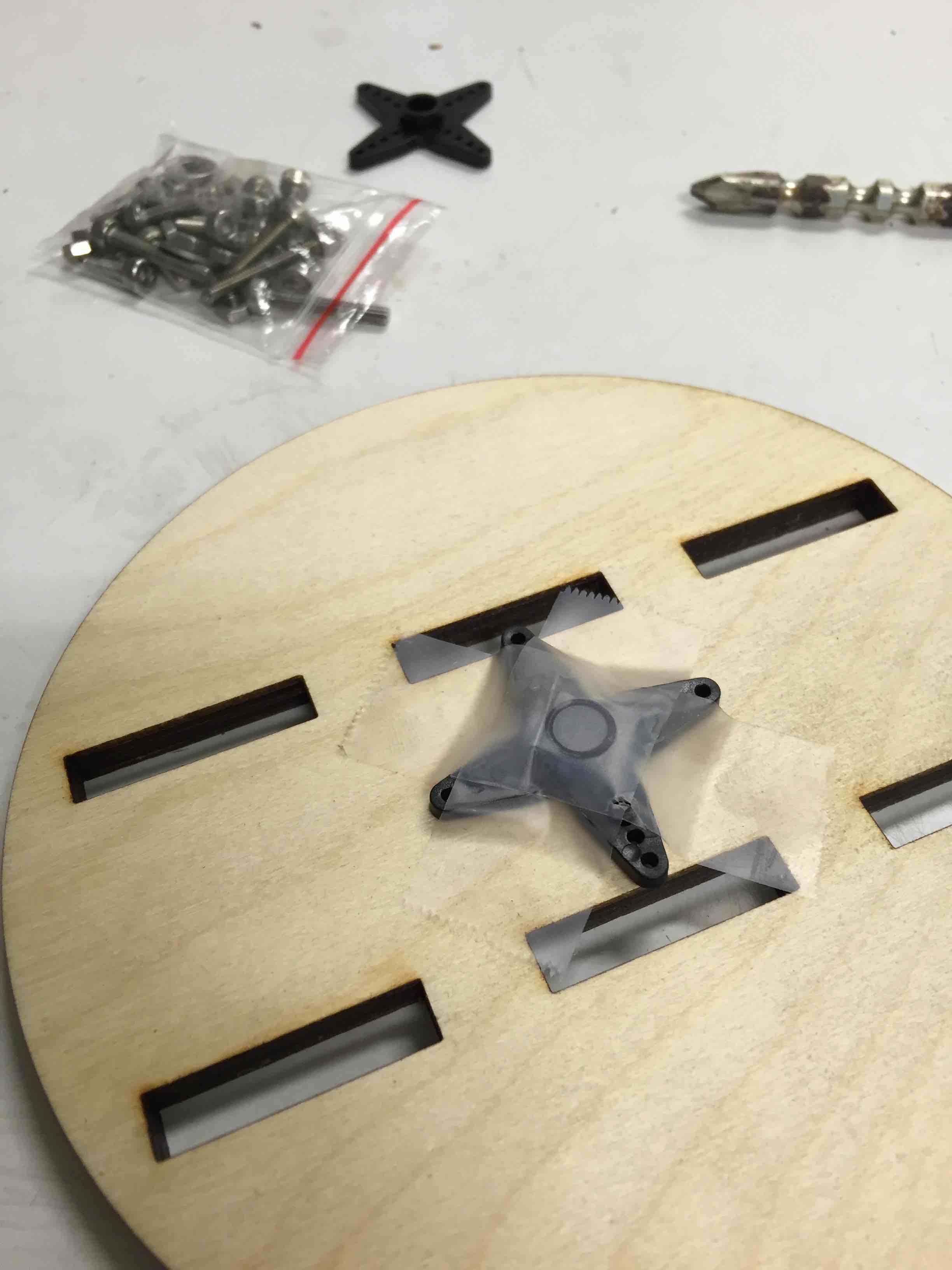
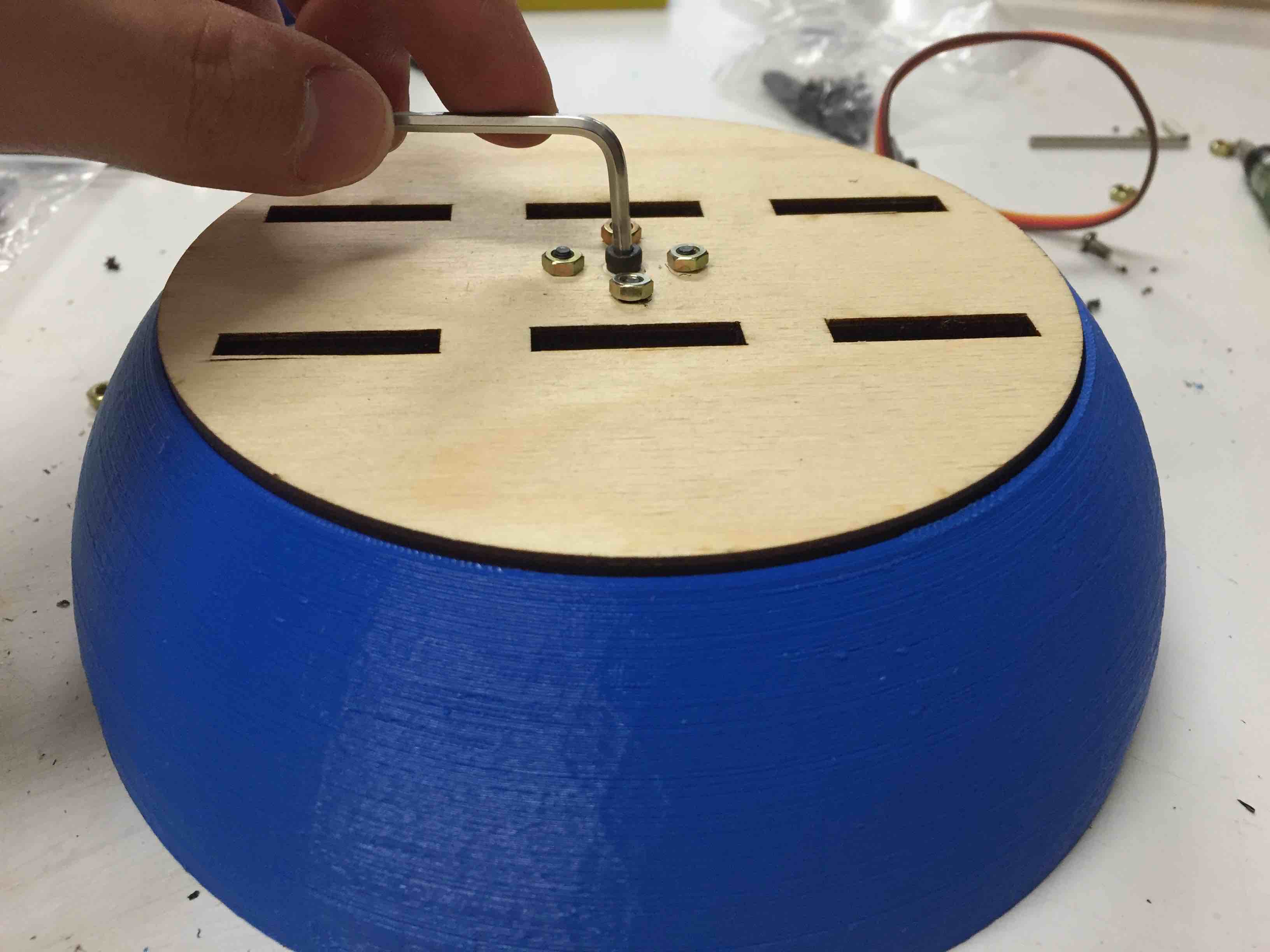
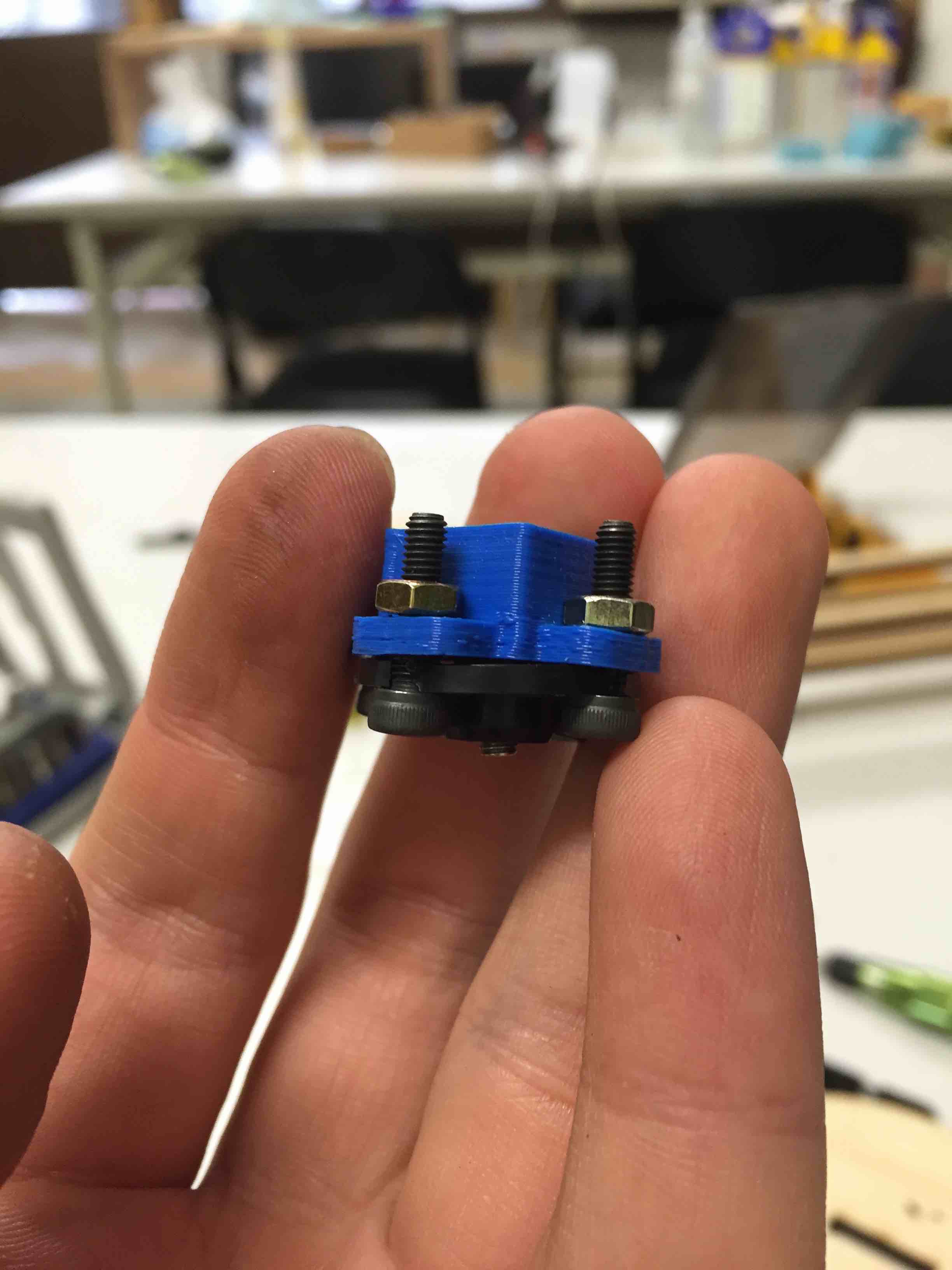
Following this elegant slew bearing design by jorgerobles, I tried to draw and print a new version base with slew bearing which should need 6mm BB balls.


Again, it can berely move because of wrong flowrate of 3D printer, I should calibrate it first and slightly reduce the ball orbit diameter. It seems really silly for me to do additional processing to let it work.
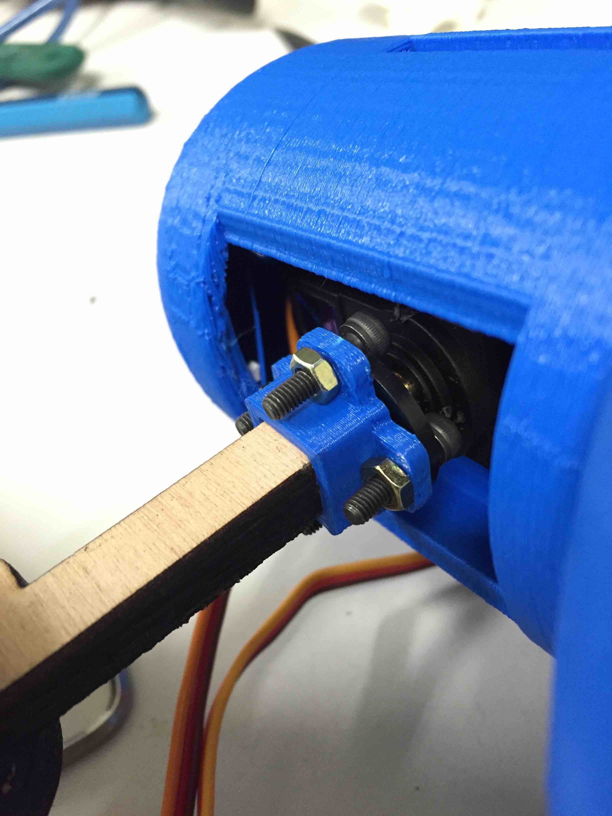
I added an M4 hole to fix the neck and connector.


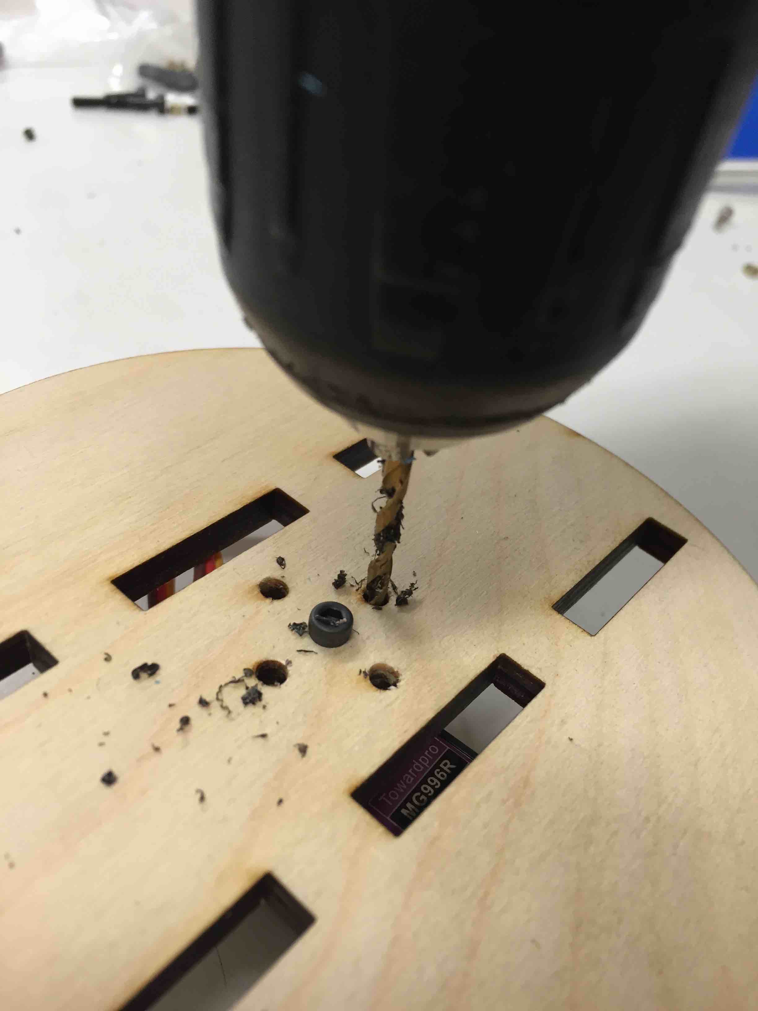


I did not try to drive it yet. But, in these processes, I found out some issues.
The base needs slew bearing
In the first design version, the base frame and 3D printed base are lightly tight so that the base cannot be driven by servo. Credit to Jason Wang giving me link about simple slew bearing design.
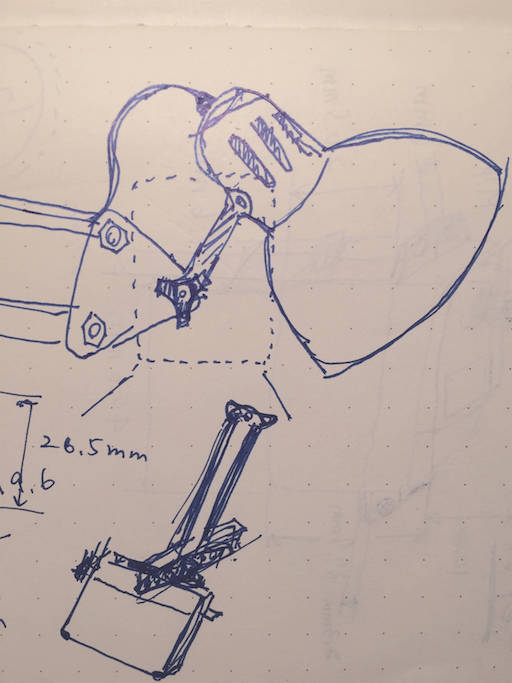
Re-design neck structure
It cannot be well connected between laser cut frame and 3D printed mount.
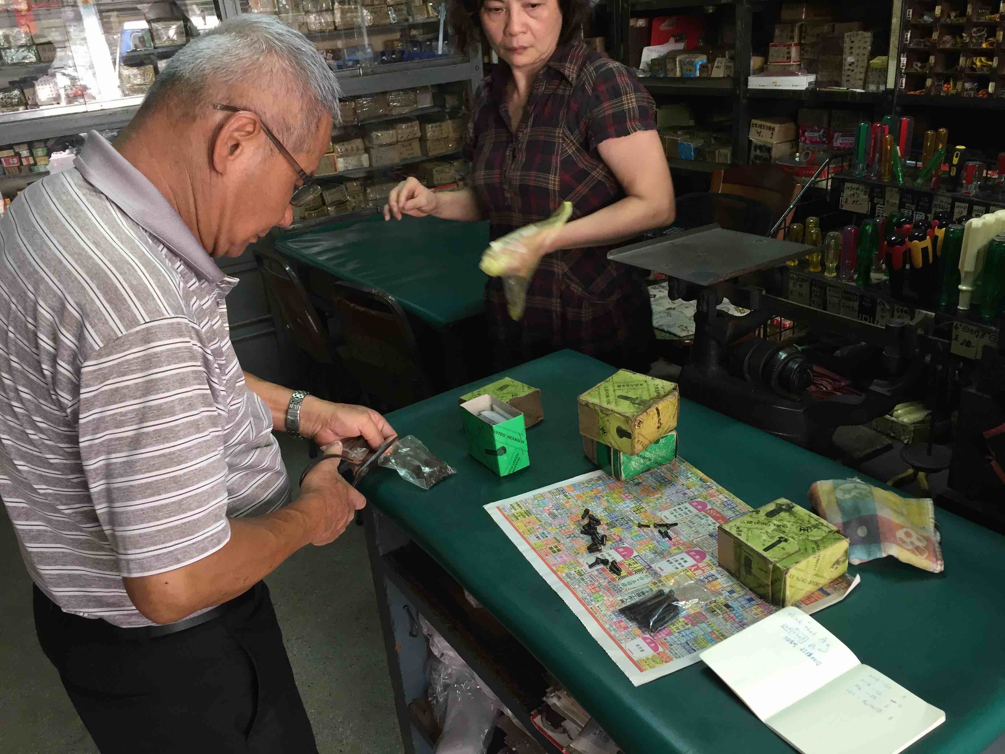
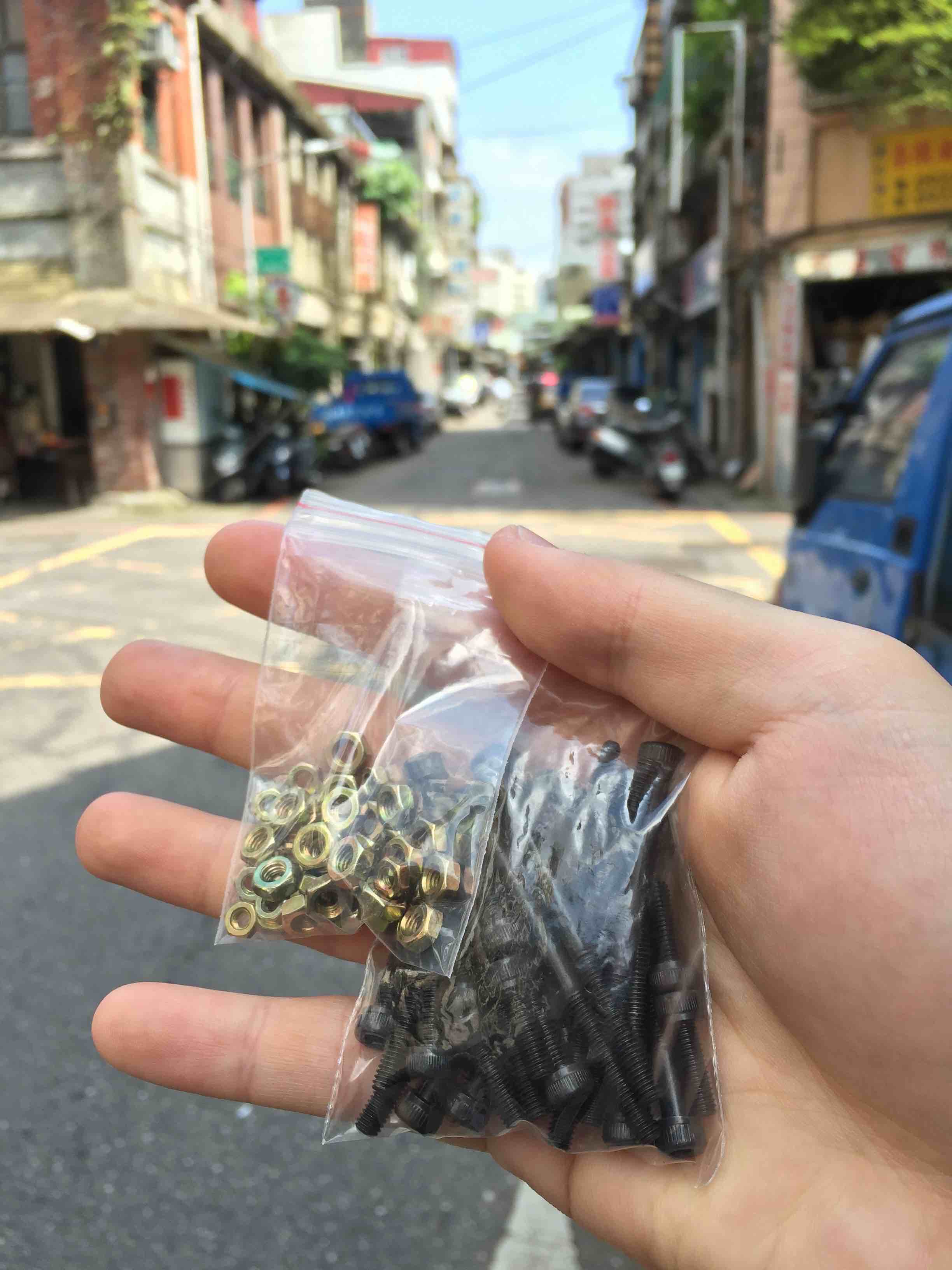
It is quite easy to buy any kinds of materials in Taipei or even in Taiwan, and the most famous spot in Taipei is Xingcheng St. (興城街), as known as blacksmith street in the past. Here you can get screws, springs, or any metal process materials.
| size | number |
|---|---|
| M4 - 50mm | 10 |
| M4 - 12mm | 12 |
| M4 - 30mm | 5 |
| M3 - 12mm | 10 |
plus all nuts, total about $35
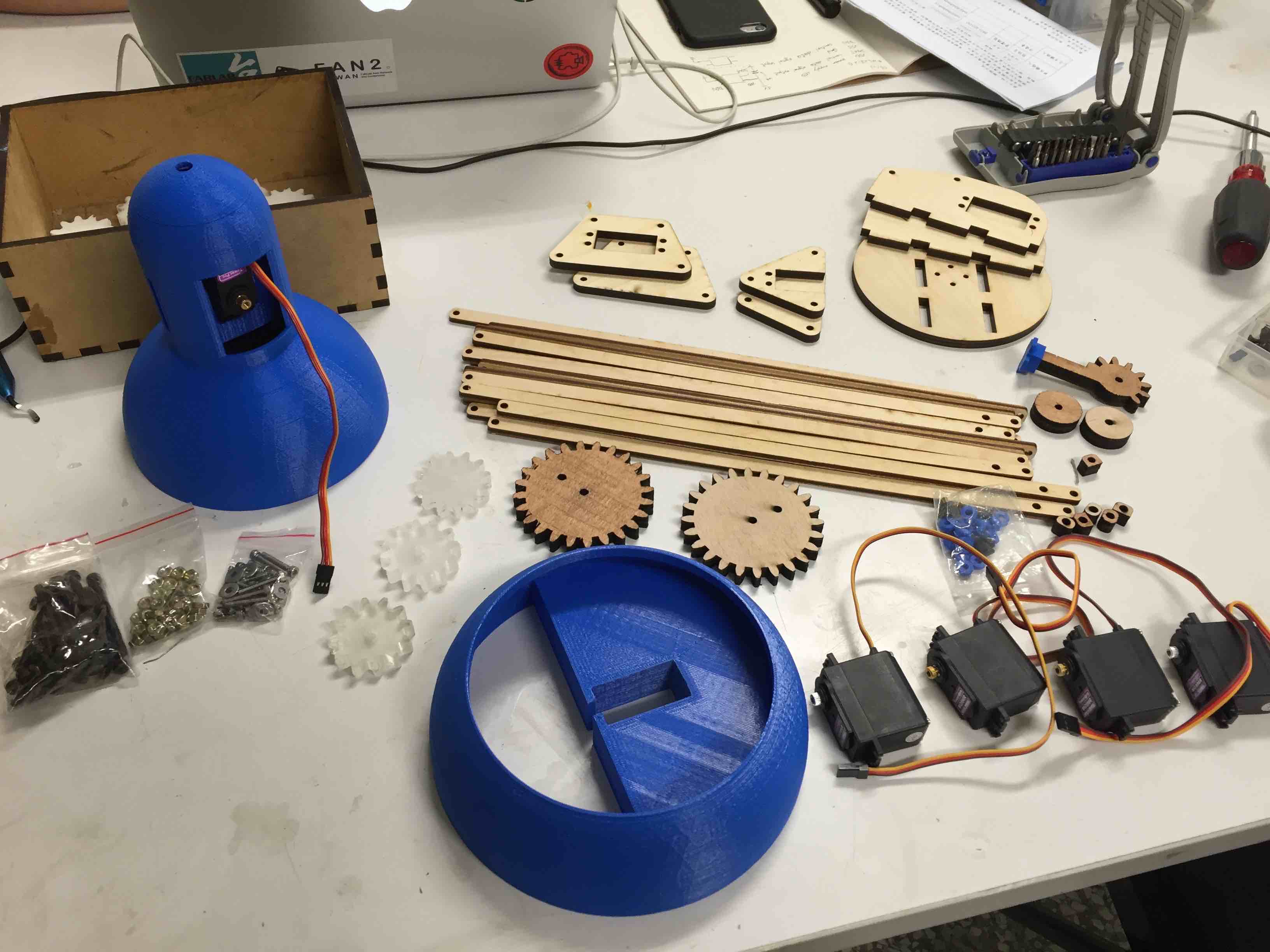
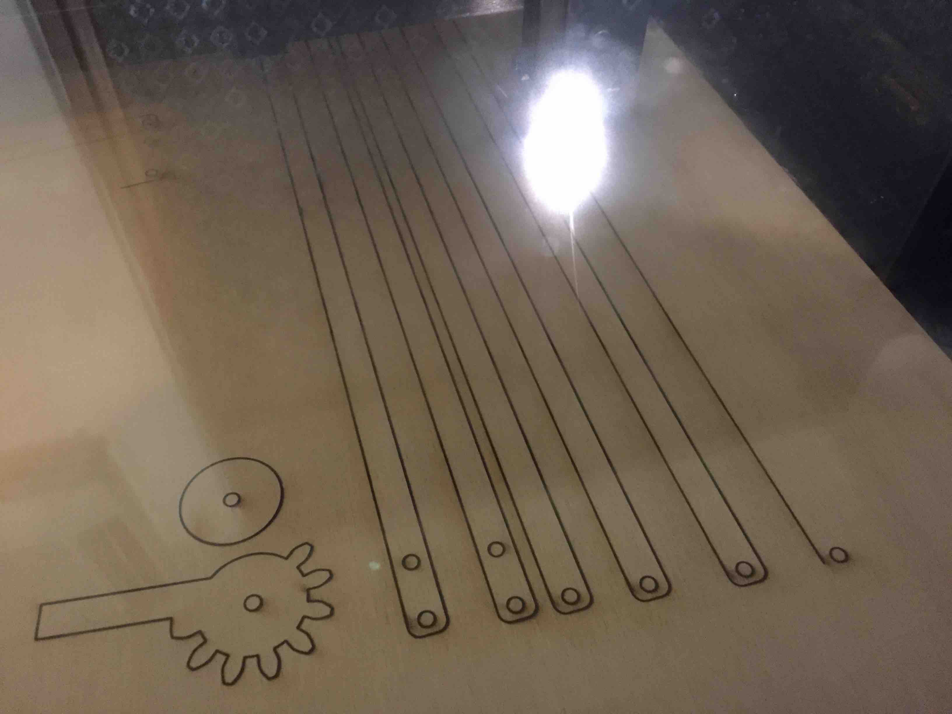
Exporting sketch from Fusion 360 to vector, I designed two different kinds of thickness (with 6mm, 9mm plywood). In cutting, I had to take care about wood grain direction which could let structure weaken.

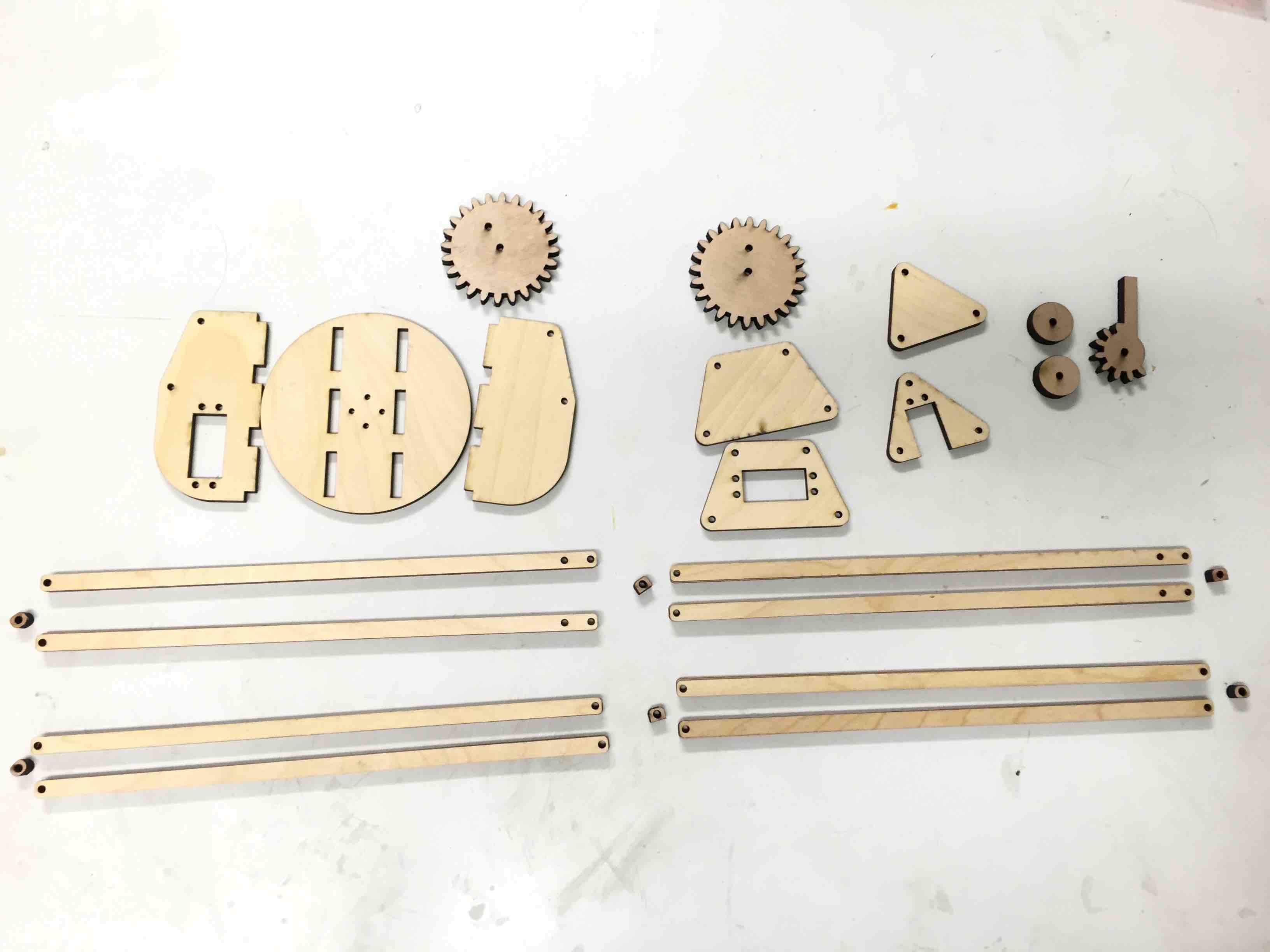
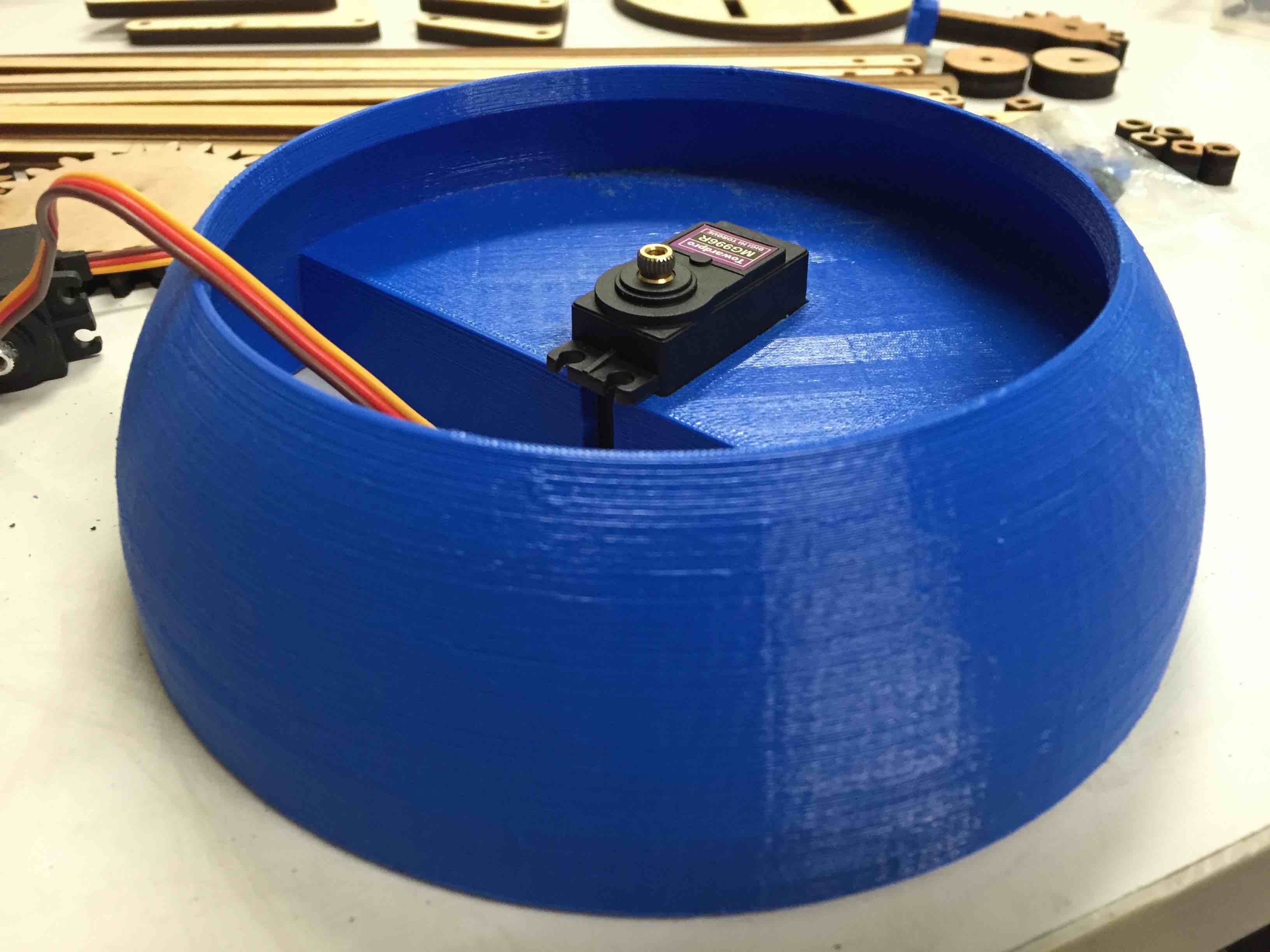
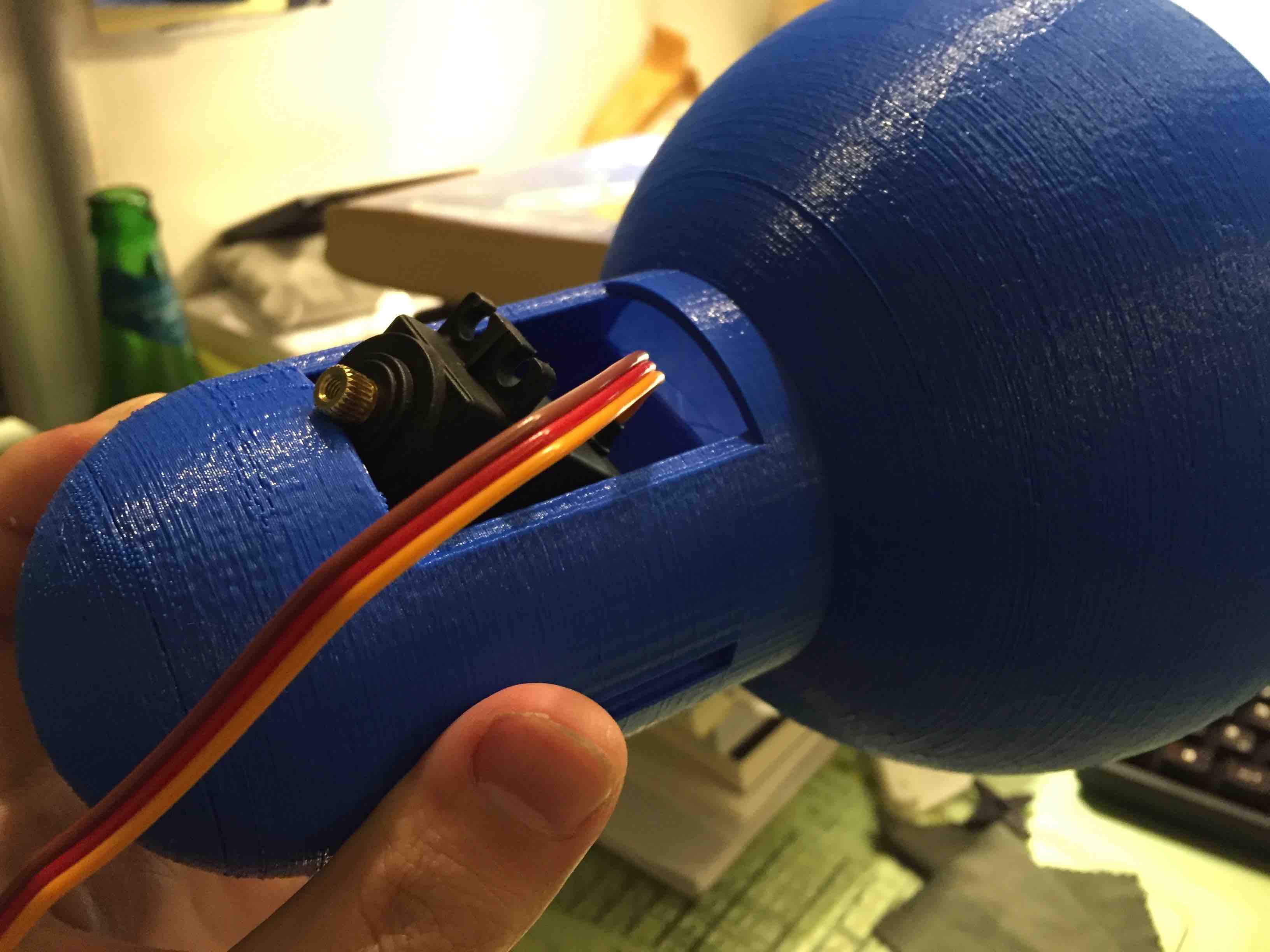
There is a issue of fitting servo to the frame since that I did not consider about the cables.
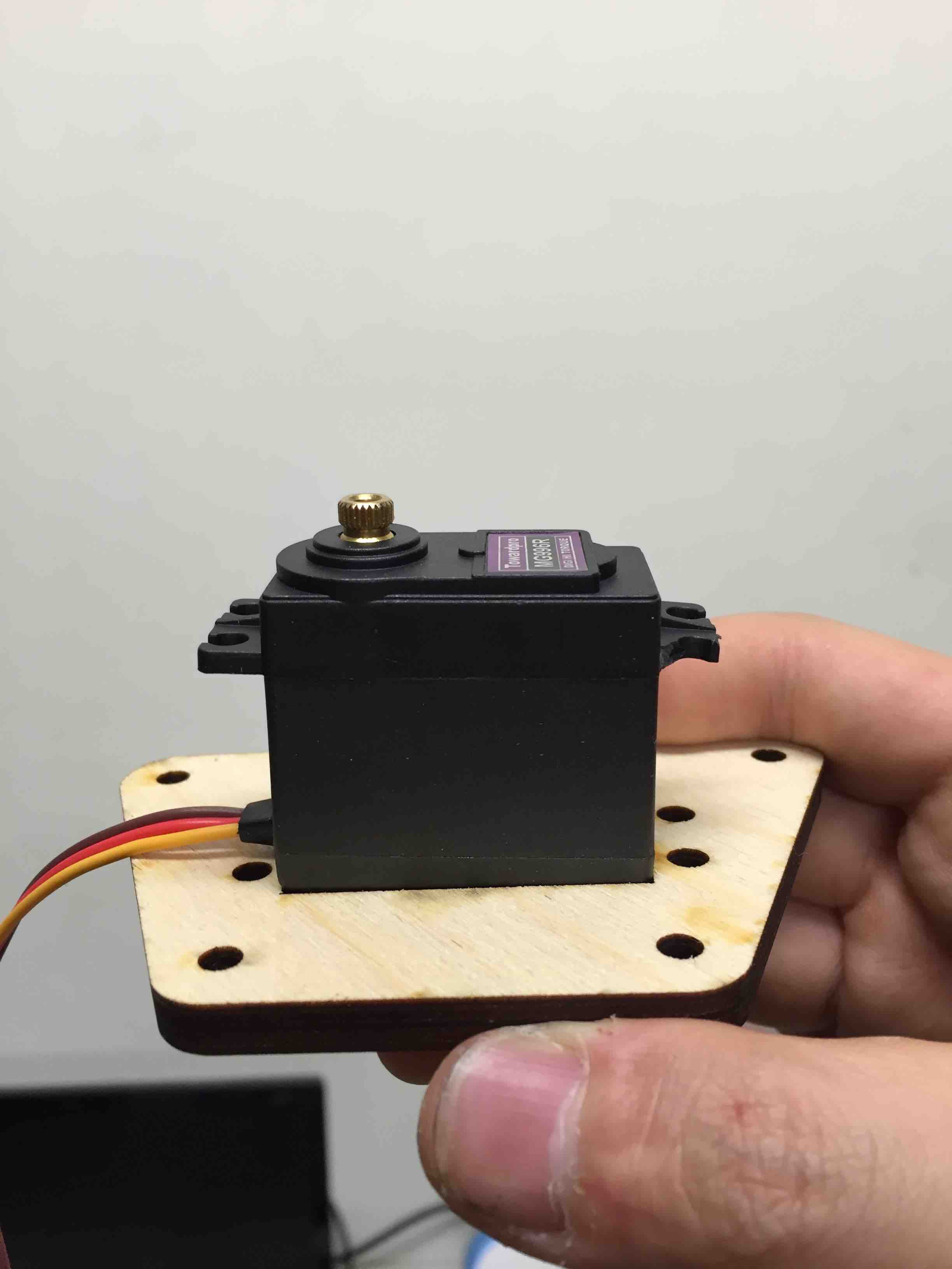
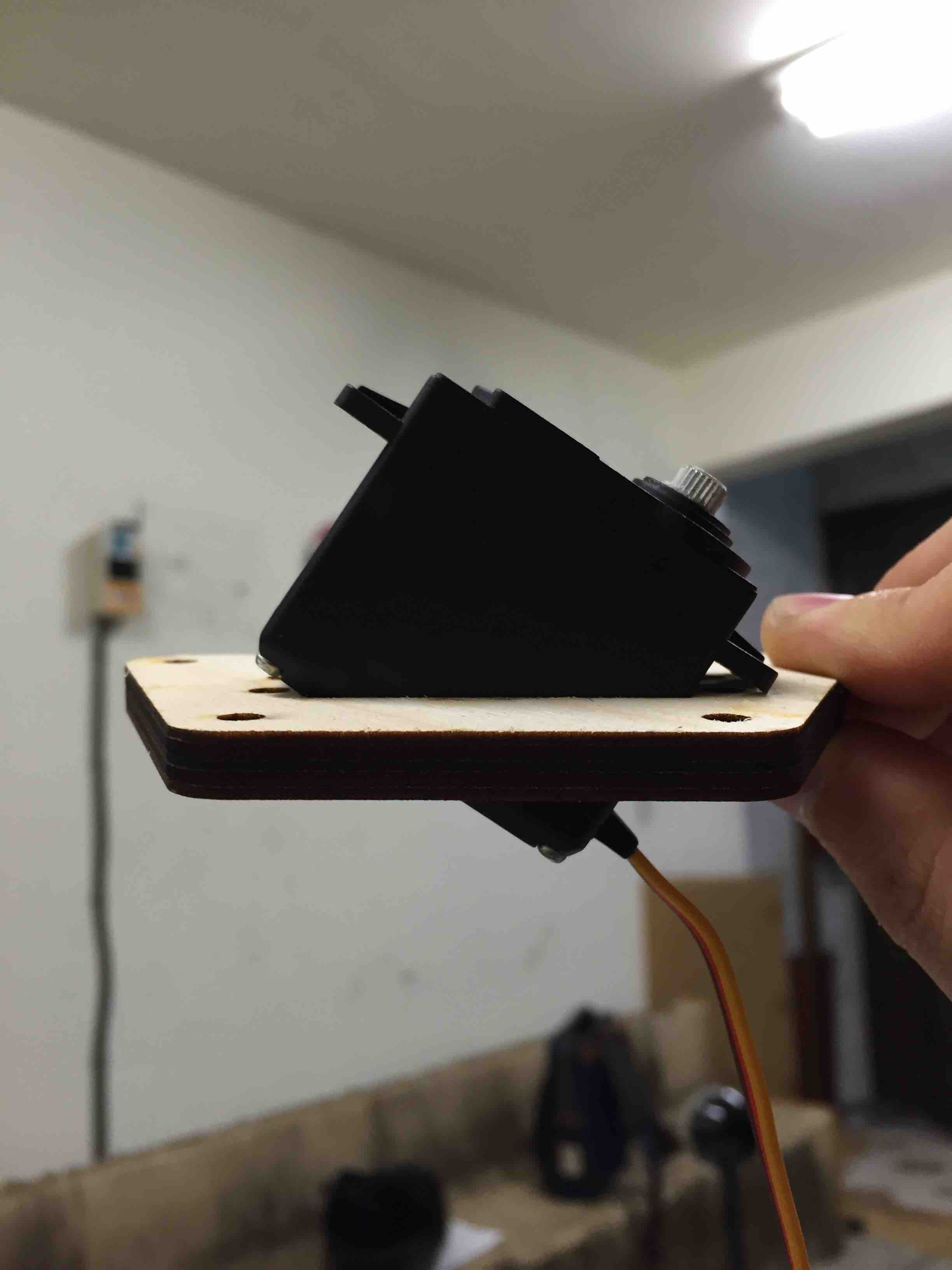
So I draw second version with large mount and it worked!
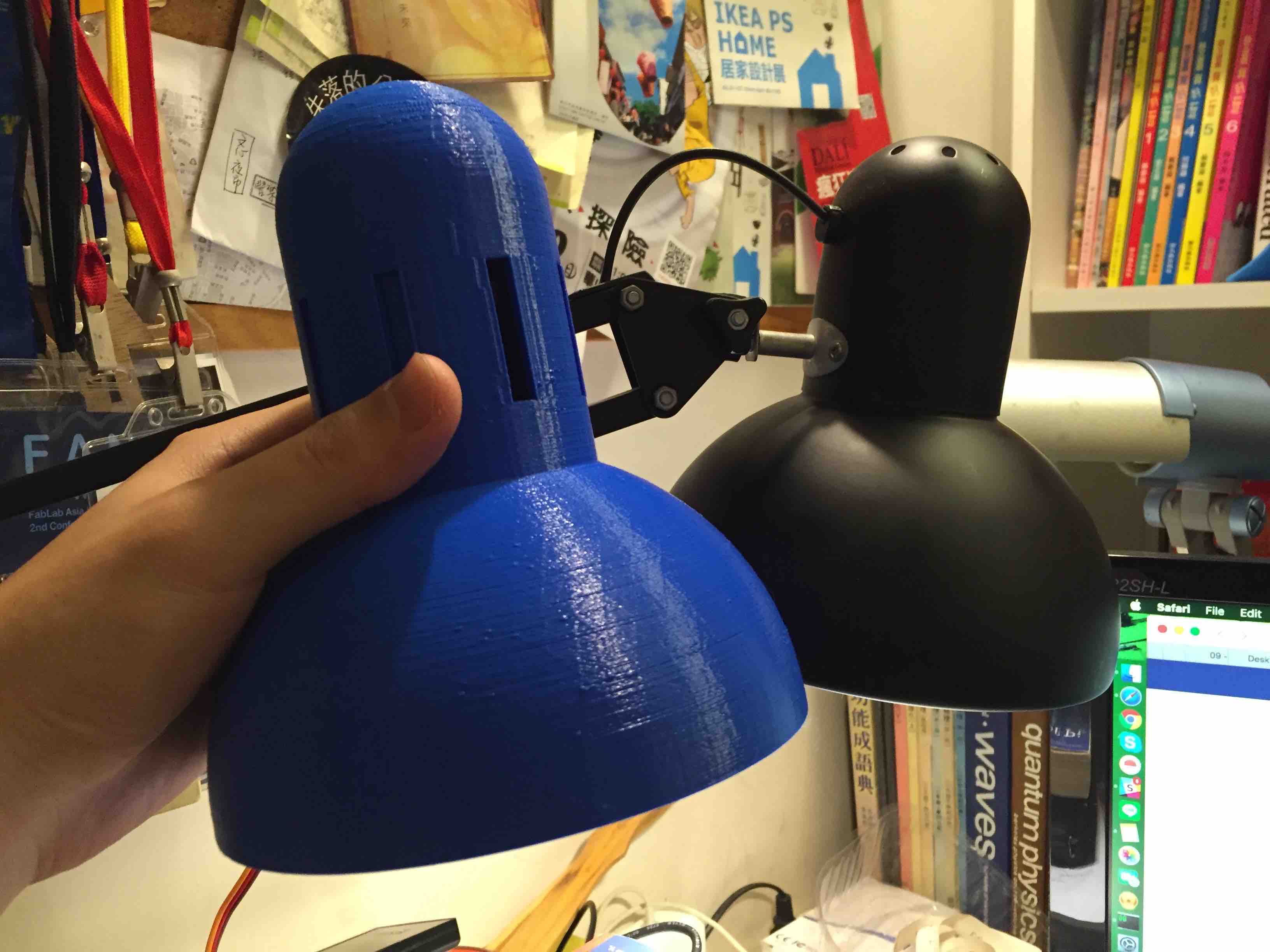
In week2, I have already designed the prototype of DA lamp head/lampshade. Then, with simple modification, I could mount the servo in it.

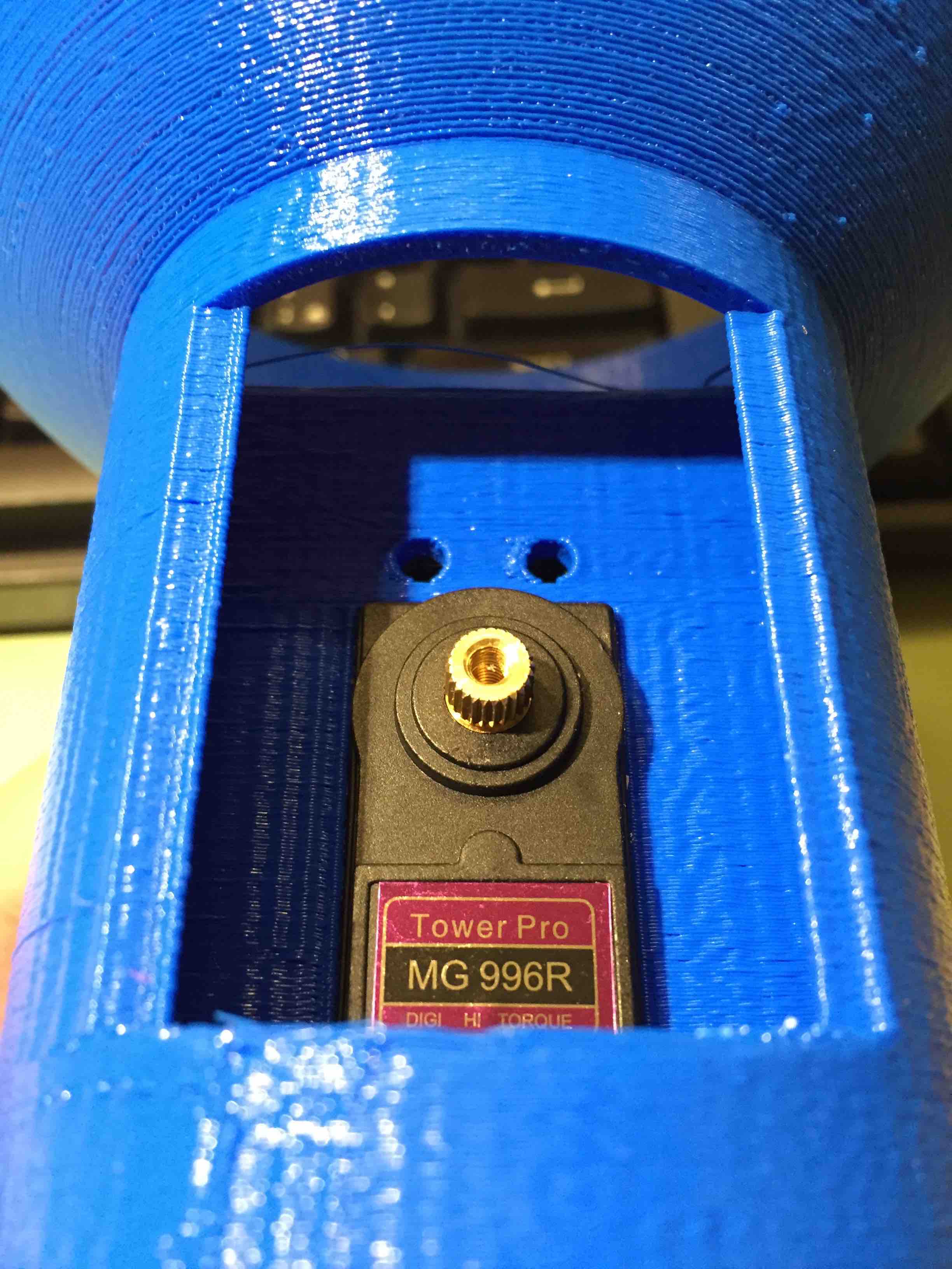
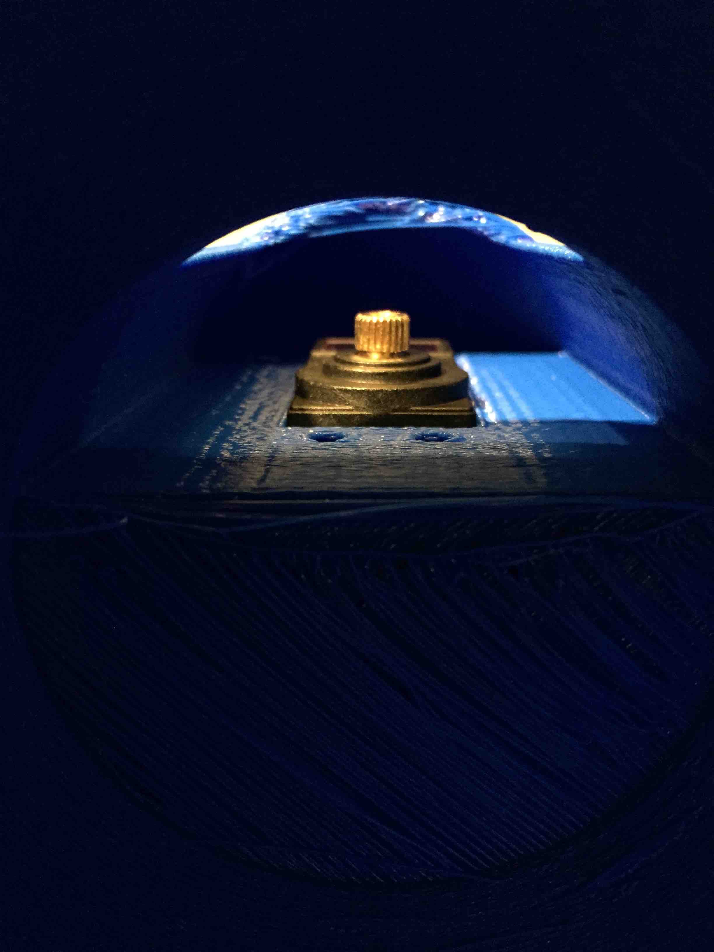
Printing with my homemade Prusa i3 (took about 8-9 hours)
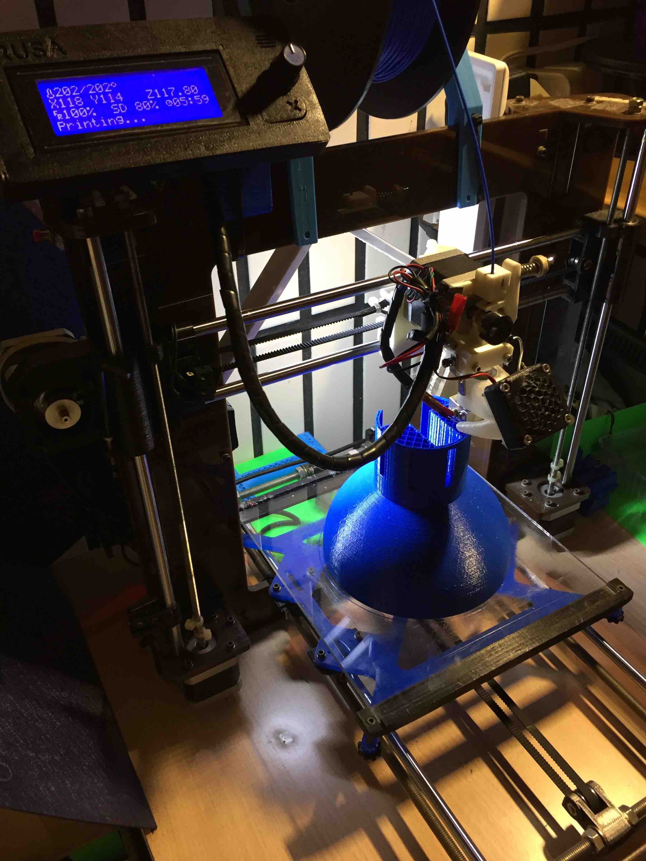
Because of my printer without flowrate calibration, it seemed a little bit tight to mount.
See week12.
The point is that I have to simplify the design so that each lab would have chance to easily make a lamp-like robot.
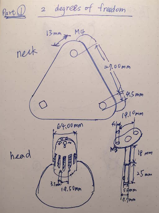
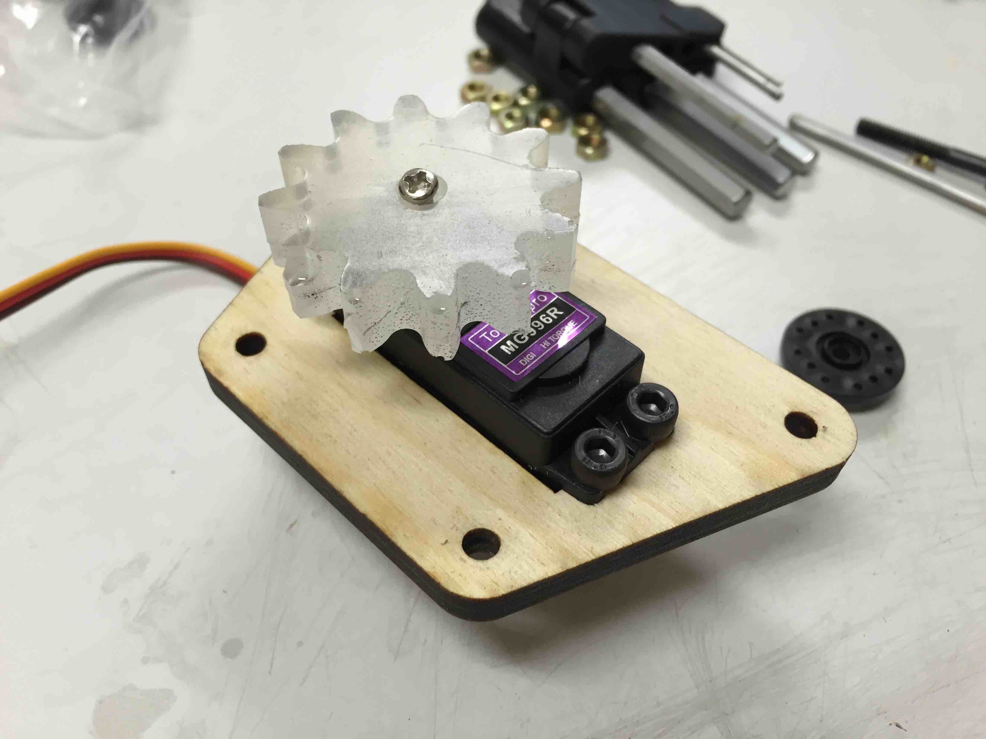
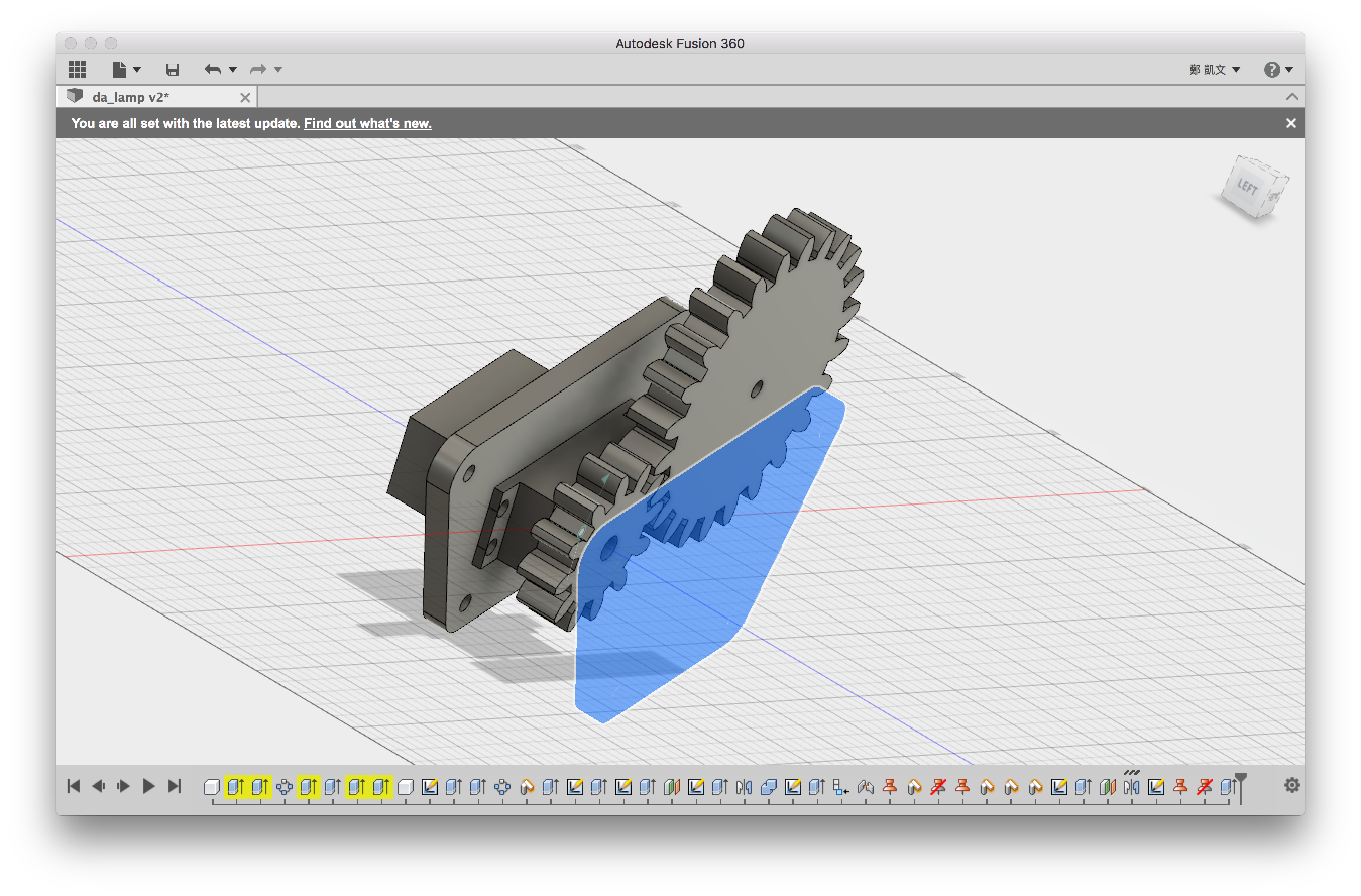
I started with Fusion 360 to make CAD file. With couple researches, I realised that hobby standard servo arms/horns could become the most difficult part to design. There are standard size of servo bodies but not for arms/horns which are customised in every companies. So I was going to make casting exopy gear to mount servo first, and then, for major joints, to design reduction gear in 1:2 ratio.


and here is the shared preview link: http://a360.co/24hN9Yf
I am interesing in physical personal assistant from childhood. Especially I like a racing cartoon called Future GPX Cyber Formula, which has a bot with AI in car helping leading character race and even becoming a friend to human being.
One day, at Fablab Taipei, we were discussing about documentation issue and where we could have better documentation tools to let people leave and share their experiences and knowledge to the space.
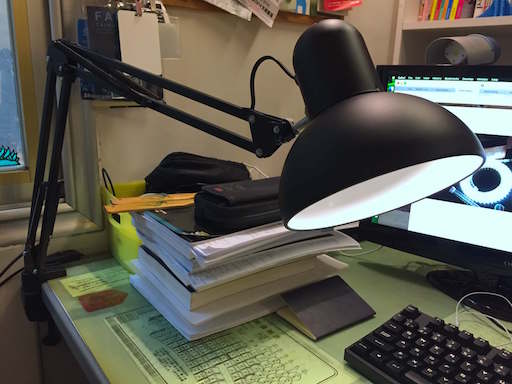
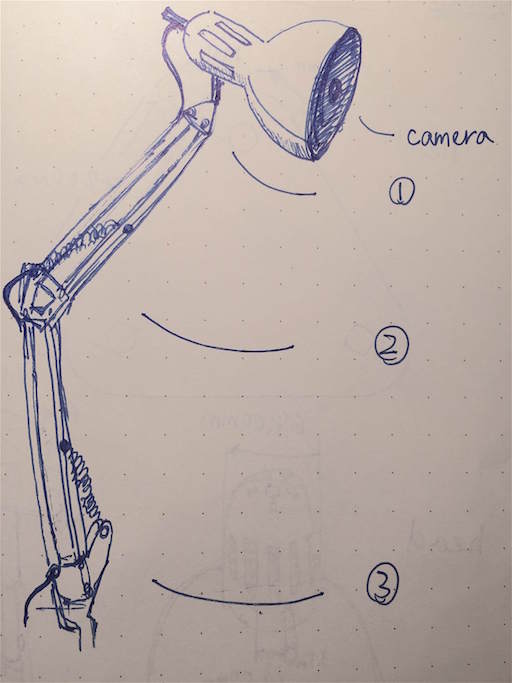
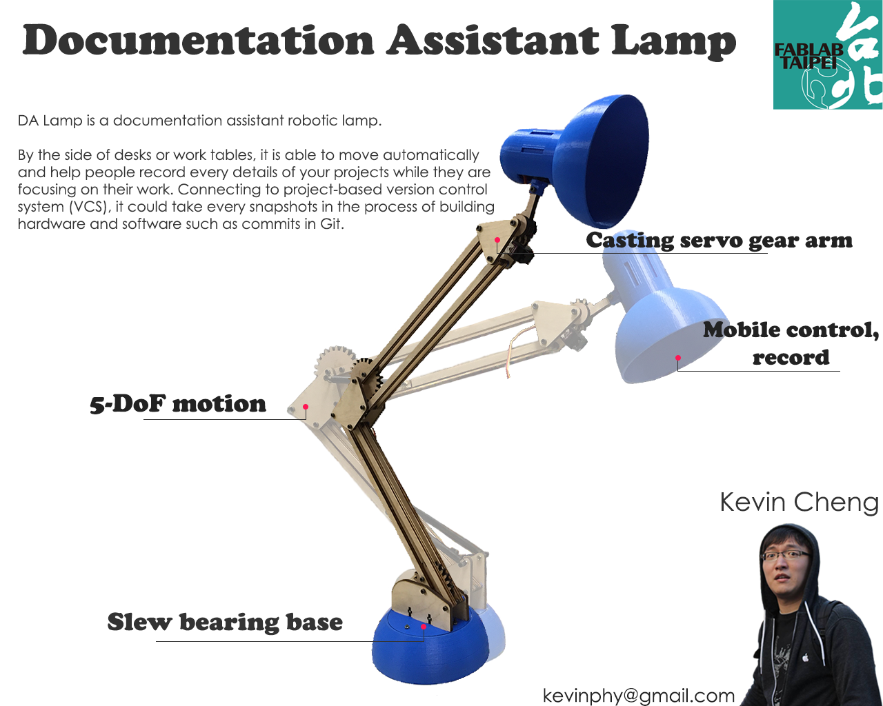
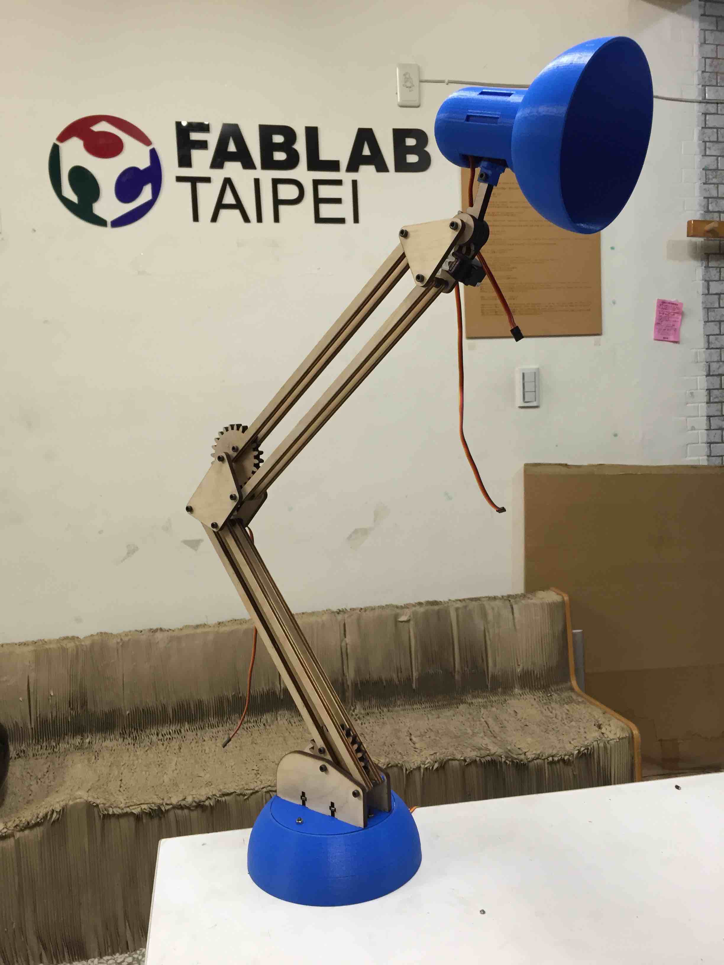
So, looking at classic tertial lamp, I came up with an idea like Pixar Luxo Jr. and I have decided to make or even redesign this lamp to let it help us do the documentation such as taking photos of your projects automatically. I do love this idea because it will become an useful personal assistant which is my dream from childhood.

I am going to mount several servo motors on it, and redesign many parts to let the lamp move smoothly. It might track your projecet object and motion. You could click some button to take photos of projects or maybe it would move and shoot automatically. Most of all, it should upload to your personal repository without your commands.
There are few robotic lamp projects on Instructables, but by far none of them are going to make lamp help people like this way.