WEEK 7 - Computer Controlled Machining
TASK:
* Make something BIG.
* Design a parametric shelf
* CNC Milling
* Assemble design
Design a parametric shelf
Software Downloads: Rhino
Download generated Rhino files: Parametric Shelf_02.3dm
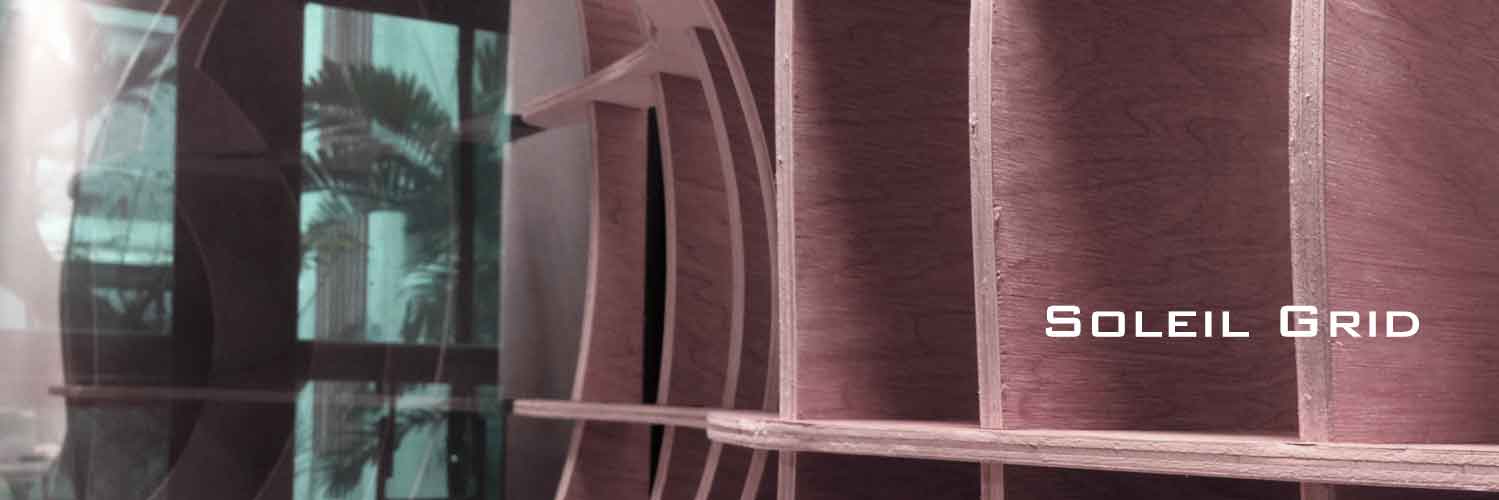
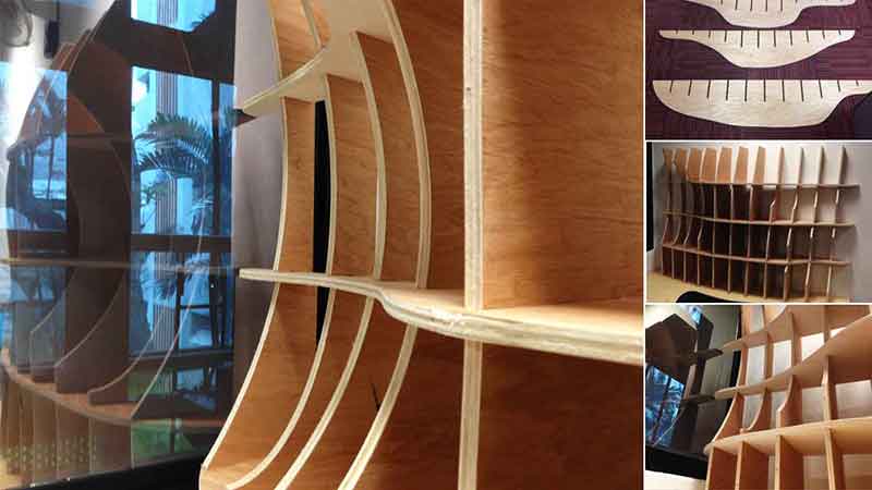
Parametric Furnitures explore the possibilities of interconnectivity between form and structures, computational design and reality. They are commonly characterized by multiple elements forming shapes found in nature or formed by specific needs of the user. The Parametric Shelf entitled Soleil Grid was derived from the need for an office shelf that allows light in from the window and also unobstructive to a colleague seated nearby.
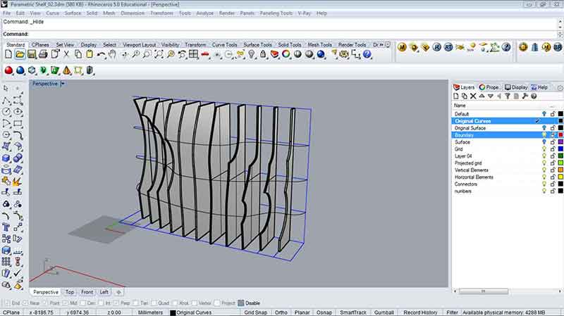
The main intent for the designing of Soleil Grid is to ensure maximum tapering at the side of the shelf and maximum depth at the center for storage. This was achieved by creating a cross-like surface (as shown in image below) that bulges at the centre and tapered at the edges over a grid comprising of 250mm by 125mm rectangles.
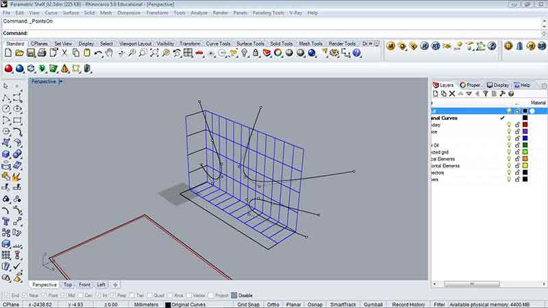
Here are some of the critical steps:
a) Create a grid of 250mm by 125mm and place them behind 3 curves tapered to the sides of the grid. The curves were created by drawing them flat and use the command "Points on" to turn on the ponts on the curves to adjust positioning.
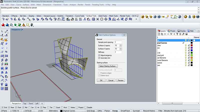
b) Next, use the command "Loft" to join the curves to form a surface.
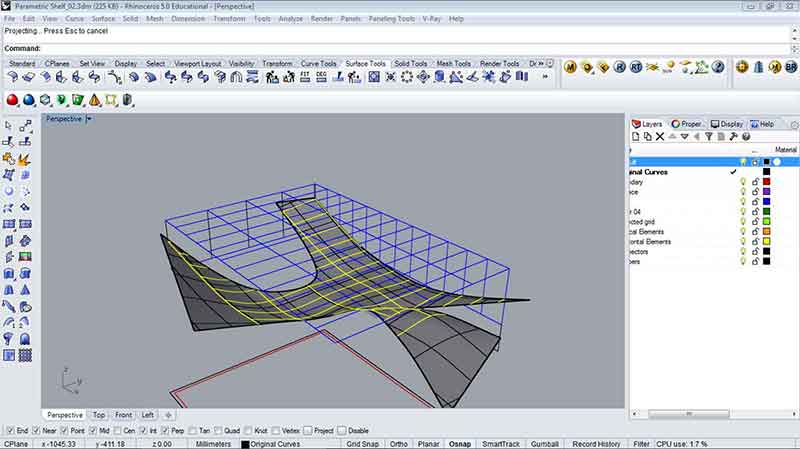
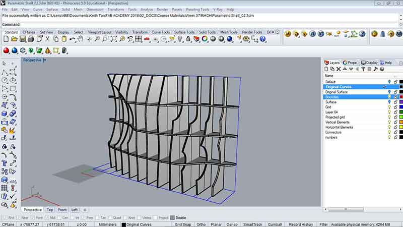
c) Now, project the grid onto the surface. This can be done by rotating the model 90 degrees so that the grid is either on top or below the surface. Run the command "Project" and set the grids onto the surface.
d) Next, loft the vertical grids with the vertical grids that were projected onto the surface. Remember to turn the surface off or hide it. Execute the command "Extrude Surf" to turn the vertical surfaces into solids. As the shelf was designed to stand on it's own, additional arcs (representing voids) were introduced for additional structural support. Alternatively, this can be done by re-creating a surface that includes the arcs.
e) Repeat step d to create the horizontal elements.
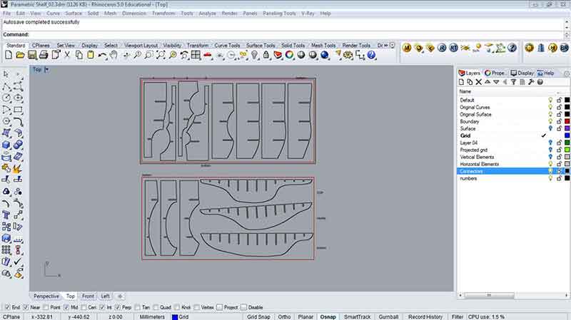
f) Flatten the elements by selecting the surfaces and execute the command "unroll". Once the surfaces have been unrolled, key in the command "silhouette" to abstract the edges of the unrolled surface. This is to ensure that only the edges get milled. Annotate and number the parts for accuracy. Slot joints of 11.6mm were also added at this point.
CNC Milling
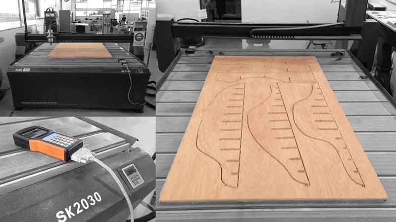
Miller model: SK2020
Material: 8 x 4 feet plywood.
Average thickness: approx. 11.7mm
Press-fit setting test determined around 11.5- 11.6mm to be ideal for slot widths.
Map of working process:
Export DXF files from Rhino> Open up files in Master CAM to configure, analyse and add tabs> Export files for milling > Open files in CNC-Change to convert as NC files and send to machine> Mill!!
Here are some of the critical steps involved:
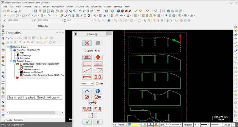
a) Open up dxf files in Master Cam, analyse drawings for errors and delete duplicates. Next, proceed with chaining the mill and prepare the tool paths. Below are some critical settings for toolpaths contouring:
Finally, add tabs to edges of the cut-outs to complete the preparation. Convert file to G-code.
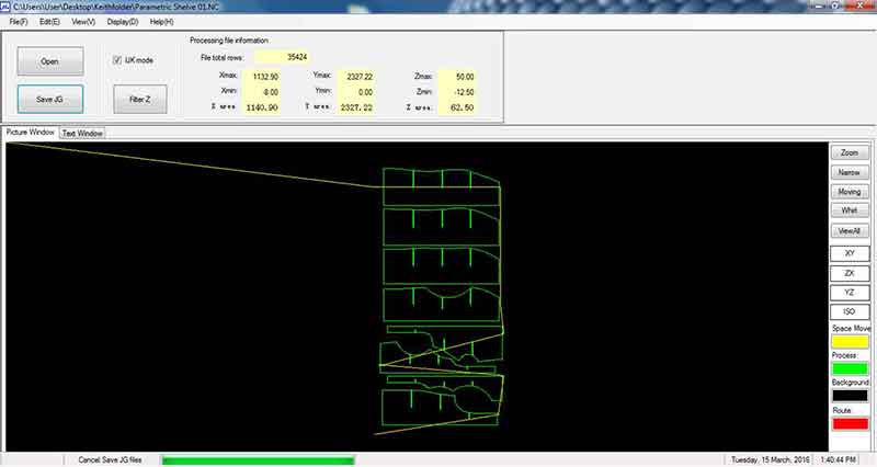
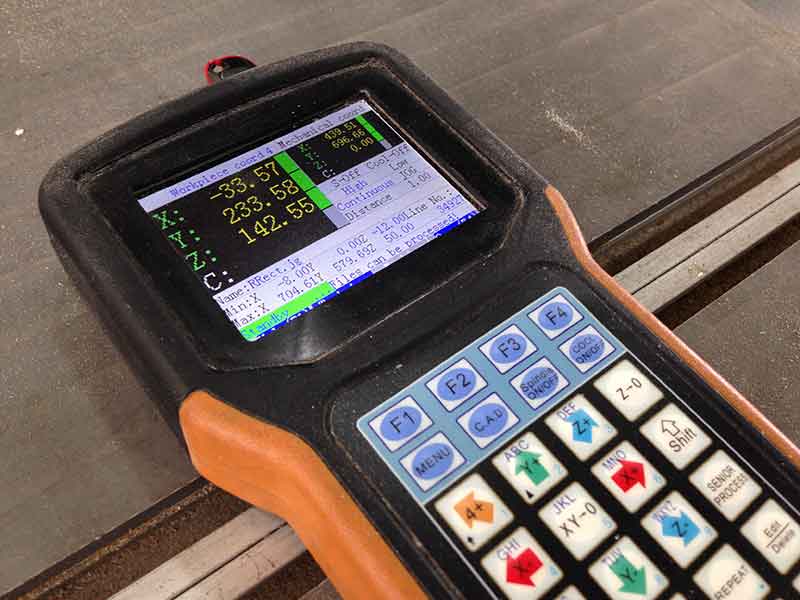
b) Next, open up the G-Code files in CNC-Change (Default program for CNC Machine) and save the configurations as JG format into a thumb drive. Next, transfer the date to Machine via the thumb drive and execute the mill.
c) Below are images of the milling process.
Assemble Design
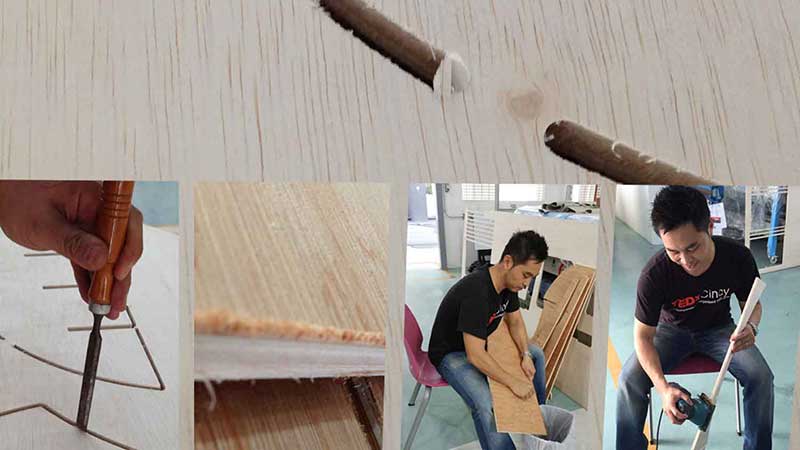
This is the stage where you will discover whether if the design works or not. Below are issues discovered during assembly:
* Tolerence of joints worked well for the parts that were less wide but definitely not so for the larger parts with deeper slot joints. Even with a mallet, it was extremely difficult to knock the parts in place.
* Usage of pen knife to scrape off excess cut-outs along edges proved to be very useful. This should be done before making final touches by sanding.
* Sanding needs to be done slowly. This will ensure finer edges and surfaces will be smoother.
Reflections
Creating a parametric furniture has always been a crave for most designers if not all. This week has definitely met the desire to design and install one. Although this has been an excellent week, there had been a few moments that could have made this project even better.
Firstly, due to lack of time and resources, the project had to forgo several designs (that looked a lot better) that require a lot more timber panels and time to complete. Secondly, the usage of Rhino to create a parametric furniture was rather primitive. This project could have been done using grasshopper to create the form as well as generate connectors and slots etc. Due to lack of familiarity with grasshopper, this was abandoned but definitely worth re-visiting. Thirdly, in regards to creating slot joints, thorough test mills should be carried out to avoid tight joints. In this case, the wider elements should be milled during test mill.
All-in-all, it has been a satisfying week! Check out my video below.


Related Projects