Exercise3 Computer Controlled Cutting...
Intro
This week, the content is on computer controlled cutting. Cutting, as the name suggest, can be done via several mechanism. The simplest of all forms are with a knife. In the retrospective view of digital fabrication, this can be done with the vinyl cutter. In FabLab@SP, we do have a Roland GS24 for this purpose. A huge amount of concentrated light can be used for cutting too, and that’s the laser cutting. In FabLab@SP, we have a few laser cutters, ranging from Epilog, Rayjet, and full spectrum. Water can be used for cutting, that is implemented through the water jet machine. To digitally fabricate a piece of computer controlled cutting, it is music to the ears for yours truly. The matter of fact: yours truly can’t cut a simple line straight.
Methodology
To use such digital fabrication machine to perform a computer controlled cut, several parameters are needed. First is the source data file. The artwork should be in the form of vector graphics, where the lines that made up the graphics are expressed in equation. Hence the computer are able to interpret the path on the vector file as a cutting path. Next, determine the type of cut, whether it is knife, laser, water jet or etc. Each of this digital fabrication tools has it’s own merits and would requires tuning.One the important requirements for this week homework is to use parametric design in the vector graphic to be used for press fit. The methodology will be explained in the sections below
vinyl cutter
I have used the Roland GS24. first install the printer drivers for GS24 on the targerted host machine. Once drivers are installed, we will be able to use the print function from the choice of vector graphic design software. The data file to be digitally fabricated with vinly cutter must be a vector.
laser cutter
I have used the Epilog Fusion 60W, The EAS 70W, and the Rayjet 30W. Each of these laser cutters had a computer tethered to it. The de facto softwr setup to use these laser cutters are corel draw. Hence, the work flow of using laser cutter in FabLab@SP is as follows. First, user need to import their vector grahpic into corel draw. From there, select the graphics, and select line width to be hairline, and then click print. Now here comes the tricky part. Each laser cutter has it's own perculiarity when it comes to the power/speed/frequency setting to be asserted on the type of materials, and the thickness of the materials. Rule of thumb, do not set high power and low speed to cut through a piece of thick material. use multiple passes of the same job instead. On epilog, to cut
3mm cogurated cardboard, the setting is 30% speed 50%power, 50% frequency.
3mm MDF, the setting is 15% speed 50%power, 50% frequency
cut with a vinyl cutter
In exercise2, we are required to use software such as inkscape to create vector graphics. I decided to continue with my Exercise2 vector graphics as the data source file for my exercise 3.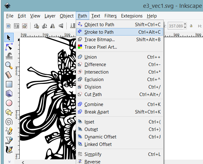
In the screenshot above, I have opened the vector graphic file in inkscape, and choose stroke to path. The net effect is strokes that represent the graphic are now expressed in vector equations.
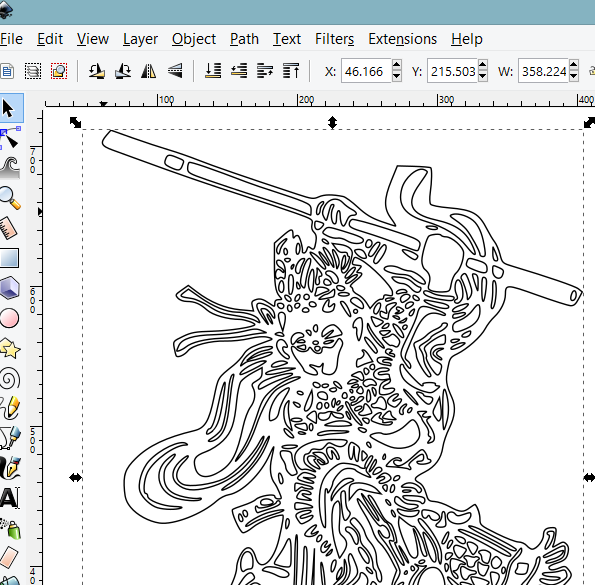
The screenshot above shows the output of the stroke to path transformation. We are now ready to send the data source file to the Roland GS24 for cutting.
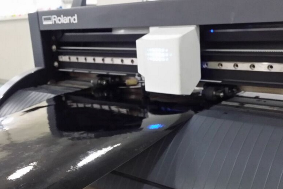
The above pictures shows the vector graphic being digitally fabricated. The vinyl cutter ready data file can be downloaded here
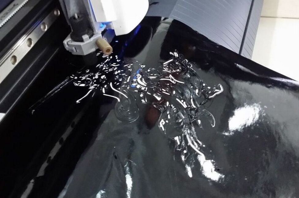
output of the vinyl cutter
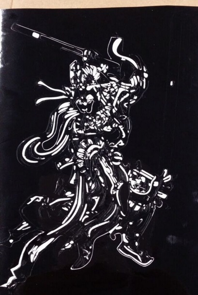
this is the final output of the data file. I realised the vector diagram is too detail and expressed in a surface area that is too small for human to further process. The output is not aesthetically pleasing. 2 choices, either reduce the detail level by cutting the major outlines, or increae the surface area of the vinly cut.
cut with a laser cutter
In the video lecturer, neil has explained about the press fit construction kit, and the recommended way to cut the slots for the press fit kit. He also mentioned about the kerf, the excess material burnt by the laser cutter that is depending on each of the machine’s setting and the material used; would require some form of fine tuning by performing cuts with a variation of settings in the speed/power/frequency. My mentor Mr.Chew has done a significantly detail explanations of the power setting for the laser cutters in FabLab@SP. Since he has done such a good job and share the information, therefore I shall not reinvent the wheel.parametric design for press fit kit
Prior to neil’s video lecture on press fit construction kit, I have designed some slotted shapes in inkscape to be used with the laser cutter. Kerf is one thing the perfectionist would want to try and error to get it perfect, such that the output will be perfectly fit. During design time, this was taken into considerations.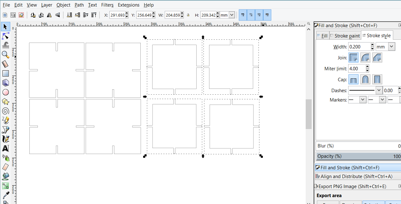
The above screenshot is the output prior to neil’s lecture, which is done with several union and intersection operations, then the lines are group and then duplicate to make exact copies. This methodology is not recommended because the design is not parametric, i.e if the kerf is too big and the design needs to be modified, I need to modify all of the slots duplicated, which is time consuming.
During the video lecture, neil mentioned about several type of slots design and one of them being the chamfer and the benefits of designing slots with chamfer to allow for tolerance of kerf. He also mentioned that the design for this week homework has to be parametric. The boon of a parametric design is, the moment I knew the kerf is too large (or small), the design of the slot only need to change once and the changes will be propagated to the rest of the design. I have decided to ditch my design and recreated a new one following neil’s video lecture.
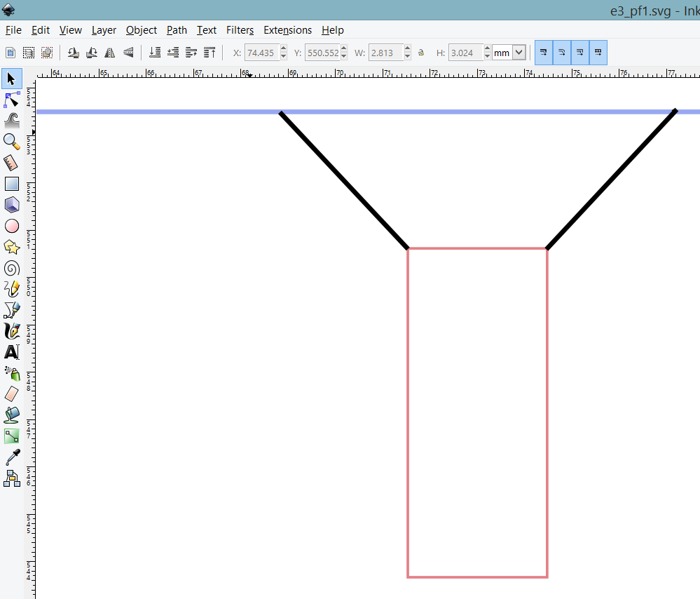
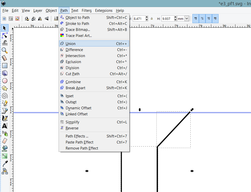
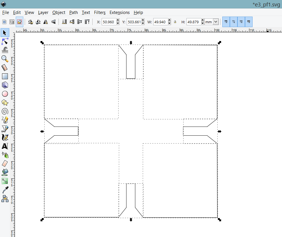
I started off drawing a chamfer with the help of standard shapes, and lines in inkscape. For some weird reasons I could not perform a erase line on the union of the 3 objects as per describe in the screenshot above. Thus, I have decided to draw a chamfer with standard line tools from inkscape. I have taken extra precautions to ensure the distance between the slot is at 2.9mm, taking into consideration the kerf of the laser cutter is 0.1mm (at both sides of slot), this will give my slot a very tight fit. The design is per depicted in the screen shot below.
The standard lines are then union to make it a singular entity for easy manipulation, as per describe in the screenshot below.
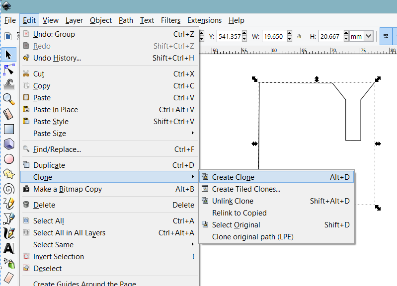
The trick to create parametric design in inkscape, is using the clone method as depicted in the screenshot below.
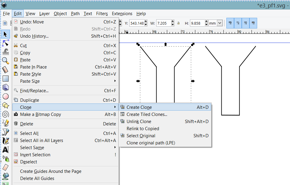
The chamfered slots are cloned thrice to create a 4 slots on a standard shape piece as per describe in the screenshot below. So in the event of a change in dimension, I only need to do it on the master entity, and the changes will be propagated to the clone pieces.
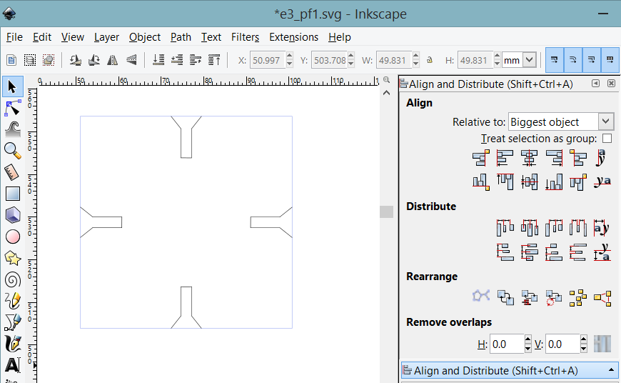
For some weird reason again, I could not erase the non-overlapping line of the unioned clone entities and the square shape entity. Draw by hand, I must. The following screenshot describe the manual drawing. Guess what, I could not draw a line straight with inkscape too. No amount of digital fabrication can be my saving grace.
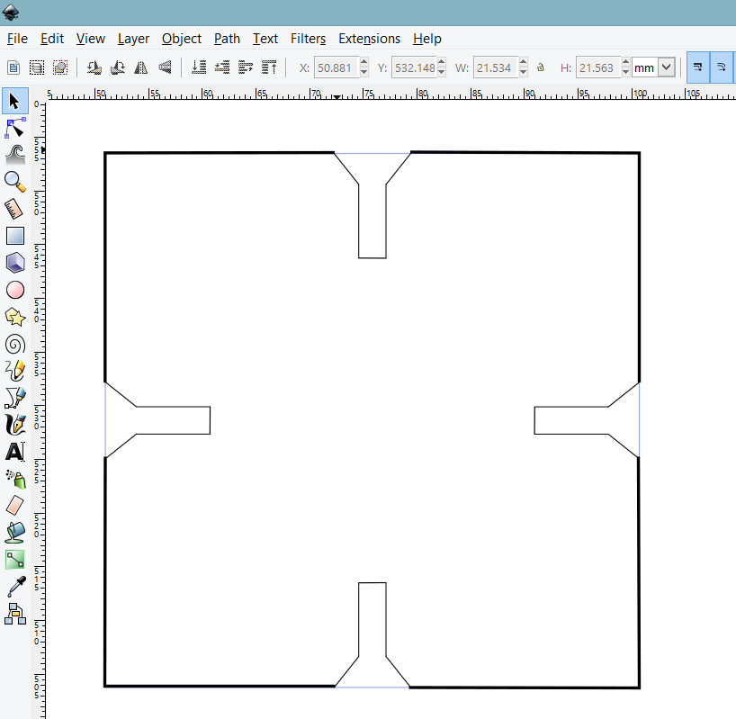
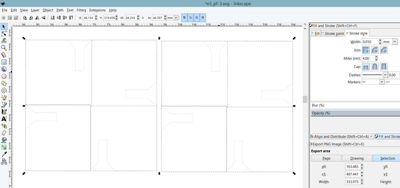
The following screenshot describe the chamfered press fit kit I have designed that is ready to be laser cut.
The press fit kit laser cutter ready data file can be downloaded here
I also took the liberty of creating another design where it is entirely parametric, not just the chamfered slot. The difference from the first design is one quarter of the new design, which consist of a chamfered slot and and two lines perpendicular are cloned thrice.
The alternate press fit kit laser cutter ready data file can be downloaded here
laser cutting and testing the press fit
The above picture is the laser cutting in action on the epilog laser cutter
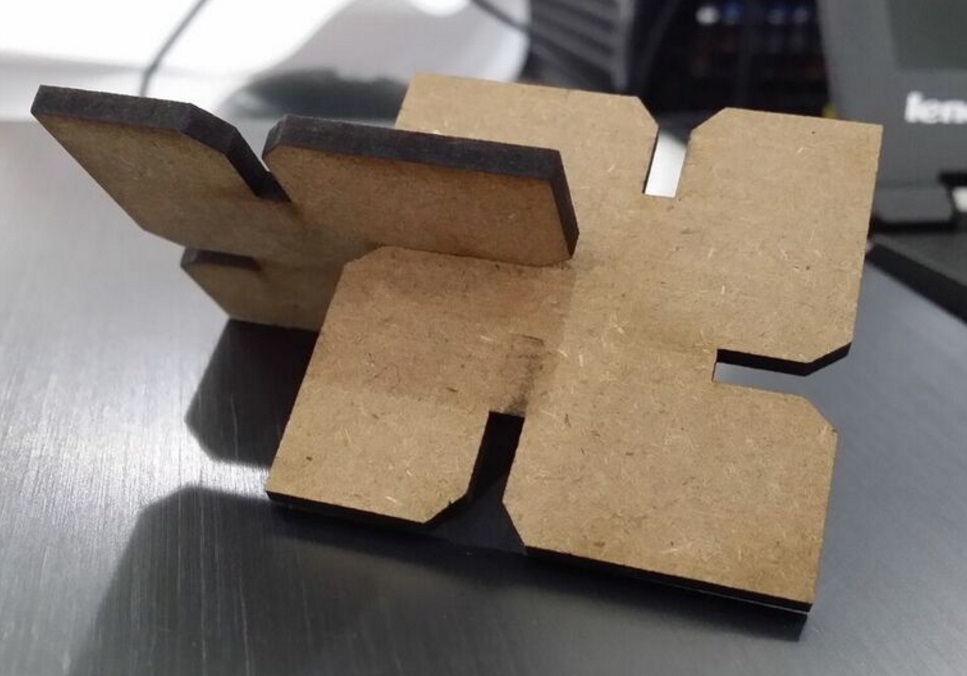
The above picture is an assembly of 2 pieces of square shape with the chamfered slots in 3mm MDF.
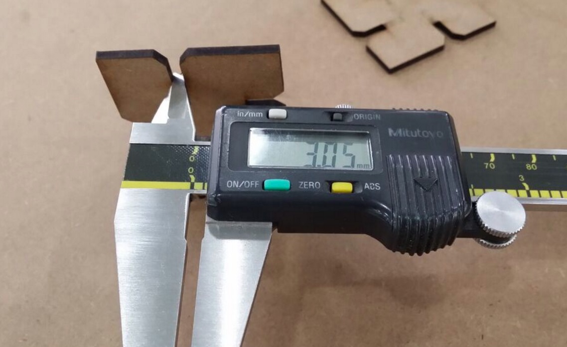
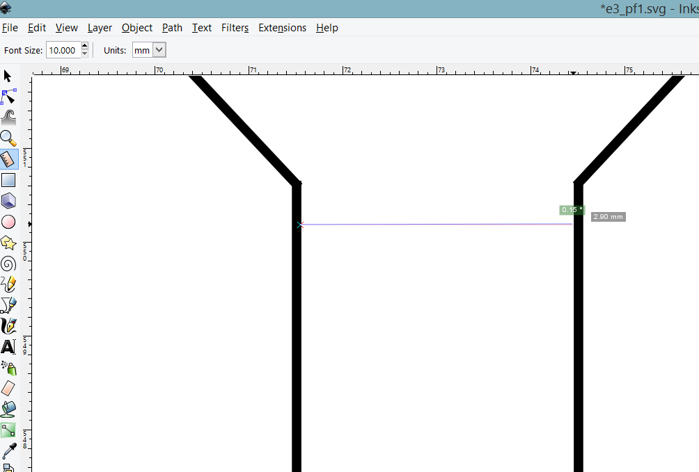
The above picture describes the measured width of the chamfered slot.
In design, the width was set as 2.90mm (for a 3mm thick material), after several rounds of laser cutting and brute-force the perculiarity of the laser cutter, the measured width is 3.05mm. The difference is 0.15mm, or 0.075mm at either side. Not perfect, yet. It took me a coule of tries with the laser cutter to arrive at a conclusion: high speed, low power, and multiple passess will result in smaller kerf, but at the cost of machine time spent on the laser cutter.
Following the newly discovered methodology of brute-force-ing to get the perfect kerf, i have experimented with 3mm cogurated cardboard. The 3mm cardboard stock we got did not pass the pinch test, but worthy enough to rest an iphone.
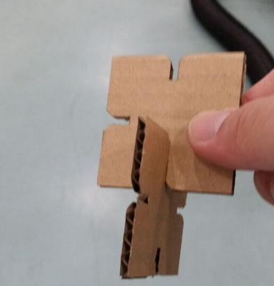
The above picture is an assembly of 2 pieces of square shape with the chamfered slots in 3mm cogurated cardboard.
 |
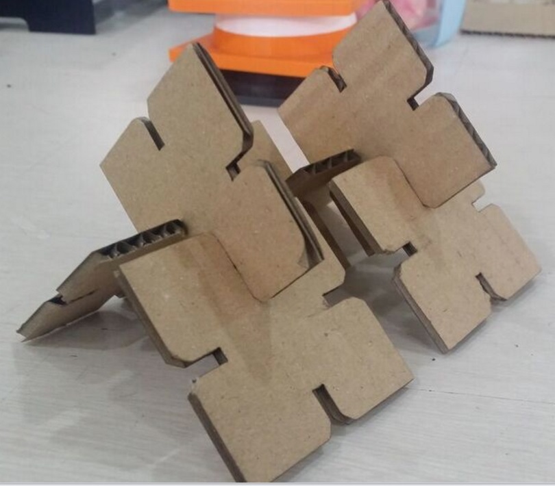 |
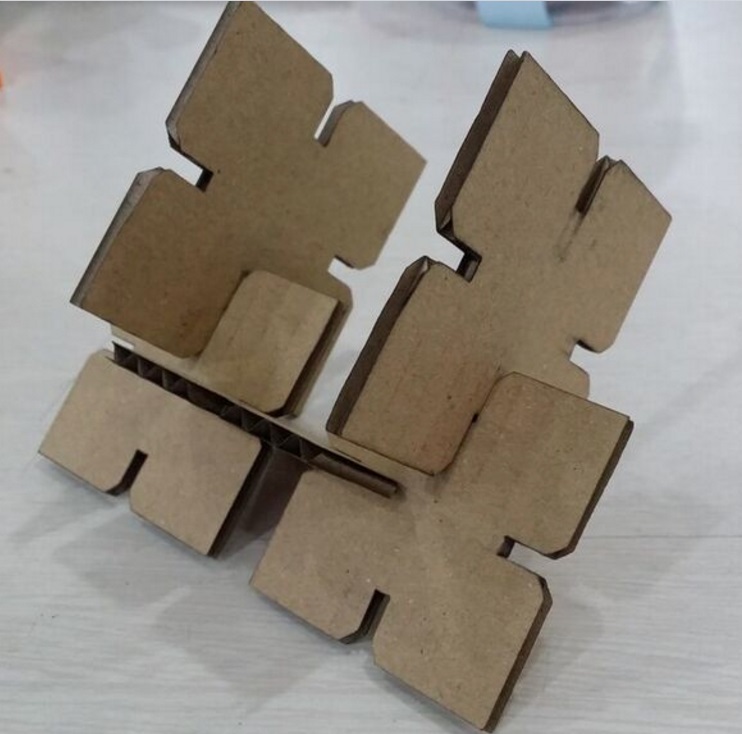
The above are pictures of the prest fit construction kit for a iphone holder
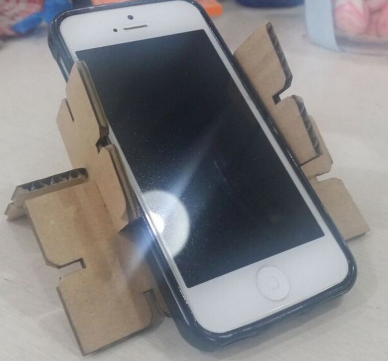
iphone is well rested on the press fit kit made with chamfered slotted 3mm cogurated cardboard pieces, but not the human.
Source files Download
vinyl cutter ready data file can be downloaded here
The press fit kit laser cutter ready data file can be downloaded here
The alternate press fit kit laser cutter ready data file can be downloaded here
references
http://fabacademy.org/archives/2015/doc/press_fit.html
http://fabmodules.org
http://fabacademy.org/archives/2015/doc/index_english.html
http://www.microugly.com/inkscape-quickguide/#clone-objects