Exercise 02 CAD...
Intro
We are going to examine a slew of Computer Aided Design (CAD) software in this particular entry. Taxonomically speaking, CAD software can be categorized into 2D CAD software, and also 3D CAD software. In 2D CAD software, we are going to further categorise the drawing functionality to raster and vector.
We will start by first examining opensource 2D CAD software such GIMP, and Inkscape. Both of these software available to Win and NIX. Then we will examine 3D CAD software such as browser based tinkercad, and also autodesk Inventor.
One important skills to learn when operating of CAD software, is the ability to traverse the import and export of various file extensions supported by the respective CAD software.
2D CAD software
the 2D CAD software can be further classify by the functionality of raster, vector or both. In raster type of CAD software, the drawing using such 2D CAD software involves colouring the pixels in the canvas. In other words, if we magnify or enlarge a drawing done with raster 2D CAD software, the output observe from the computer screen will appear pixelated.
GIMP
I have took this opportunity to create a customized Chinese New Year(CNY) theme Fab Academy assignment with 2D CAD software by using GIMP to create a custom greetings card to be circulated among friends over digital communications. First, i created a canvas of 1280x1080 pixels, then i choose the brush tool and define the colour and the size of the brush. The following diagram describes my cartoon caricature.

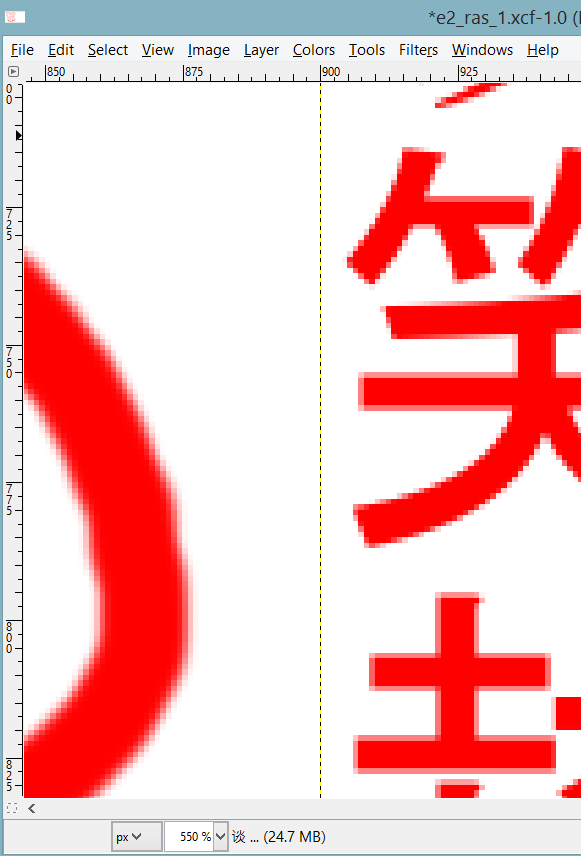
I have zoom in sufficiently to see the pixels that are coloured by the raster of 2D CAD software GIMP.
My custom made CNY greetings is available for download operational wise, the other type of raster 2D CAD software such as mypaint or m$paint operate quite similarly.
Inkscape
The next 2D CAD software used is open source and cross platform. Inkscape is very versatile, and highly recommended for 2D CAD manipulation. it supports both raster and vector. In this subsection, we are going to create a vector 2D CAD. The most obvious differentiation of vector graphic as compared to raster graphic, is the stretch-ability without loss of information. As the name suggest, the vector graphic uses a series of coordinates to represent a graphic on the canvas to be displayed on the screen. Assuming the graphic is enlarge, the collection of lines that made up of that picture do not become pixelated. In other words, vector graphic is very much suitable for graphic that requires resizing without the loss of information after a zoom in or zoom out.
Neil has mentioned the collision of traditional craft and digital fabrication technologies at an earlier address. This concept has transcended over the CNY festive season. In the following session, i will demonstrate the use of a vector graphic 2D CAD software to create traditional paper cutting art with digital fabrication.
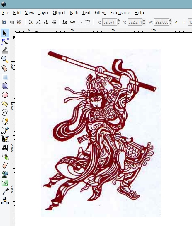
I came across this traditional chinese paper cutting art to realise a fictitious character "sun wu kong" in a very popular folk story titled journey to the west (xi you ji).

As mentioned earlier, i could hardly cut a line straight. The subject on Crafts have always been the bane in my academic career. In the following entry, i am going to demonstrate on how to create paper cutting art with the use of digital fabrication. First, we are going to use Inkscape to open the raster based image file saw earlier. The following screenshot describe the outcome.
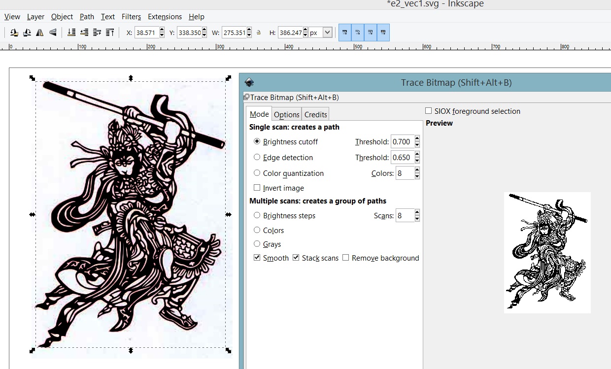
Next, select the graphic, and then choose the trace bitmap option available under Path->trace bitmap. The following screenshot describes the trace bitmap function, and the threshold to be set to obtain a visually pleasing output.
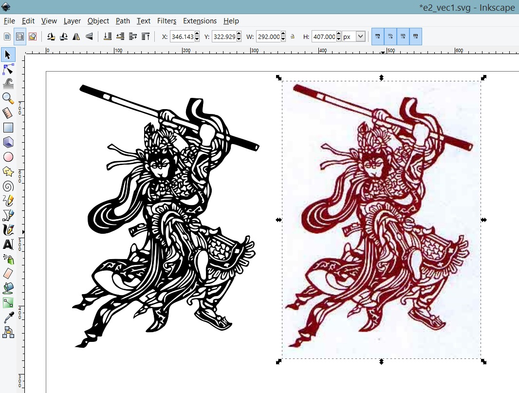
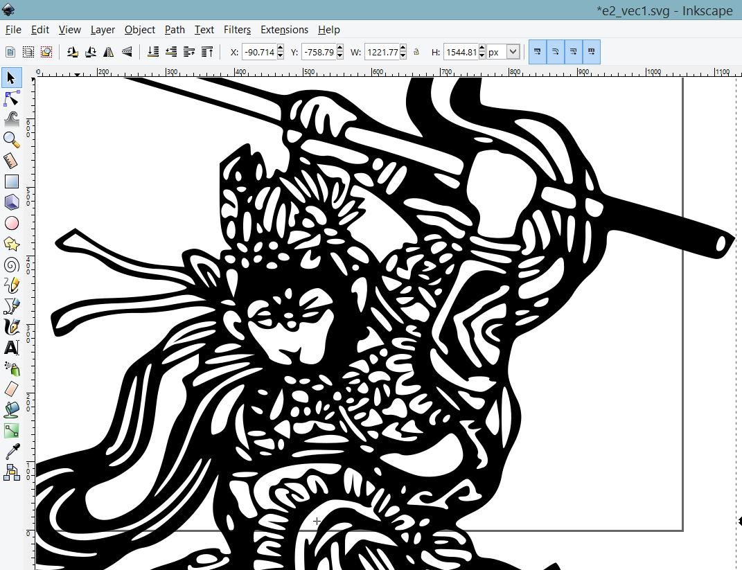
once the preferred aesthetics were chosen, the output is a vector graphic and can be observed from the following screenshot.
Assuming the newly created vector graphic is zoom in or enlarge arbitrarily, we observed the vector graphic does not lose information when it is stretched. Vector graphics are good for resizing. The following screenshot describes the zoom in.
The newly created vector graphic is available for download This data can the be used by the laser cutter to create a tangible artefact. Great artist steal, i know.
Autodesk inventor as the 2D CAD software
no doubt autodesk inventor can be used for 2D CAD. We are going to examine the workflow of autodek inventor 3D modelling that starts from a 2D sketch. details in the following sub section dedicated to it.
3D CAD software
I have not used a CAD software for the longest period of time, until i discovered the beautiful world of thingiverse. Saw a design on thingiverse that i wanted to customize to my liking, and then stumble upon tinkercad. We have campus license for autodesk products, naturally, Inventor was weapon of choice to do 3D design. In this subsection, I am documenting the tinkercad on my object of choice, and the workflow of 3D designing my final fab project using Inventor.tinkercad
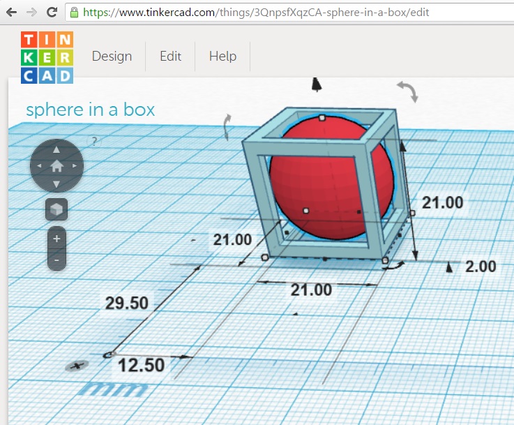
I have used tinkercad since it's inception. the only motivation to use tinkercad at that time was 1. it is browser based, all i need is a fast internet acccess. 2. it allows the import of STL file into tinkercad to be modified. Tinkercad offers a very fast methodology to customize a 3D object represented in *.stl. One interesting thing i like about tinkercad is the concept of manipulating solids in 3D.The 3D object i designed in tinkercad is the classic sphere in a box frame.
this choice of object encompassed the stark differences between digital fabrication and traditional crafts. The artisanal approach is to create a cube, and with a chisel, slowly remove the excess material to form a sphere. With digital fabrication, all it need is a 3D design exported into a data file. then this data is fed to a 3D printer.
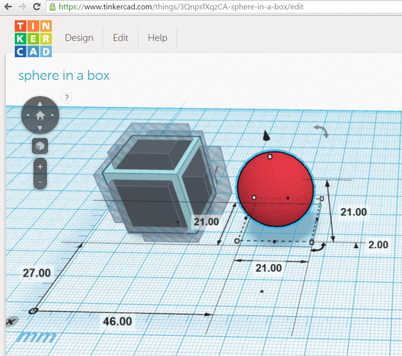
First, i drag and drop a solid cube, 3 "holes" rectangles, and a solid sphere from the toolbar of tinkercad. the i use the ruler tool and place it on the canvas. The ruler tool allows us to define the distance between the objects. The group command is a must in helping to create this sphere in the box. The hole option assserted on a solid will negate it's volume. the union of a solid object with a hole object will result in the subtraction of hole from the solid.
Manipulating solids in tinkercad is very intuitive. Just left click on the object and drag. To get the precise placement of the 3D object in 3D space using a 2D mouse, it is recommended to enter the constraints expressed in distance via the ruler tool.
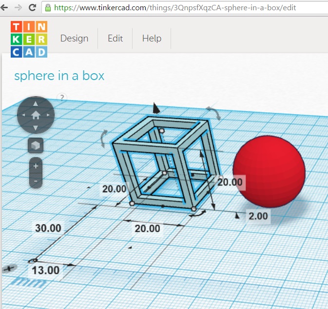
The group option was asserted on the collection of the cube and 3 rectangles that are holes. without the group option, if the sphere was moved into the hallow portion, the sphere's solid will be negated by the dimentions of the rectangles that are holes.
my tinkercad design is available viewing on tinkercad or download STL The export file formats supported by tinkercad includes *.stl, and *.obj which can be fed directly to the 3D printer's software.
check out my sphere in a box below.
sphere in a box 3D Model
The model can be rotated and zoomed with the mouse/trackpad. You can set it up with: You can set up the path to the 3D model (.stl/.obj) within this line:
viewer.setParameter('SceneUrl','res/e2_sphere_in_a_box.stl');
Result:
Autodesk Inventor
In my line of work, i was not required to use 3D cad software for 3D modelling nor i was trained systematically to use such advanced 3D CAD software. Many thanks to Mr.Roy Ang (Fab Academy 2015) for putting up his Autodesk Inventor tutorial video on youtube. Check out his channel at the reference section. The learning curve to use autodesk inventor to model my final project is still manageable.
The 3D modelling assignment with Inventor all started from my concept sketch. I have already acquired a 2D engineering sketch of my final project on a piece of paper with the dimensions meted out. From the pen and paper sketch of my final project, i then proceed to draw it in Inventor. It all started from a regular box.
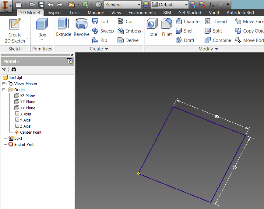
I then use the dimension tool to set constraints on the lines drawn. the following screenshot describes the 2D engineering sketch. once the sketches are done, click on complete sketch. One important take away point, the pen & paper sketch has to be as thorough as possible. When i was sketching, i did not include an opening for the 13A cables. Only after 3D modelling with Inventor, then i realised the missing component.

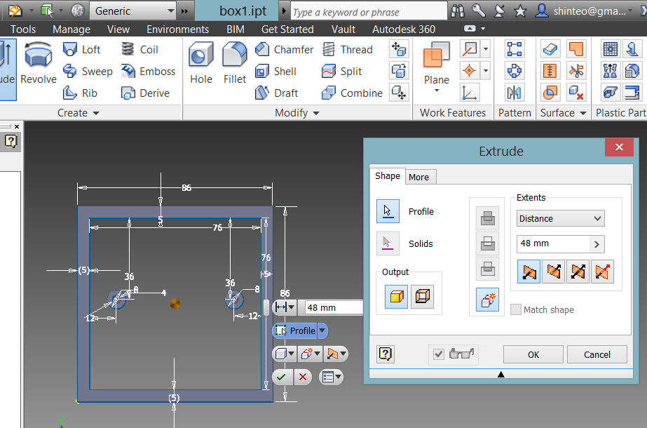
from the 2D engineering sketch, 3D model can be generated by selecting the extrude tab as per the following screenshot.
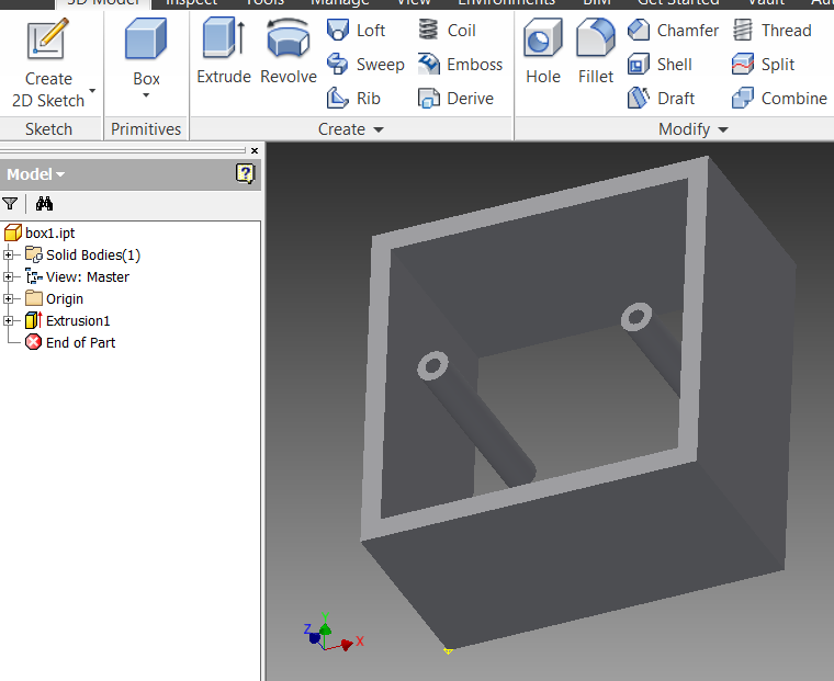
the viewing cube on the top right hand corner offers a intuitive way of viewing the 3D object modelled.
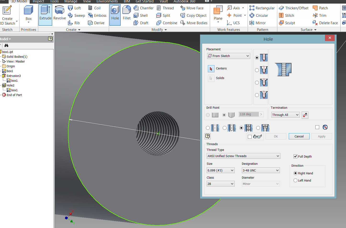
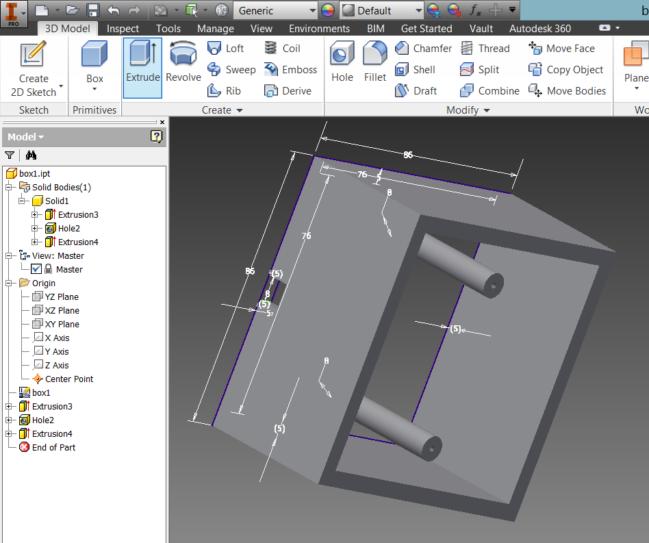
to create holes, first add the CenterPoint where the holes to be appeared in sketch mode. after clicking on the complete sketch mode, then choose the hole option from the tabs. Inventor allows the creation of M3 screw holes at the fingertip. As compared relatively to tinkercad, designing a holder with screw thread in tinkercad is going to take a significant attempt.
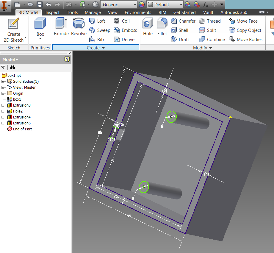
An opening for the 13A cable was missed out in the pen and paper sketch. Only upon modelling in Inventor, the missing part is obvious to the naked eye.
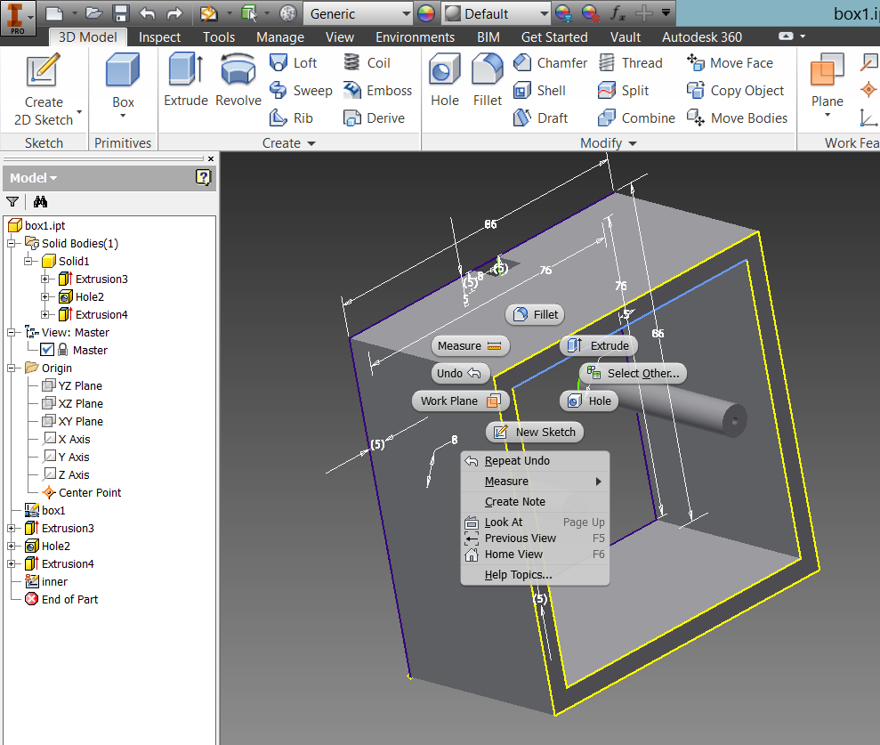
In 2D sketch of an object, it is difficult to visualize the object. In the pen and paper sketch, the drawing of a base was not captured. This was discovered in 3D design state. Hence, a base cover is then created for the 3D model.
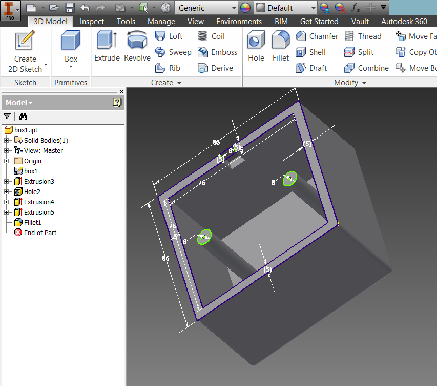
to prevent sharp edges, all 8 sides were filleted.
My 3D model of my final project in the form if Inventor part file is available for download
conclusion
engineering schematics drawing skill is a must have for 2D CAD or 3D CAD. Once the diagrams are available the workflow to digitize with the use of CAD software is quite mechanical.
There is a slew of CAD software highlighted by Neil, but time is needed to go through. I wanted to try the programmer's choice tool to design in CAD AKA Hardware Description Language (HDL)such as antimoni or openscad.
Source files Download
My custom made CNY greetings is available for download
The newly created vector graphic is available for download
my tinkercad design is available viewing on tinkercad or download STL
Inventor part file is available for download
references
inkscape tracing
Fab Academy list of CAD software
Mr.Roy Ang's Inventor tutorial on Youtube