This week's assignment
- Make Something Big
Design
This week's assignment is make something big using CNC machine. CNC is a big milling machine. We already used small milling machine for make PCB board at week 4, but this time the machine is way bigger and more powerful.
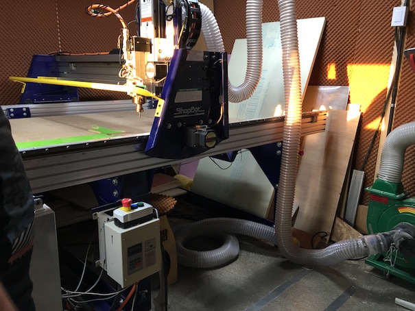 shopbot in Fab Lab Seoul
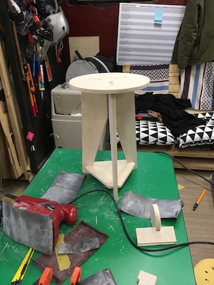
I decide to make a stool this week. It is not a 'big' compare to this project made by fablab seoul last year, but still big enough compare to my PCB boards.
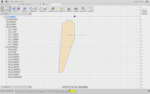
Start make a 3D model of chair by Fusion 360. Draw a leg by sketch tool.
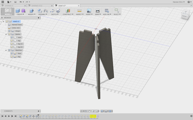
Press pull the sketch and make a pattern. Now, I have 3 legs.
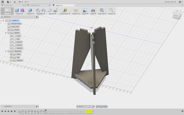
And then I add a bottom part for stable design.
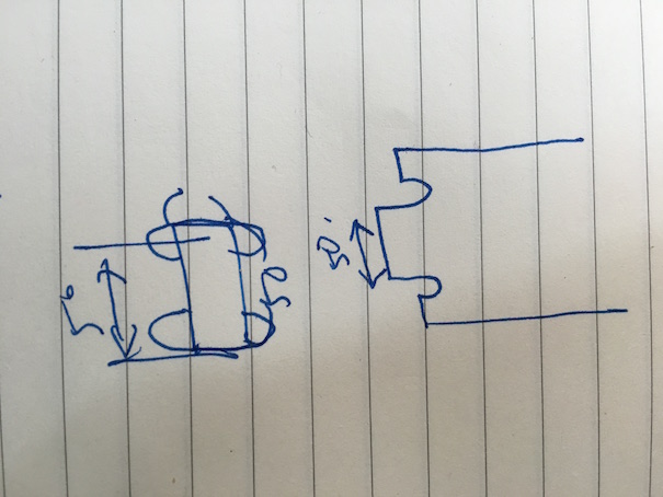
Since I did 'cut' existing design, I check the sketch again. Make sure that the outside tab and inside tab is the depth of the material I will use later.
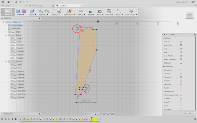 I will use the plywood which has 12.28mm of thickness
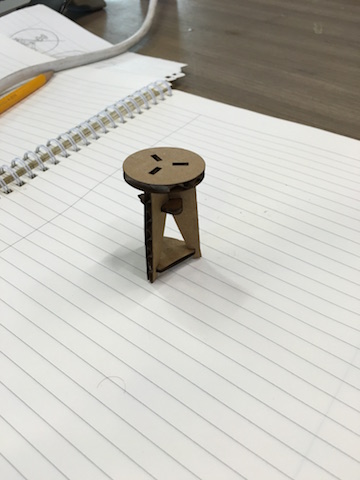
Before I tried a CNC machine I did test cut with laser cutter and cardboard. I changed my design size. Test cut is always good for design check and stability check. Also It will save the time and material. I was not sure whether my design is stable enough. But it looks pretty stable
CNC Machine
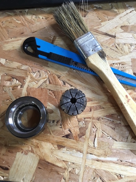
Machine Setting
Follow the steps
- Sprindle warm up; warm up the machine before using
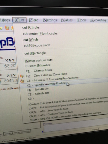
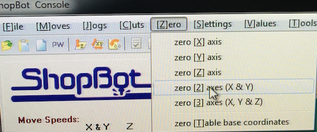
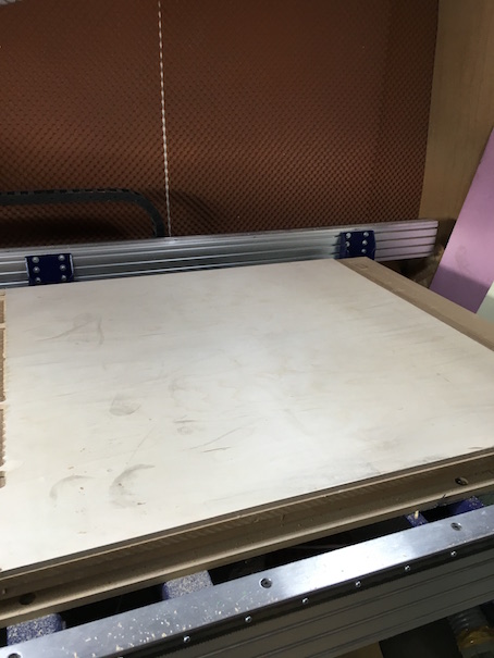
- Set the origin; this is almost same with small milling machine. Only difference is that it is way bigger. So it is easy to set the origin of z- axis and x&y -axes seperately.
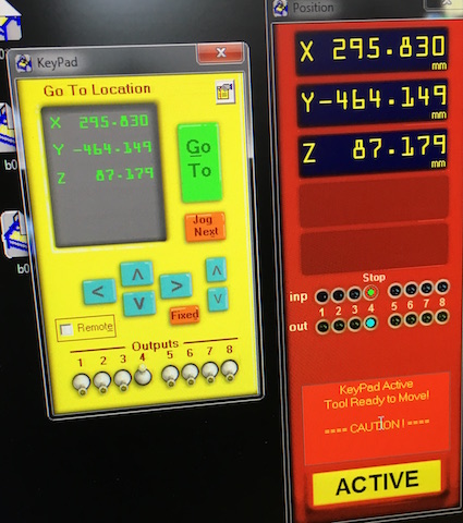
- Check the working space
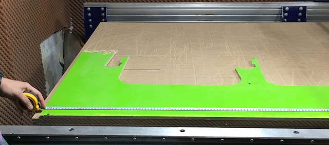
- Check the material thickness; check several points and use the average. Especially the wood has different thickness depends on points.
Joint Test 1
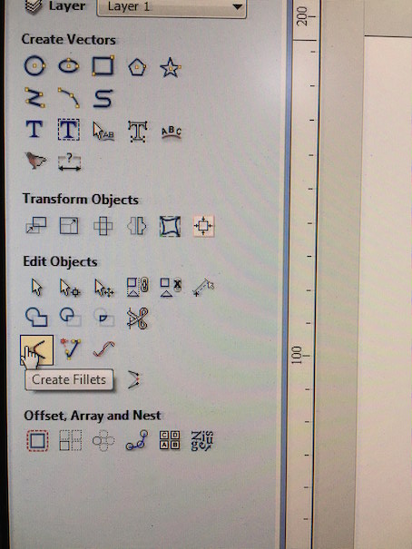
First, I tested a simple joint. The joint between seating part and legs in my design. Design tool has a 'create fillets' function which modifies the design automatically. The size of the fillet is the radius of the mill we will use.
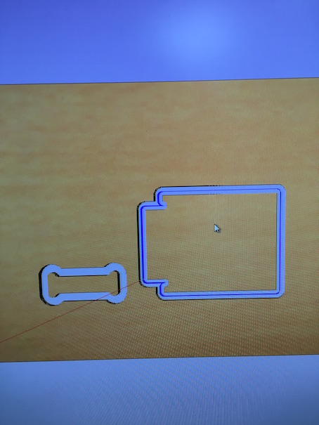
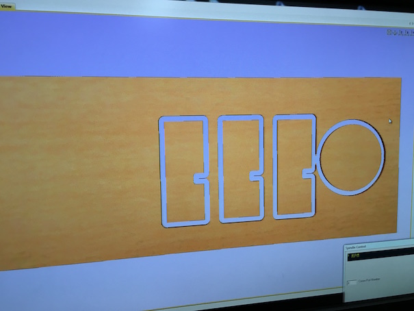
Create the tool path. In this design I only need a cut. Always check the preiview.
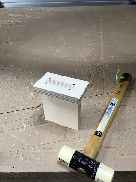 it's bit tight. I should have done tolerance test
Joint Test2
Second joint I tested is the one between the bottom part and legs. Basically it is same, so I did it without worrying about anything. And this time, I broke the mill
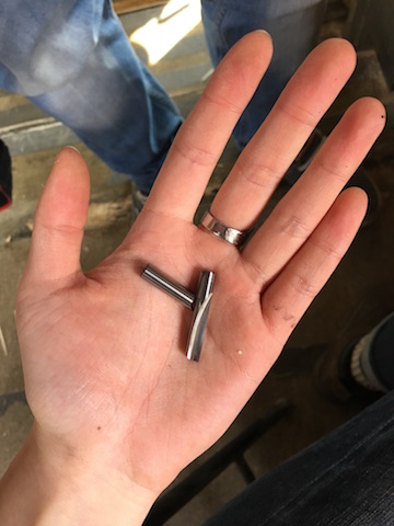 it's my 4th victim... sorry for fab lab seoul...
An instructor and I didn't know the reason. Because I checked the z origin and z zog. And it worked well till just a sec before I heard breaking sound. After we check few possible causes, we figured out.
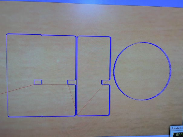
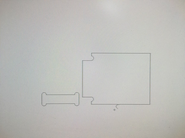
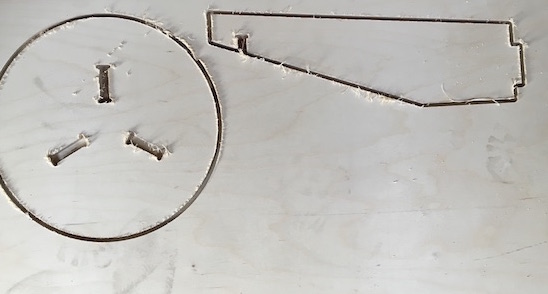
As you can see above, design was too closed that tool path is overlapped.
Because of that reason, one side of a second part is not connected to working material. We reckon that when the second part cut out, it hit the mill and broke it. Always check the tool path before cut! Give a enought space between cutout path or make a tab.
 editted tool path
The mill broke into tiny parts. So make sure that there's no broken parts inside.
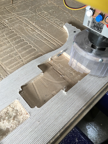
Actual Cut
Anyways, joint tests were okay. Let's do a real one!
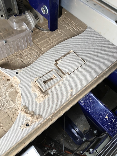
After machine finished its work, I found that it is not cut properly
In this case, we only need to cut out few more milli meters further and don't have start from the top. So check the cutting depth and change the start depth.
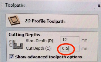
Start depth is starting point. For example, if I set the cut depth 12mm previous time and material wasn't cut properly, I could start from 12mm. Because the material had been cut till 12mm. Important thing to remember is that cut depth is not a finishing point. It is a cut depth.
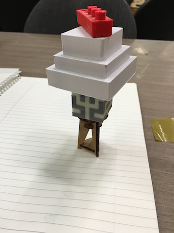
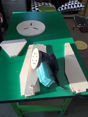
After few mistakes, I made it! Last thing was sanding for smooth surface.
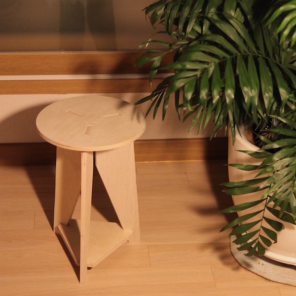
Final Result
Design Files
downloadConclusion
What I succeeded
- Joint test
- Make something relatively big
- Break another mill
What I didn't do yet
- Test the golden rule
- Make something really big
| ← week6 | electronics design | week8 | embedded programming → |
|---|