This week's assignment
- Read datasheet of ATtiny
- Programme the board to do something
Reading a microcontroller datasheet
Thanks to my back ground, I had some experience reading a datasheet. Eventhough I only read a few pages of datasheet, not like 300~400 pages. It seems so tought to read them all. Our local instructor encouraged students to read at lest till page 70. And recommended this book. I just started take a look and love to finish the book soon!
What I learned
Power & Speed
Essentials are summarised on first three pages in 'Features' section. The first thing should be checked before powering it up is that checking the operating voltage. If you use not enough power, it won't work and if you use too high voltage, it will brun or break the board.
As documented in datasheet, Attiny 44 works betweren 1.8V and 5.5V
Now we know ATtiny44 works with both 1.8V and 5.5V. Then someone might think using a lower voltage has advantages because we can save the power. But everything has pros and cons, more often said trade off. Power supply is realted to speed. So if Attiny44 is powered up by 1.8, it only works up to 4MHz. For 5.5V, speed goes up to 20MHz. So power and speed are related to each other and circuit designer should consider what features(high speed or low power consumption) are needed and which one is more important.
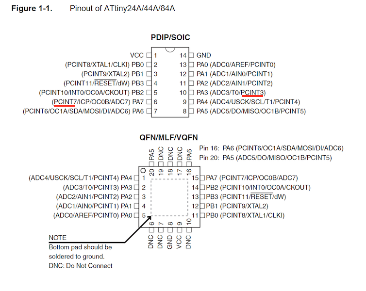
I/O
Next data we have to take a look is I/O pin of microcontroller. As it implies in its name, it controlls something by I/O pins. I'm not sure what some of their names mean(eg. XTAL, AREF, MOSI etc, etc) yet, but I can focus on basic I/O pin functions for this week's assignment. Let's check the pin number for programming later. As I made a hello-world board 2 weeks ago, LED(output) in connected pin 7 and switch(input) is connected pin 3. Do not confused between the pinout number and IC chip ports number.
Programme the board
Using Arduino IDE
To programme the board, you can do either using C or Arduino IDE. Here I'm using Arduino IDE because I'm more familiar with Arduino IDE and they have a lot of examples and easy to use libraries.
Open the Arduino IDE and button example. As we checked above, button pin is 3 and led pin is 7. Just modify the pin number in example code.
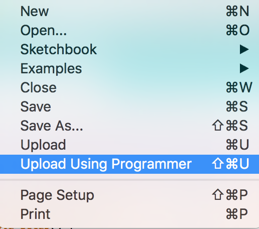
Coonect the board to Fab ISP and boatload. After bootload, upload codes using programmer.
TA - DA!
Codes File
downloadConclusion
What I did this week
- Read datasheet
- Programme the board
| ← week7 | computer-controlled machining | week9 | group work → |
|---|