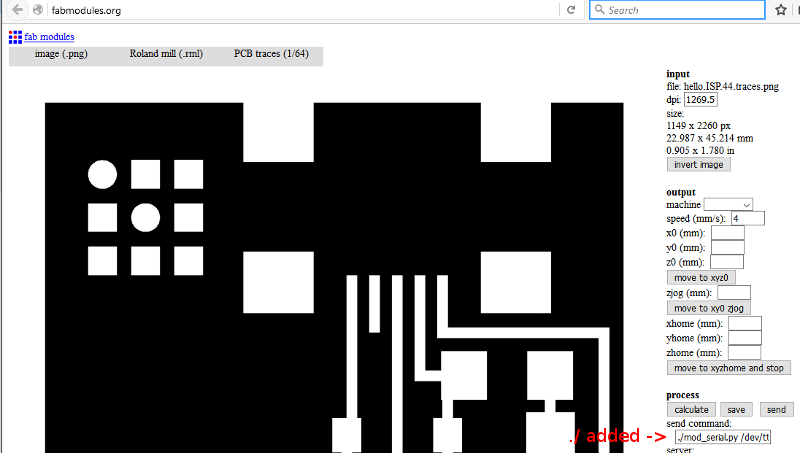
For milling I needed to fetch the Traces image and the boarder image of the ISP to load into Fabmodules. In Fabmodules I selected the Traces image as input, Roland Mill as process, and PCB Traces(1/64) as output, (1/64) standing for endmill size to use. In the dropdown under Output Machine I selected the machine we have the MX-20.
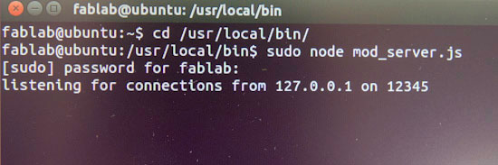
Now I had to connect to the machine, in a terminal I navigated to /usr/local/bin and the executed:
sudo node mod_sever.js
I had to add "./" to the send command window.
Now I could move the router by entering in numbers in the X and Y slots and clicking "move to xyz0", the Zero point on the mill is in the lower left corner, so to start with I entered low values around 10 in each slot and moved to xyz0. I then lowered the mill manualy by pressing and holding the down button on the router. so the workflow is something like:
- Move mill to aproximate XY position by entering those values in to fabmodules and clicking "move to xyz0
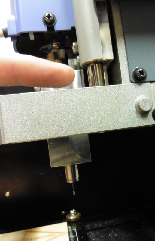
- Placeing an endmill into the spindle and pushing it as high up as it goes
- Lower the spindle on the Zaxis by clicking and holding the down button on the Mill, leaving about 1cm left so it can drill down as needed.
- Untighten the endmill in the spindle and lower the endmill itself so it rests on the copper plate, retighten mount screw. Notice there are slots for two screws on the spindle but only one should be used.
- We have now set the zero point for the Z axis, to keep on calibrating the Zero point I click "move to xy0 Zjog" this highers the spindle to a set height, in this case 2 units, but still remembers the Z zero point, now the calibration can continue.
- Click "Calculate" to have fabmodules calculate milling path and check there is no part left out.
- Click Send to start sending the router.
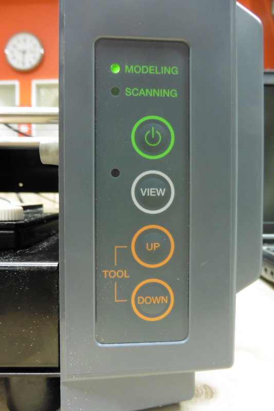
To cancel a job first press View button, then press cancel on the computerscreen, then press and hold "up" and "down" buttons simultaneously to clear out the buffer in the mill.
Soldering
Soldering went alright, I found out my that my hands are quite shaky and I placed two capacitors at the wrong place so I had to resolder them. To start with I was put off a bit in finding the right components but My fellow student Inger Le Gué made a pdf containing photos and descriptions of the parts. pdf
Programming
I followed this Tutorial to get with programming with the ISP, to start with I installed AVRdude from here. Then I ran the install file wich was straight forward. There is some issue with running this program on win8 and win10, I found a solution on avrfreaks.net forums; Thisfile needs to be downloaded and moved into utils\bin directory.
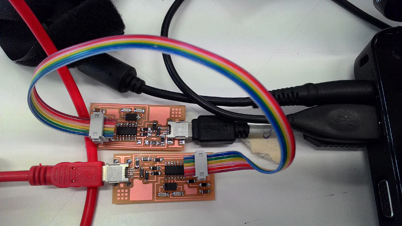
Next was to Download the Driversfor windows and The ISP firmware on a folder on my harddrive. I then connected my ISP alongside another working ISP connected together and powered via usb.
 Now to install the drivers I navigated to start menu -> Control Panel -> Device Manager, found FabISP under other devices, wich I rightclicked and selected "upgrade driver" browsed to the folder where I saved the driver and clicked OK.
Now I needed to edit the Makefile wich comes with the firmware I download and is located inthat folder. I naviged to the folder and opened the Makefile with Programmers Notepad that came with AVRdude. In the file I just needed to move a hashtag from infront of the line
AVRDUDE = avrdude -c usbtiny -p $(DEVICE)
to the line
AVRDUDE = avrdude -c avrisp2 -P usb -p $(DEVICE)
 Now I with everything connected I Opened Command prompt and Navigated to the folder where I saved the firmware and then ran the AVRdude's Makecommands:
Make clean
Make hex
Make fuse
Make program
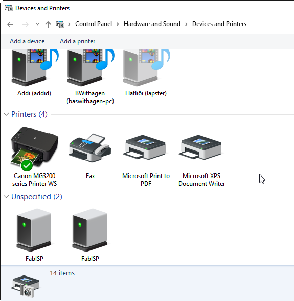
The ISP showed up in Hardware and sound in controlpanel so I deemed it working.
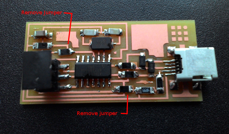
Now I could remove the 0.0 jumper resistors from the ISP.