Stepper Motor
I did not refer to the datasheet in this week as I either used code provided, or looked at the microchips pin mapping image for Arduino.
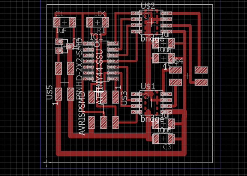
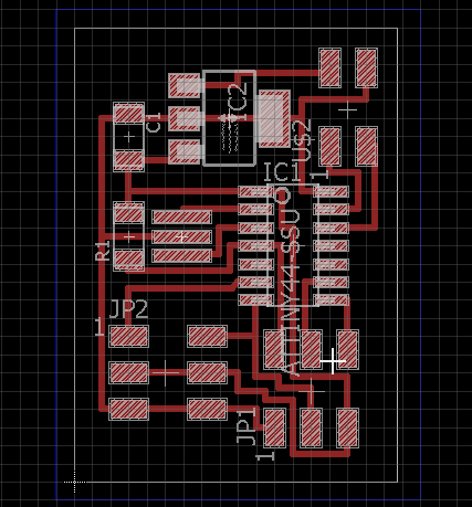
This week I was to make and design board an board with an output module. I choose the control board for stepper motors, the bipolar one, this could come to aid when wanting to control a pitch of a soundpipe if I would do an organ for my final project. I redrew the board in Eagle and picked up a few tricks along the way, like drawing a rectangle with the Polygon tool and then hitting rats-nest, this makes a path that I can route through and I could use as ground/heatsink for the A4953 chips.
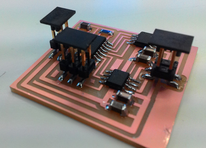
 milling and soldering went fine, once I figured that the IC2 5V component was a regulator not a transistor. I then programed the board through my isp with the example code.
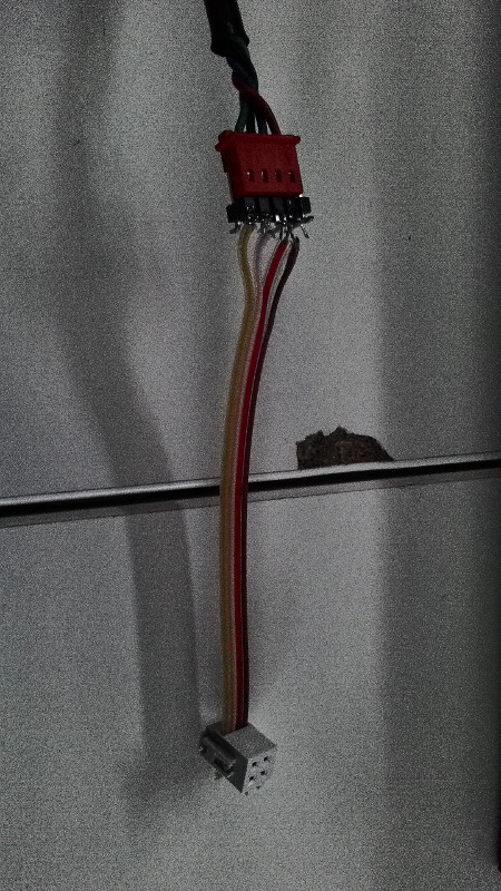
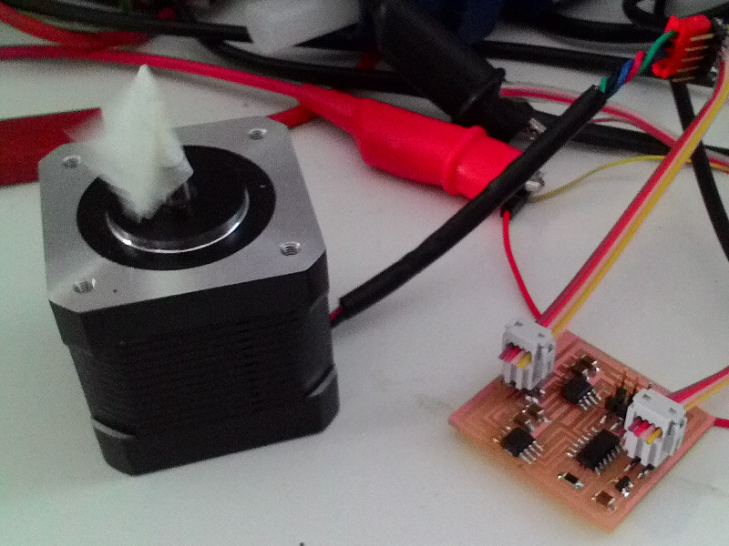
 I measured the connections on the steppermotor seeing wich two wired connected together through each motors magnet. that was the plus and minus for each one. I then made a wire that connected with 4 pins on each end, using having pins on one end that would fit in the plug of the stepper motor.
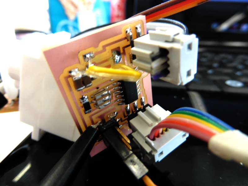
 I connected the board to a powersource. to my disapointment the board did now work, I outsourced the debbuging of the board to Bas the figured that the powersouce was set to 5V instead of 12V. With the board hooked up, I got the motors to respond to the example code. thats as far as I went this week.
Servo Motor
I returned to this week when I got around to my finalproject and changed over to a Servo Motor board I could network. I based the design of the servoboard in the fablab repository and then added a pin header for networking, connected to two avr pins for rx, tx, and then VCC and ground on the other pins.
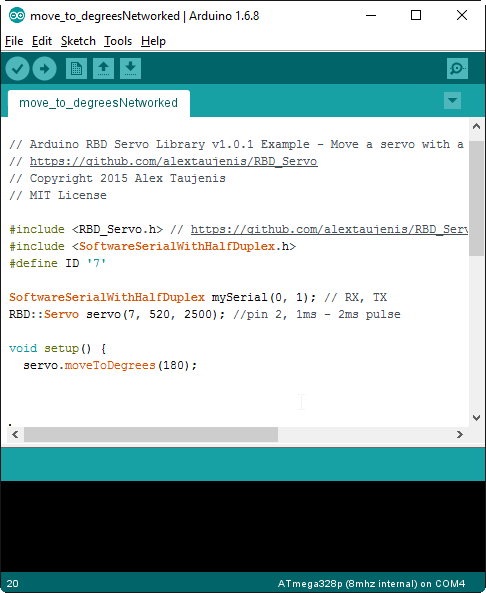
 Routing out the board and soldering went fine so next up was programming. In the Arduino IDE I added a custom library by navigating to the Filemenu -> include library -> manage libraries and choosing RBD Servo. now I could open up the Example sketch from this library and edit it ot my needs. I basicly only needed to set the higher and lower limits for the PulseWidthModulation that fit the Servo I was using, this case the range was 520-2500. And then changing the pin nr to pin7. Below is a picture of the code with some networking included:
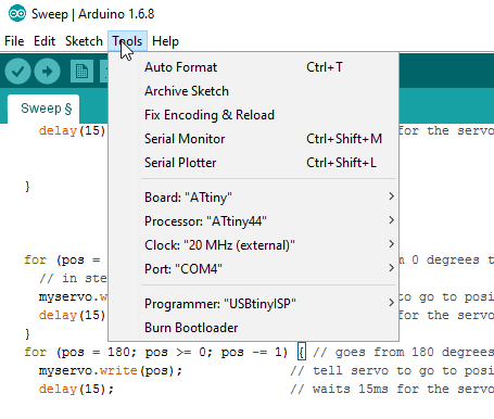
The board did not work as exepted and Bas helped my troubleshoot it with the Oscillator, when I measured the output pin I saw that the timing was off and we realized that I had chosen the wrong component for 20mhz the external clock, I had chosen an 8mhz clock, So I had to set the Bootloader to match an 8mhz external clock as opposed to the settings in the image abobe. The Voltage regulator didnt work as it should, I dont know why but it got very hot. Aparantly I had mapped the pins on it the wrong way round. so I removed the Voltage regulator and soldered an jumperwire from the VCC onward to its destination, now I would 5V to drive the motor.