Edward Octavio Muñoz Sandoval Contact: edw_ard0@hotmail.com
Week 16 Assignment: Interface and Application Programming
1.-Write an application that interfaces with an input &/or output device
Interface
For this assignment I used NI LabView software.
Labview is a very complete software if you want to communicate and visualize external devices and signals.
Have a block programming system, so it's a very visual software in the code and in the user interface.
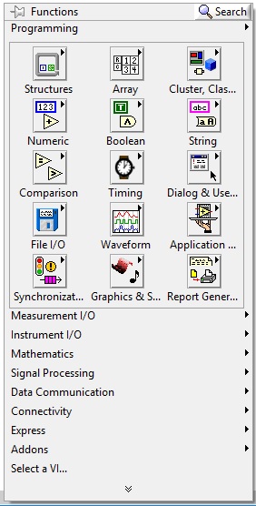
In this software you have two windows, the user interface (front panel) and the block diagram, each one have tools that can be added to the interface or the code
Front panel
Block diagram
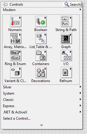
Each element in the front panel correspond to one element in the block diagram
In the block diagram, the way to develop code is adding blocks and connecting between them. You have to be careful what to connect because there are different kind of data (string, numerical, integer, etc.) and the connection have to be between data of the same type. Notice that the same block can have in and/or out of different tye of data.
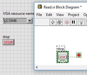
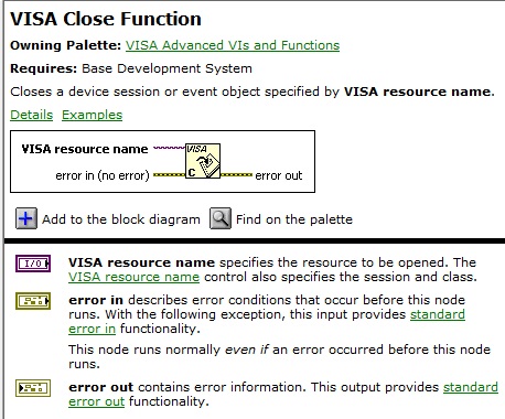
In my block diagram I used the library VISA serial of LabView, to communicate with the arduino one.
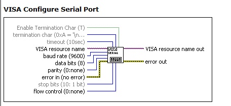
This block initialize the serial port with constant parameters set by the programmer or with variables set by the user while the program is running
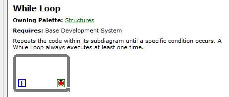
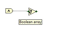
Notice that in my block diagram some blocks are in and some out of the while loop
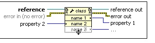
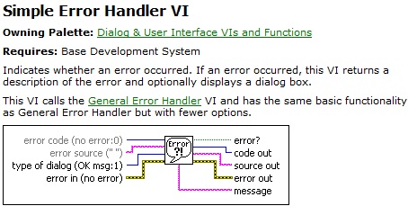
Gets (reads) and/or sets (writes) properties of a reference, in this case was not to necessary because only have i path for the information.
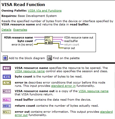
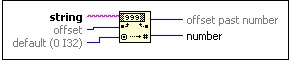
This block take string data and convert ti to number data so the "tank" block can read it
My final block diagram looks like the image:

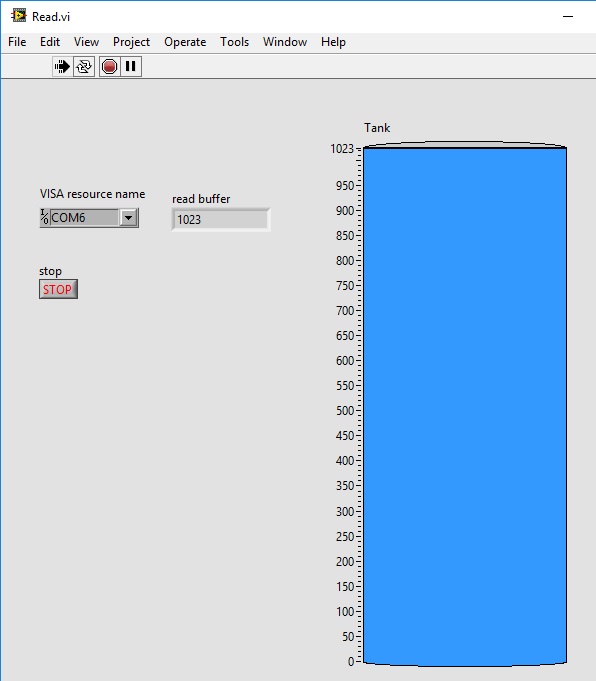
My front panel is shown in the image:
Arduino code
The code of the Arduino one is read the value from the potentiometer and send it though serial communication to the LabView code.
const int pot = A0; // Analog input pin that the potentiometer is attached to
int sensorValue = 0; // value read from the pot
int outputValue = 0; // value output to the PWM (analog out)
void setup() {
// initialize serial communications at 9600 bps:
Serial.begin(9600);
}
void loop() {
// read the analog in value:
sensorValue = analogRead(pot);
// map it to the range of the analog out:
Serial.print(sensorValue);
delay(100);
}
This is a video that shows the system working =)
Attiny code
As an alternative for this assignment, I communicate my attiny board with labview. The attiny code do the same as the arduino, read the value from the potentiometer and send it though serial communication to LabView software.
#include <SoftwareSerial.h>
SoftwareSerial mySerial(5, 8); // RX, TX
int sensorPin = A0; // select the input pin for the potentiometer
int sensorValue = 0; // variable to store the value coming from the sensor
void setup() {
mySerial.begin(9600);
}
void loop() {
// read the value from the sensor:
sensorValue = analogRead(sensorPin);
mySerial.println(sensorValue);
delay(200);
}
Also I had to use a USB-SERIAL converter to communicate the attiny and the computer.
As I rotate the potentiometer, change the value displayed on the labview screen as shown in the video: