Edward Octavio Muñoz Sandoval Contact: edw_ard0@hotmail.com
Week 13 Assignment: Output Devices
1.- Add an output device to a microcontroller board you've designed and
program it to do something
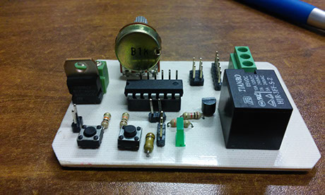
Electronic board used for this assigment:

Code
I already experimented with a led as an output in the week 8 assignment, so I wanted to test the relay with a light bulb connected to 127 VAC
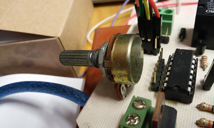
The potentiometer and the relay was already in my attiny circuit board at the 13 and 6 pin, which is the 0 and 7 programing pin based on the image:

something interesting of this practice is combination of a transistor and a relay, lets see the transistor diagram first:
I used the BC547B transistor in the saturation zone.
A transistor amplifies the collector current Beta times the Base current (B) that in this configuration is the current going from the base to the Emitter (E).
When the base current is high enough to let pass ALL the current possible through the collector, then is working on the saturation zone and it acts like a switch
The interesting part in this component is that with a small current in the base (control signal) coming from the Attiny causes a huge current in the collector, in our case in the coil of the relay.
The diode is used to prevent the return of undesired currents.
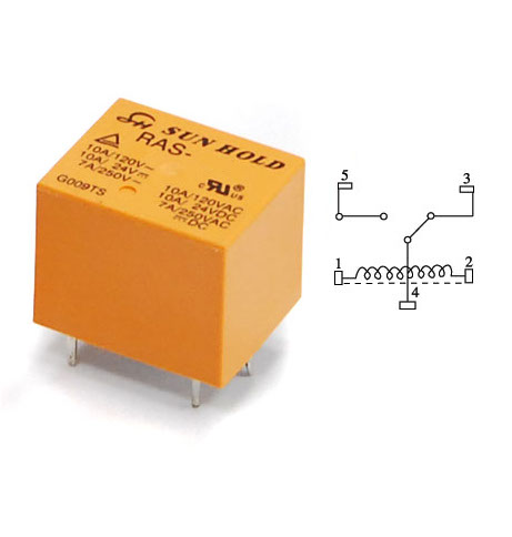
The relay works as a switch that bear elements with more power, more voltage and more current.
It have 3 terminals, The "common" terminal that is connected with the "normally closed" terminal, and the "normally open" terminal is connected with nothing. Also it have 2 coil terminals for feed it, when it is energized generates a electromagnetic field that mechanically moves a metal sheet and change the connections, in this state (activate) the common terminal is connected with the "normally open" terminal and the "normally closed" terminal is connected to nothing.

This code turn on and off the relay, based on the lecture of a potentiometer, as we know the attiny reed a binary value from 0 to 1023, depending on the voltage reed on the pin from 0 to 5 volts. This value is taken by the attiny and transform it in a delay for the relay.

As you can see in the video, the code and the board was a totally success