
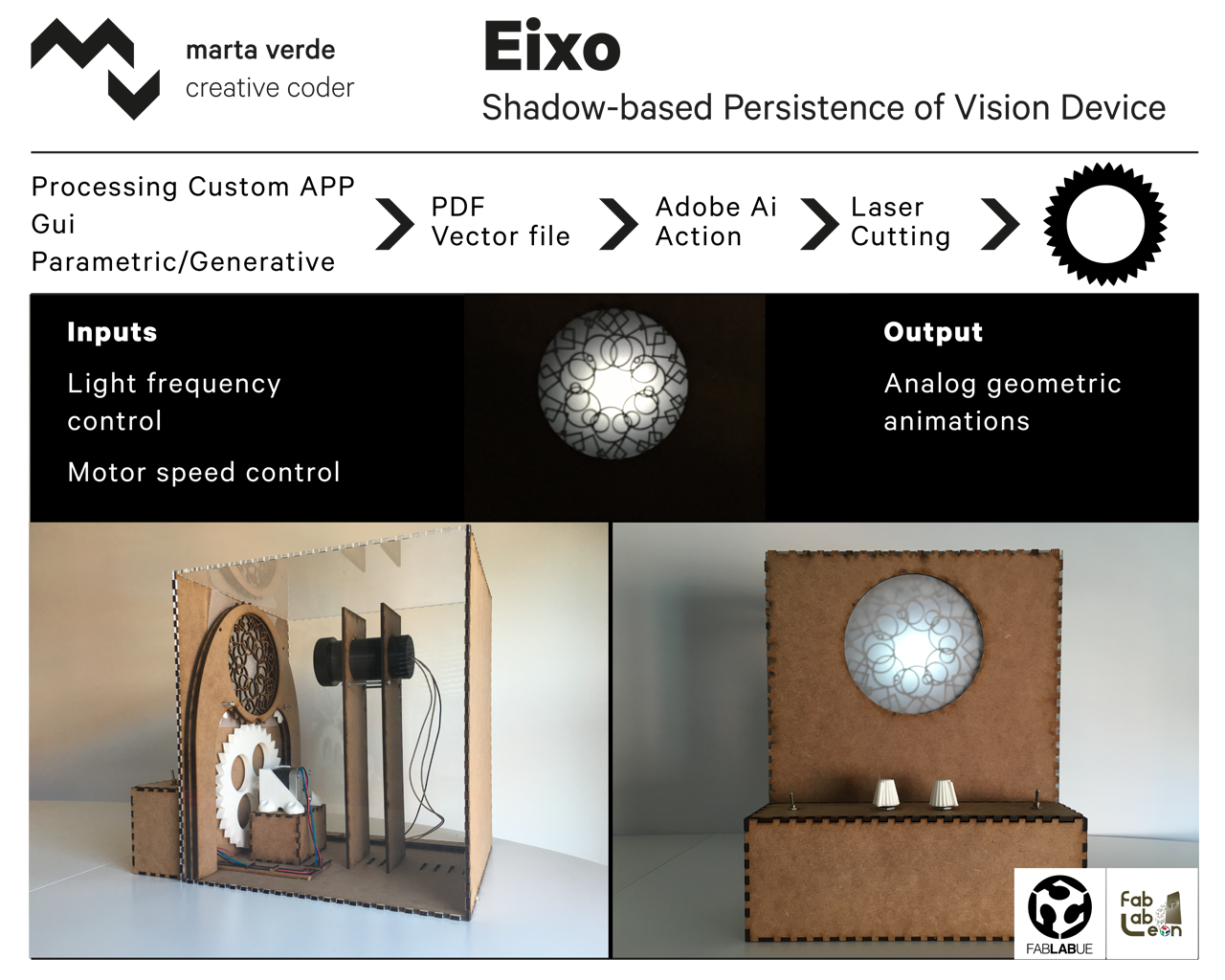
Eixo
Final project
fabAcademy final project presentation from Marta Verde on Vimeo.
Processes I used :
Star spin test from Marta Verde on Vimeo.
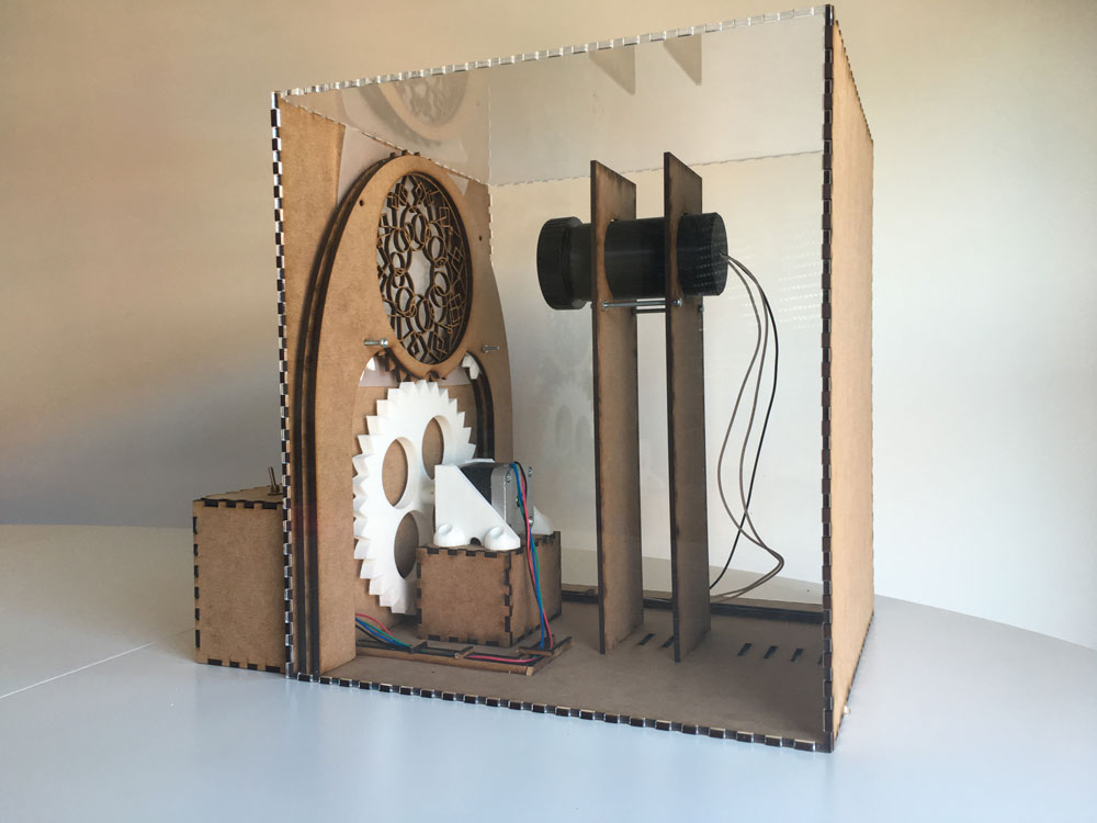
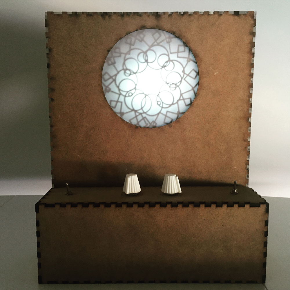
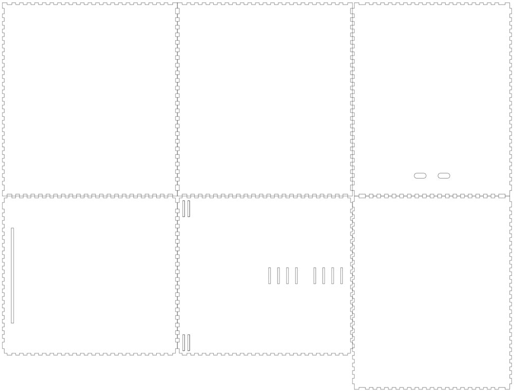
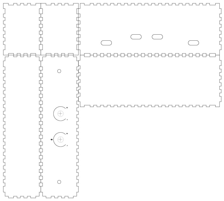
Structure
3mm laser cutted plywood & transparent methracylate:
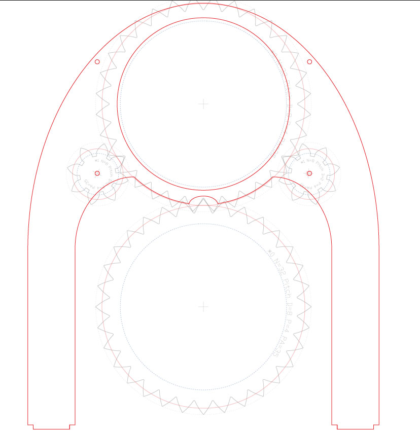
Interface Programming
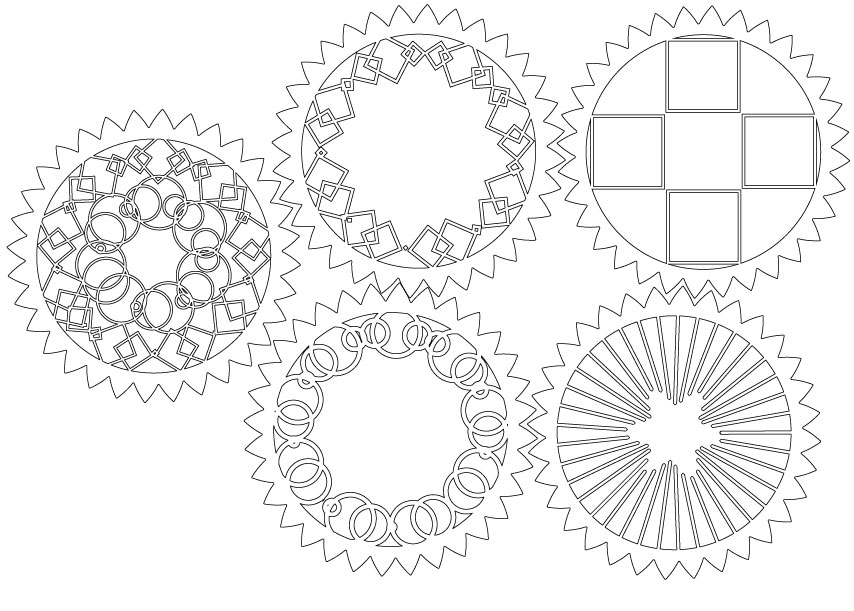
For generating the rotary items, I developed a program in Processing to be able to parametrize them, and export an vector PDF file that can be editable in any vector design software; to be laser cutted. I can also test the rotary animation with it.
p5 recursive to laser cutter from Marta Verde on Vimeo.
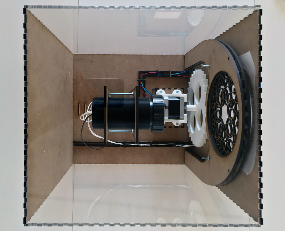
Motion system
PLA 3d printed gears, shaft and stepper motor mounting:
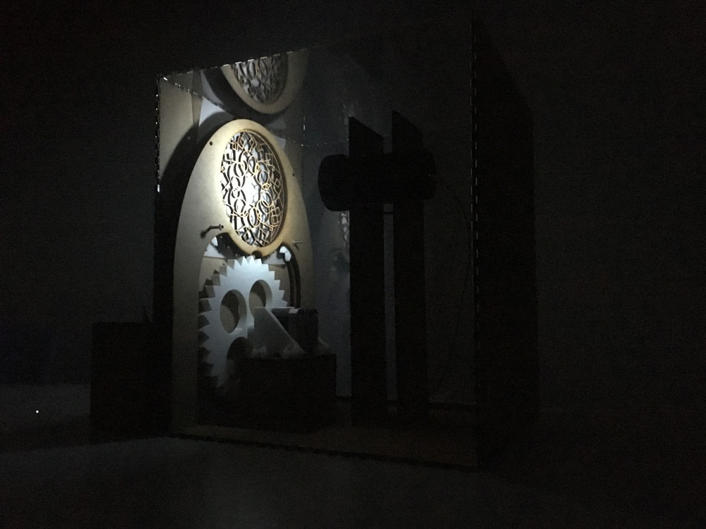
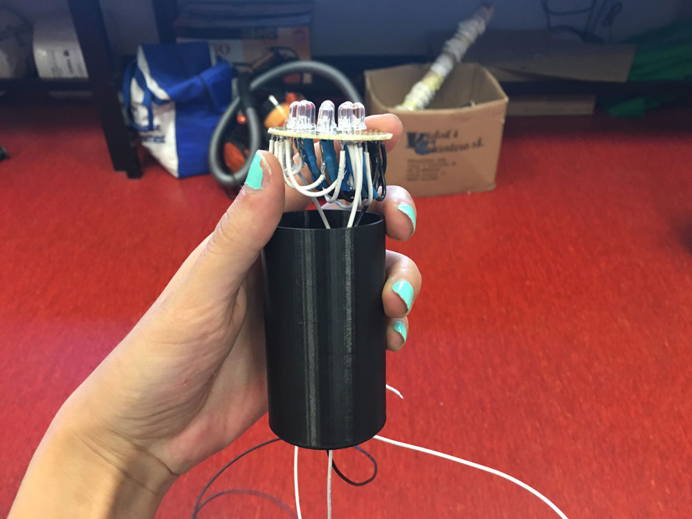
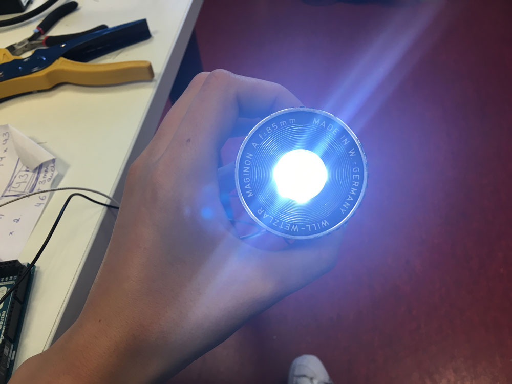
Light
DIY light source (9 Super bright & directional white LEDS) with second-hand slide-projector lens, attached to 3d Printed tube:
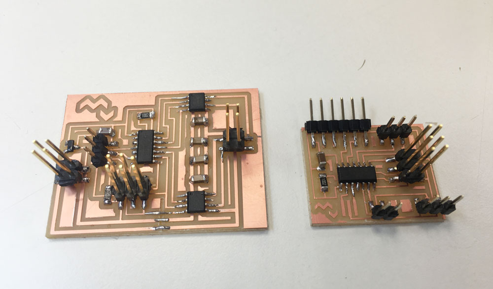
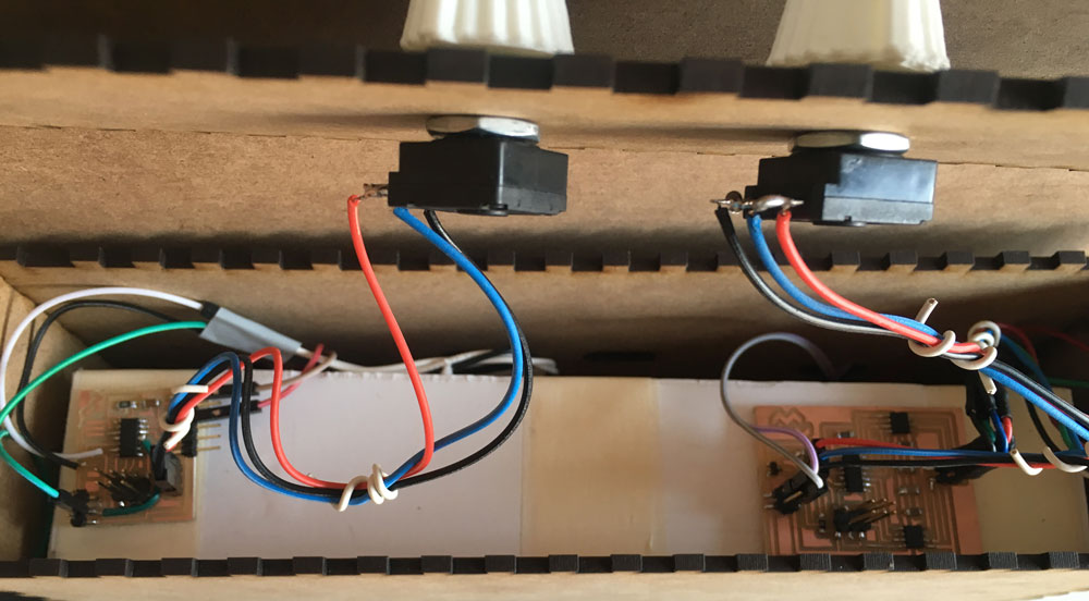
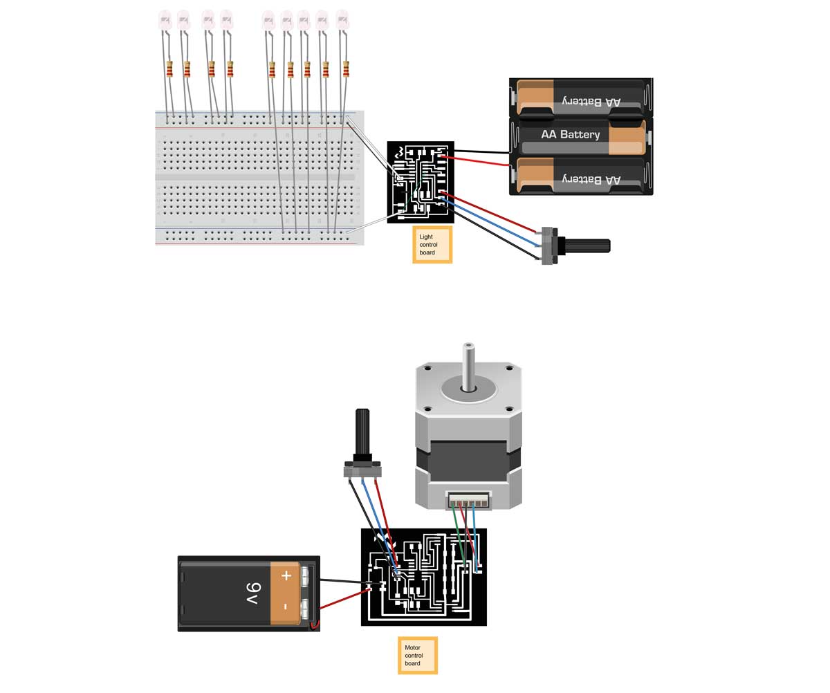
Electronics design
Because I didnt know what was going to happen with the project at the end, and I made the electronics first, I used to differenced boards, just in case of using them away or separated.
One drives the light source and the other one the motor. Each one has their own potentiometer to modulate the outputs (light frequency & motor speed and direction).
In the light one, I made a "bridge" because I was connecting the potentiometer to the wrong pin. I also had intended to use 2 of them, but at the end I used one potentiometer and "two" LED pins (4 + 5 LED), so I take advantage of the whole board witouth milling it again because I had the pins free with male headers. I feeded the motor board with a 9V battery because I didnt had access to a regulable power supply to feed it with 12V to be able to regulate the amps (I had a switching one and gave me too many amps and the H-Bridges got super hot). The light one was feeded by 3x1.5V batteries.
Light board BOM
| Part | Value | Device | Package | Description | ||
| C1 | CAP-US1206FAB | CAP-US1206FAB | C1206FAB | |||
| IC1 | ATTINY44-SSU | ATTINY44-SSU | SOIC14 | |||
| J1 | RA 6Pin SMD | M06SMD | 1X06-SMD | Header 6 | ||
| LED | M031X03_SMD_RA_MALE_POST_SMALLER | 1X03_SMD_RA_MALE_POST_SMALLER | Header 3 | |||
| LED2 | M031X03_SMD_RA_MALE_POST_SMALLER | 1X03_SMD_RA_MALE_POST_SMALLER | Header 3 | |||
| POT1 | M031X03_SMD_RA_MALE_POST_SMALLER | 1X03_SMD_RA_MALE_POST_SMALLER | Header 3 | |||
| R1 | RES-US1206FAB | R1206FAB | Resistor (US Symbol) | |||
| U$2 | RESONATOR | RESONATOR | EFOBM | |||
| U$4 | AVRISPSMD | AVRISPSMD | 2X03SMD |
Motor board BOM
| Part | Value | Device | Package | Description | |
| C1 | 1uF | CAP-UNPOLARIZEDFAB | C1206FAB | ||
| C2 | 0.1uF | CAP-UNPOLARIZEDFAB | C1206FAB | ||
| C3 | 10uF | CAP-UNPOLARIZEDFAB | C1206FAB | ||
| C4 | 0.1uF | CAP-UNPOLARIZEDFAB | C1206FAB | ||
| C5 | 10uF | CAP-UNPOLARIZEDFAB | C1206FAB | ||
| IC1 | ATTINY44-SSU | ATTINY44-SSU | SOIC14 | ||
| ISP | AVRISPSMD | AVRISPSMD | 2X03SMD | ||
| J1 | M031X03_SMD_RA_MALE_POST_SMALLER | 1X03_SMD_RA_MALE_POST_SMALLER | Header 3 | ||
| PWR-IN | PINHD-2X2-SMD | PINHD-2X2-SMD | 2X02SMD | ||
| PWR-OUT | PINHD-2X2-SMD | PINHD-2X2-SMD | 2X02SMD | ||
| R1 | 10k | RES-US1206FAB | R1206FAB | Resistor (US Symbol) | |
| R2 | 0k | RESISTOR1206 | 1206 | ||
| REG-5V | REGULATORSOT23 | SOT23 | |||
| U$5 | A4953-H-BRIDGE-MOTOR-DRIVER | A4953-H-BRIDGE-MOTOR-DRIVER | SOIC8 | ||
| U$6 | A4953-H-BRIDGE-MOTOR-DRIVER | A4953-H-BRIDGE-MOTOR-DRIVER | SOIC8 |
Electronics Programming
I coded it in Arduino IDE because I´ve using it for a long time and is fast to prototype.
Light board, to adjust the amount of flickering of "two" leds (they were 9 connected to two pins):
int ledPin1=7;
int ledPin2=2;
unsigned long timeLedChanged = millis();
unsigned long period = 1000;
boolean ledOn = true;
int strobe=100;


void setup(){
  pinMode(ledPin2, OUTPUT);
  pinMode(ledPin1, OUTPUT);

}

void loop(){
    strobe = analogRead(A3)/10;

    if (strobe >= 100){
      digitalWrite(ledPin2, LOW);
      digitalWrite(ledPin1, LOW);
    }
    else{
      strobeLight(ledPin1, ledPin2, 1, strobe);

    }

}

void strobeLight(int output1, int output2, int ontime, int offtime){

  if (millis() - timeLedChanged >= period)
  {
    ledOn = !ledOn;
    timeLedChanged = millis();
    digitalWrite(output1, ledOn);
    digitalWrite(output2, ledOn);

    if (ledOn)
    {
      period = ontime;
    }
    else
    {
      period = offtime;
    }
  }

}
Motor board, it changes the speed of the motor in two directions:
#include < Stepper.h >
int potPin = 7;
int potValue;

const int stepsPerRevolution = 200;
Stepper myStepper(stepsPerRevolution, 0, 1, 3, 4);

int stepCount = 0;
int motorSpeedLeft, motorSpeedRight;

void setup() {
}

void loop() {
  potValue = analogRead(potPin);
  motorSpeedRight = map(potValue, 512, 1023, 0, 100);
  motorSpeedLeft = map(potValue, 0, 511, 100, 0);

    if (motorSpeedRight > 0 || motorSpeedLeft > 0) {
      //clockwise
      if(potValue > 512){
           myStepper.setSpeed(motorSpeedRight);
           myStepper.step(stepsPerRevolution / 100);
      }
      //counterclockwise
     if(potValue < 511){
           myStepper.setSpeed(motorSpeedLeft);
           myStepper.step(-stepsPerRevolution / 100);
      }
    }
 }
Files

You can see all the process development of the project here.
Final costs:
Name |
Qt. |
Where |
Price x1 |
Total Price |
Nema 17 Stepper Motor |
1 |
17,30 € |
17,30 € |
|
Motor drivers |
2 |
1,42 € |
2,84 € |
|
Regulators |
1 |
0,77 € |
0,77 € |
|
Attiny44 Microcontrollers |
2 |
1,30 € |
2,60 € |
|
10k Potentiometers |
2 |
1,32 € |
2,64 € |
|
Consumables (wire, soldering iron, heat shrink, resistors..) |
1 |
|
10,00 € |
10,00 € |
MDF 0,3 wood |
2 |
5,10 € |
10,20 € |
|
Directional White LEDS |
9 |
0,58 € |
5,22 € |
|
0,3 mm Acrylic |
2 |
18,50 € |
37,00 € |
|
|
|
|
|
88,57 € |
Super super thanks to:
Attribution-NonCommercial-ShareAlike CC BY-NC-SA
