
assignment 11
input devices
This wek, we were introduced into input devices and sensors. Our duty is to mill and program an input device and measure it.
Because my final project pretends to have potentiometers for controlling the motors, I decided to build my own Hello Potentiometer board.
Hello potentiometer
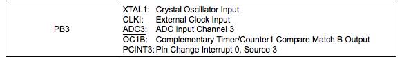
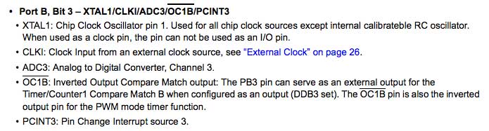
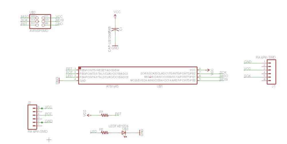
I realized that the example boards were all programmed with the Attiny45. I studied the structure from Neil´s examples and built the schematic in Eagle. I connected the potentiometer´s pin to PB3, because it works as an Analog Input (Analog to Digital Converter) as I could read on the datasheet:
1x Attiny45
2x 10k Resistors
1x 1uf Capacitor
1x LED
1x 10k Potentiometer
1x 3x2 Male header
1x 6x1 Male header
Because I was using a simple 10K potentiometer and not a smd one, I had to improve how to connect it to the board. The spacing between the potentiometer pins resulted to be double of common 2,54 headers. So I put a 6pin Header and later deleted the 3 extra pins with Photoshop.
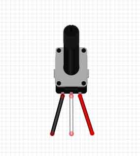
The potentiometer is connected to GND, Data, and VCC.
A potentiometer is a resistor, so I didn´t need to measure anything to connect it to the microcontroller. I also added a LED as a simple and physical output.
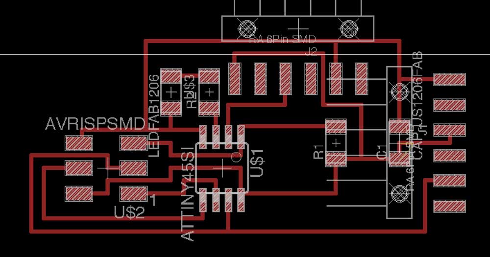
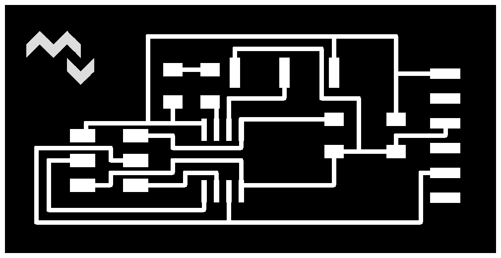
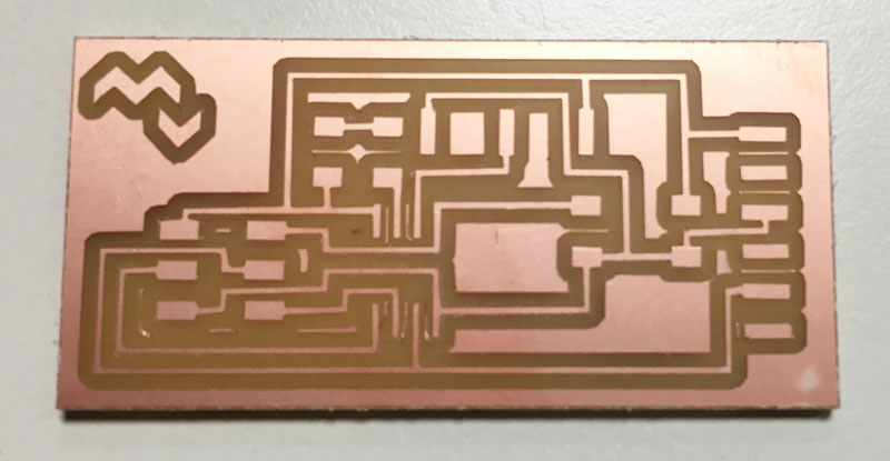
The resulting traces:
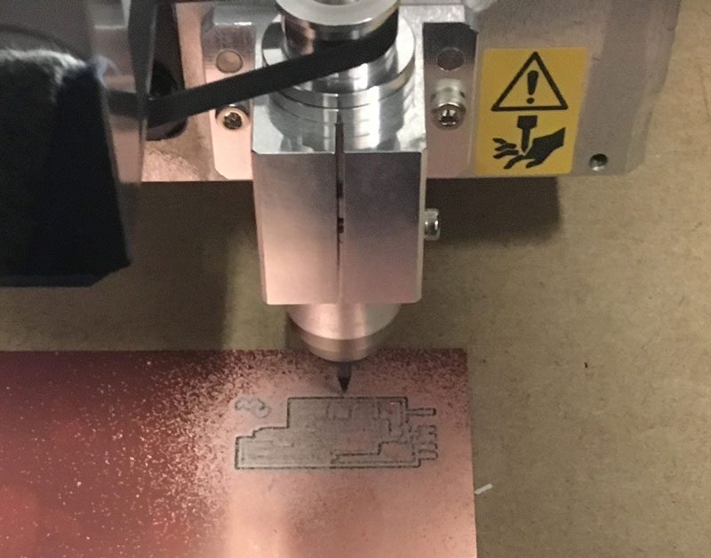
The outline cut:

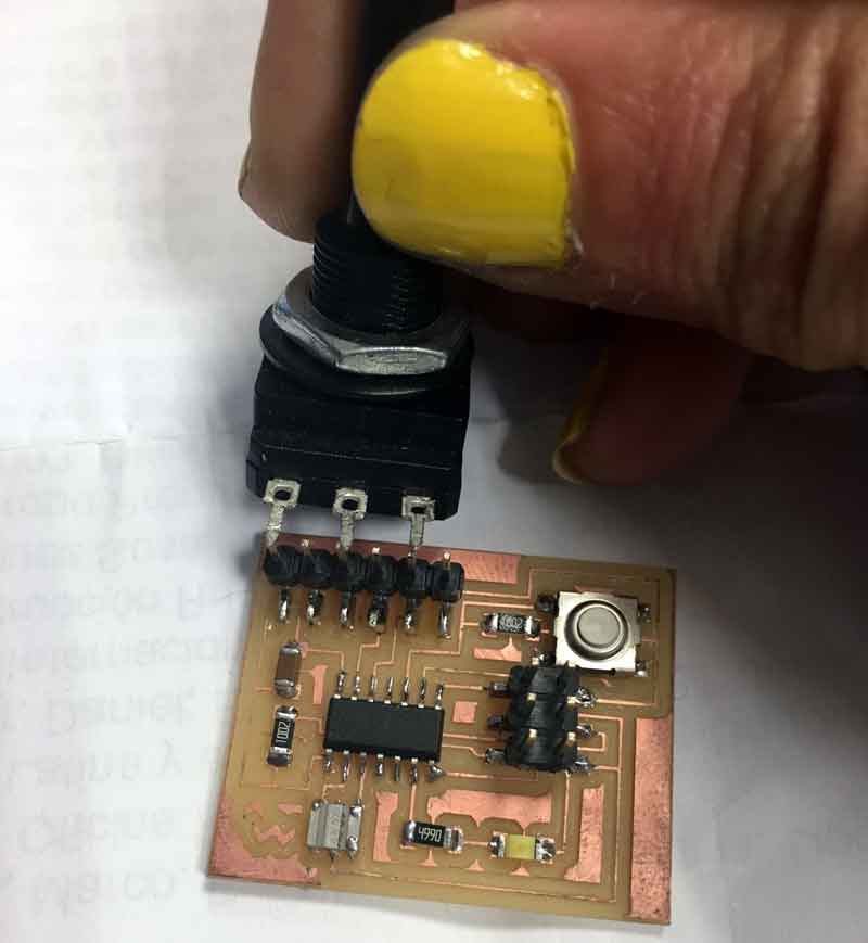
The Hello.potentiometer board, ready to program!
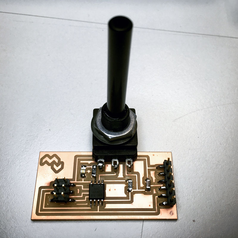
I should had thinked about where to put the potentiometer, it´s not the better position, it had to be positioned over an area of the board, not flying over it. And I have a lot of unused space on the board. Mental notes for next millings.
code
First, I coded it with Arduino, mapping the incoming potenciometer value to brightness values for the LED.
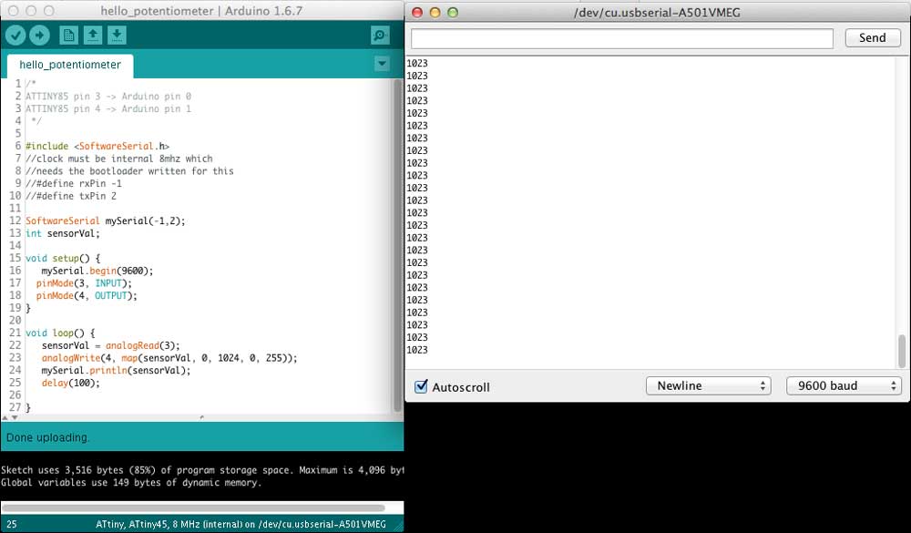
The potentiometer and the LED works, and the Serial communication too.
I made the C coding test with the hello.light.45 example from Neil. Because is an analog input, I don´t care wich sensor or item is connected to the board, they all will give me values from 0 to 1023.
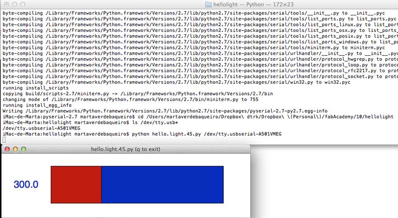
It works!!! Altough the values are not static, the reading has a little bit of jitter, but only on the float area, the output value should be an integer.
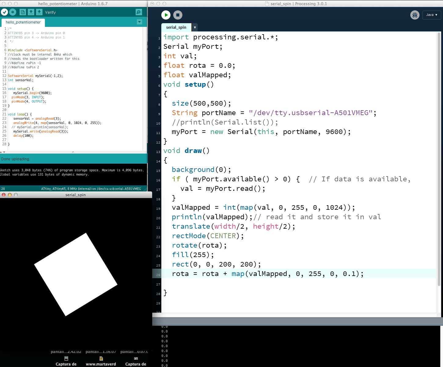
Because we didn´t get into the output devices assignment, and I wanted to see something spinning at the speed that the potentiometer gives, I tried to visualize it in Processing.
The most common way to "communicate" Arduino sketches & devices is using Firmata library. That library allows us to use the Arduino boards and similar languaje (or at least behaviours) with other softwares.
But the attiny45 seems to be not compatible or strong enough for supporting the library:
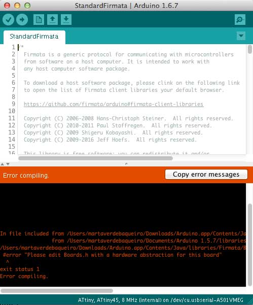
So the way was communicating them via serial in a old-school way. Processing has an included Serial library. I changed the mySerial.println() command to "mySerial.write().
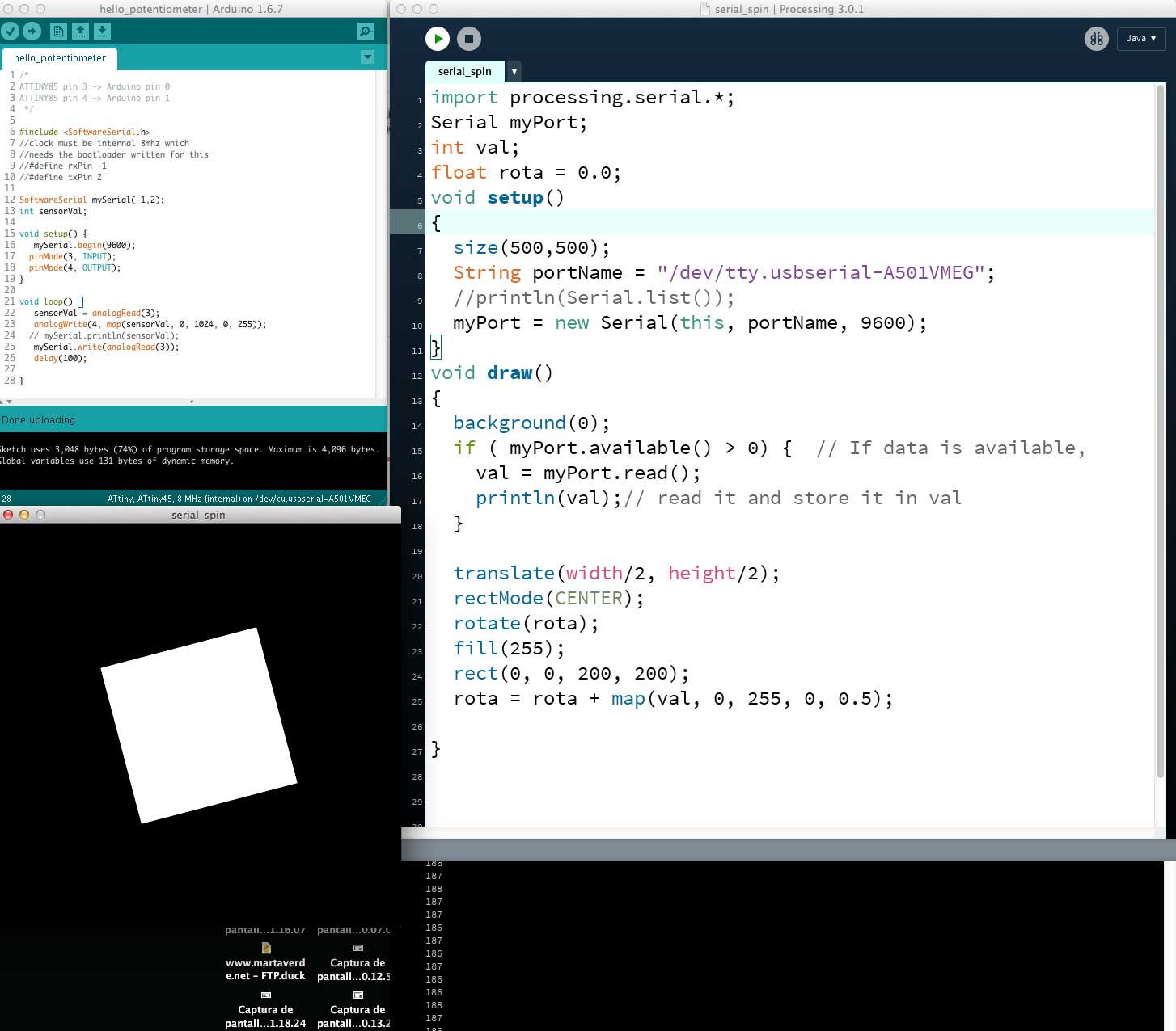
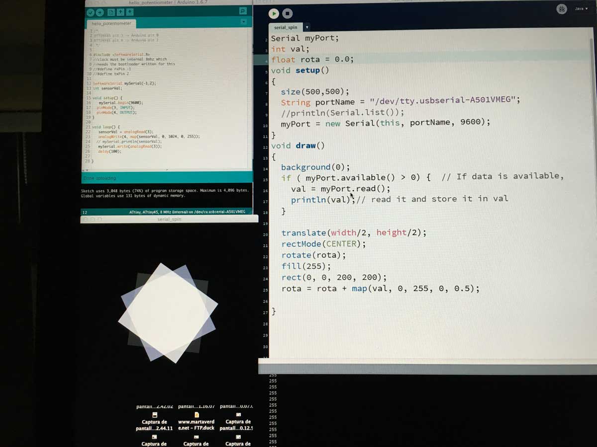
I mapped the incoming value to an increment speed for rotation. The incoming Serial value goes from 0 to 255, it should be from 0 -1023 range, so I re-mapped the values again.
*** UPDATE: I fixed the incoming Serial values in the Interface & Application Programming week, I wasnt casting correcly the incoming values.
opencv
As an extra, because Neil talked about Computer Vision, and I work a lot with that library for my work; but always on a physical way, never trhough a website, i tried some opencv-examples built for p5.js by Kyle McDonald.
But I need some extra help by some web designers. They work on local but when I upload the html with all the .js files, the camera don´t open.
I was trying it on my personal hosting, but with no luck by now. The .js files are linked, I need to figure it out yet this upcoming week.
Hello Potentiometer Traces RML file
INPUT DEVICES |
|
Described your design and fabrication process using words/images/screenshots. |
X |
Explained the programming process/es you used and how the microcontroller datasheet helped you. |
X |
Explained problems and how you fixed them |
X |
Included original design files and code |
X |