final project -- weekly assignments -- about me -- fab academy
Week 07: Microcontroller Fun
We had a lot of time for this assignment, so the plan was to do something crazy. Then, I had to do a course on work safety for working on electric cars. There was a conference to attend, too. Then, I was on a much needed short break myself. So, for now, this is just the bare minimum, more or less. I do intend to come back and do the crazy stuff, though.
The Evil Rival - Working With PICs
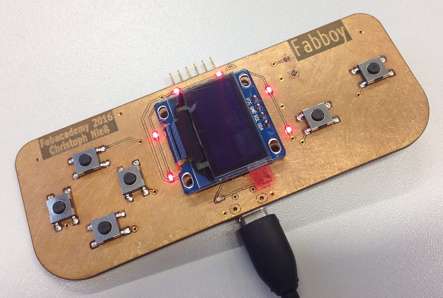
I'm working with my Fabboy-board here, which is built around a PIC18F26K22.
Each and every manufacturer has his own quirks about programming their microcontrollers. Also, each manufacturer has his own quirks about writing datasheets. Microchip is no exception, so the first step of programming (or doing anything with) a PIC is to have a look at the documentation on it. The datasheet is a good start (it even provides rough descriptions of using peripherals), and having a look at the errata can't hurt, either.
Basically, there are four toolchains you can try to use. There is, rather obviously, the current Microchip toolchain: Their XC8 compiler and the underlying MPASM assembler. Then, there is their old (and more than deprecated) C18 compiler, which is only vaguely interesting for the tons of example code out there on the net. A third option is the set of toolchains made by Mikroelektronika, which I haven't tried yet. Then, for the open source lovers, there is the SDCC project, which seems more and more interesting. As I haven't had time for experiments I'm using XC8 here and now. Giving SDCC a shot should be interesting, though. Time...
To get what I made into the PIC I'm using a PICkit 3. There are some DIY alternatives, some of which might end up a bit cheaper, but this way I do have one feature I don't want to miss: Debugging of a running microcontroller, which can save a lot of time when stuff just doesn't work.
Blinky Blink - A First Test
As a first, "hello world"-like programme the board can blink one of its LEDs (or, in my case, a whole bunch of them). Setting up the OLED-display would be a lot more work and lead to a lot more errors, so a simple blinking LED is a good start. If it works, the microcontroller is running. And if it blinks at the right frequency, the oscillator settings should be right, too.
Basic Setup
Like the fuses of the AVR world, the PICs have configuration words to do basic hardware settings. And while newer features are mostly configured in software, newer PICs still have a whole bunch of those configuration words. They are set via #pragma directives (so they are source code, not "some other information" as with AVR) and there is a (still new) tool in the IDE to generate those. You will still need the datasheet to understand what you're doing...
#pragma config PLLCFG = ON // 4X PLL Enable (Oscillator multiplied by 4)
#pragma config PRICLKEN = ON // Primary clock enable bit (Primary clock enabled)
Basic oscillator settings as generated by the tool... There is a lot more. Mostly, I don't need it at all - I won't think about stuff like code protection with an open source project, so the defaults will do for most settings.
More Setup - Runtime Stuff
As mentioned above, newer features are configured by software at run time, so they have to be done in "classic" software. For me, the oscillator settings are such a case:
OSCCONbits.IRCF = 7; // select 16 MHz
OSCTUNEbits.PLLEN = 1; // enable PLL
Getting the PIC to actually run at 64 MHz / 16 MIPS from the internal oscillator. The "microchip way" of accessing single bits in a register is different than the one used by Atmel: The headers define a struct of single bit variables, so you can just read and write them without thinking about boolean operations to get at them. While not very effective for setting large amounts of bits at once, I still like it for it's ease of use.
Blinking an LED
There are incredibly many ways to blink an LED. So, while a simple software loop would have done fine for a first sign of life, I did it the "hard way" by setting up a timer. The PIC has different kinds of them, and while one of the compare/match-timers would have been great to get exact timing for my blinking LED, I will need them for PWM at some later point and didn't want to use them now. I used Timer0 instead, the oldest peripheral the newer PICs still have.
To have something I can actually see without an oscilloscope, I had to let the LED blink incredibly slow - from the microcontroller's point of view. I wanted to do roughly 0.5 Hz, have the LED on for one second, then off for one second. Timer0 can count to either 255 (8 Bit) or 65535 (16 Bit), so I can use it to divide the clock input by either (up to) 255 or (up to) 65535. Running at 16 MIPS, there is still a lot of dividing left to do, but we do have a divider to do that - the prescaler. It can be set to powers of 2... Leaving us with a fine match at 256:
16 MHz (instruction clock) / 256 / 65535 = 0.95 Hz.
T0CONbits.T08BIT = 0; // 16 bit mode
T0CONbits.T0CS = 0; // internal clock = 16 MHz / prescaler
T0CONbits.PSA = 0; // prescaler on
T0CONbits.T0PS = 7; // prescaler set to 256 => clock input is 62.5 kHz
A few more lines are needed to set up the interrupt and the I/O-pins. The interrupt routine stays simple for now, too - It just resets the timer interrupt flag, and it toggles the LED-pin. A bit more code is needed to tell the compiler that a simple function is actually an interrupt routine, and to deal with the sad fact that the 8 Bit PICs only have one or two interrupt vectors:
// so any interrupt will end up here:
{
if(INTCONbits.TMR0IF) // Timer 0 interrupt was triggered
{
INTCONbits.TMR0IF = 0; // reset the interrupt flag
LATC ^= 0x02; // toggle LED pin
} // end of Timer 0 subroutine
}
I could have added a "preload" value to Timer0 every time the interrupt is triggered to correct its running time to exactly one second. I didn't bother, though - almost any error will lead to massive errors in running time (like the 32 kHz oscillator setting I had at some point...), so the difference just doesn't bother me for now. I will speed stuff up a bit when I continue the gaming idea, as I have plans to use Timer0 as a general system timer then.
How do you visualize a blinking LED? Videos are lame...
Of course, you can download my project files here.
final project -- weekly assignments -- about me -- fab academy
