final project -- weekly assignments -- about me -- fab academy
Week 05: Electronics Design
Phase 0: Making Tools
I'm still working on getting KiCad into my normal, everyday workflow, so one step was to work on getting more components into its library. Ferdi had suggested making a complete KiCad Fablab Inventory two weeks ago, and I was a bit reluctant - I believe any new components should be complete, including 3D models and testing. I'm quick putting in a footprint, even making schematic symbols, but the toolchain for getting 3D models into KiCad is still a massive PITA. Now, Ferdi offered to do those as he has the toolchain up and running, and Daniel offered to throw in his own footprints and symbols, so we should get that thing done a lot better than I alone could hope to. A new project was born - The Fablab Inventory KiCad Library.
Phase 1: The "Hello World" Board
I had started doing the Hello World board during Week 03 to do some additional testing with KiCad. Also, Daniel and me had a rather mad idea to do something funny and push the little ATtiny to (or, most likely, way over) its limits. That idea changed a bit when we found out that we can use other microcontrollers, too. After playing around with them, I don't particularly like AVRs, and the "imported" electronics I want to use for my final project are PIC based. So, the mad idea moved on to a different platform, leaving the schematic of the Hello World board orphaned:
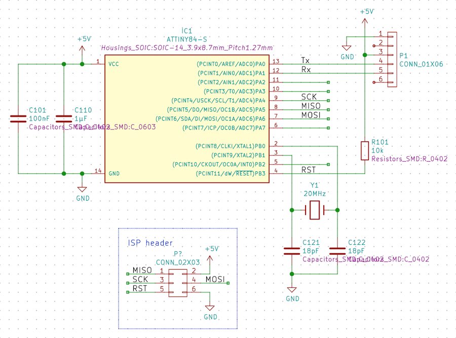
It couldn't stay that way, of course, so I completed it with the minimum the assignment said: A button (or two) and an LED (or two), and threw together a layout:
It runs Neil's demo software, so... going on to the fun part. I dropped the project files here on the way in case anyone is interested.
Phase 2: The Fabboy
The Idea
The utterly mad idea two weeks ago had been to not only add one LED to the board, but a whole lot of them - a small and cheap OLED display. And a few buttons. And software for a game, like a primitive version of Tetris. My "everyday" 8 Bit PIC is a bit faster than the original Gameboy, but only has half the memory (roughly 4 kB). That should work out for Tetris, and it should work out for Cat Invaders, both of which are available in a heap of open source projects. Porting one of those to the PIC can't be that bad, can it? (Yes, it can. But I don't care!) Embedded Programming will be another assignment...
From Zero To Schematic
Schematics don't grow from thin air, so the first step was to create one. As this project will be a rather simplistic "some stuff around a microcontroller"-project I started off by collecting what stuff I wanted to have and where it should be connected:
- The programming / debugging port. It connects to pins RB6, RB7 and reset. Nothing fancy, just a five or six pin connector. If possible, I don't want to use those pins otherwise.
- The OLED Display. It is connected via I2C, and given that I have absolutely no interest in doing that by software, it should be connected to a hardware I2C port. The PIC has two of those, with connections to RB1 / RB2 and RC3 / RC4. I'll have to choose one pair later.
- A little piezo speaker. To make programming easy, it should be connected to a PWM output, and there is such a bunch of those that I won't list all of them here.
- A cable connection to play against other users. A UART might be a good start for that. There are two on this PIC, one of which is conveniently sharing its pins with the programming / debugging port which needs a connector anyway. I'll use that if I ever get around to programming any multiplayer.
- A few LEDs for creating an ambience and annoying the player. Having them on one or more PWM pins might be nice to create effects. There are a whole bunch of those, so we'll see later.
- A bunch of buttons. The original Gameboy has eight, six of which are used in most games. As we have just enough buttons left at the lab to do six... I will do six. They can be put on any I/O pin, so not much to think about here. Only Port B has internal pullups, though, so...
The buttons were the first thing to be fixed in the end, as with six buttons and six pins-with-pullups left, they were an easy fit (and less layout work). That left one pair of pins for the I2C to the display, and a very reduced set of PWM pins, so the schematic is more or less sorted:
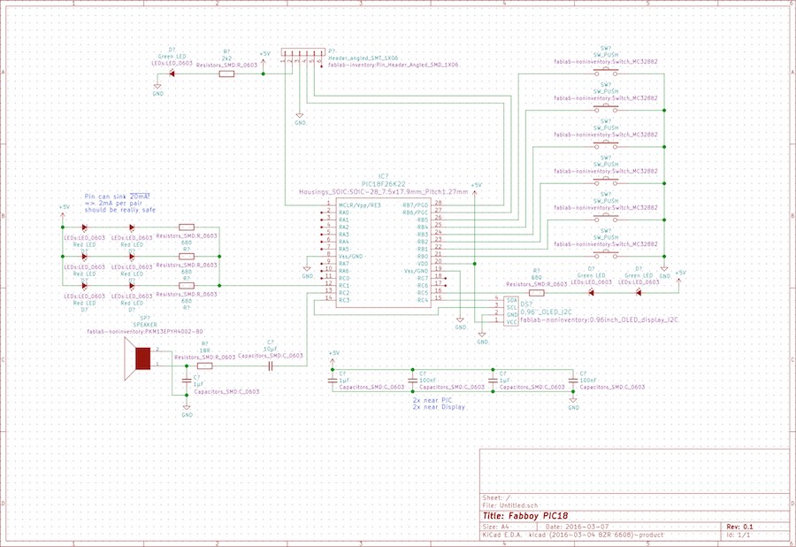
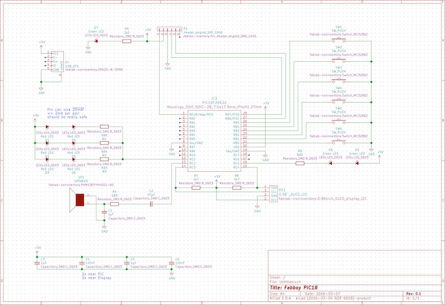
There's a power-LED already added, which might help when debugging this thing. And brings up the next problem: How do I power my toy? A battery might be cool, but adding a rechargeable one and not killing it adds to complexity and workload, I'll leave that out for now. I could plug a power cable into the debugging port, but that blocks out any other use of this port - like multiplayer. So, again, no. In the end, I added a micro USB port, not doing any USB, but just drawing the few milliamps of power I need. It's not OK with the standard, but it should work.
There is not much more to this schematic. The I2C needed its pullups, and I put some capacitors to the PIC's as well as the display's power supply. And that's it. With 5V from USB, our power supply is set and the PIC doesn't really need a crystal, so I'm leaving that out.
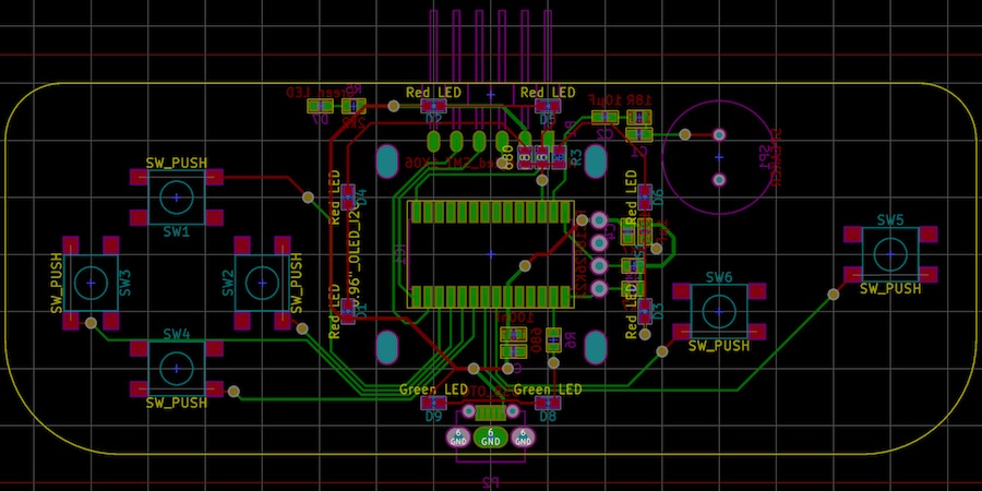
Drawing Up The Board
For a lot of simple games like Tetris, a landscape screen is a rather stupid idea, especially one as wide as the small OLEDs we have. So, I decided to put it in as a portrait display, which looks odd, but should work. Also, with a display that small the whole thing shouldn't really be big. At the same time, I really like the general layout of the original Game Boy Advance, so I shamelessly copied it (it wasn't new for Nintendo, either...).
There is a lot of documentation missing here that I will have to write up as soon as I can
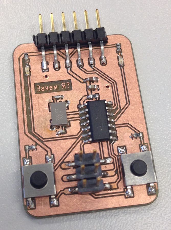
Teaser:
Making It
final project -- weekly assignments -- about me -- fab academy
