
Week 4: Build an Atmel-ISP
Hmm, an Atmel-ISP... Don´t know how many of these lay arround here, i think 4. But lets make a fifth...
I don´t want to invent the wheel again, so i looked for an ISP from the last years class and found the
"FabTiny*ISP"
It´s a nice little layout for an ISP, using a Tiny45 and double-use the reset pin. This way no jumper is needed.
Basicly it is perfect. But i found a little feature to improve it: in the original version you need a ribbon-cable to
connect the ISP to your circuit. I don´t like these cables. They are always 1cm to short, no matter how long the cable is.
The cable breaks, longer than 30cm brings problem, and debugging is a pain. So my ISP will have a female-pin-header on the short side...
This way you can put the ISP directly onto the circuit and can use a standard-usb-cable up to 5m for the connection to your PC.
Let´s go... I´ve downloaded the eagle-schematics from the FabTiny*ISP-Page and refined them a little bit.
The old design uses big 1206 resistors, the layout didn´t allowed my second pin-header,
and for debugging-reasons (or to repair a common failure while programming) the XTAL1 and XTAL2 Pins of the Tiny45
was routed to two extra-pins on the ISP-Connector. This is not bad, for the case you bricked the Tiny with a wrong oscilator-selection.
Well, i hope i don´t make this mistake and made a 6-Pin-Connector out of the 8-Pin.
The resistors were replaced by 0402-packages, the two capacitors by 0603. This way i could make the circuit-board a little bit smaller.
Ah, the USB-Connector... The old design uses the PCB as USB-Connector. It is a nice idea, but i don´t work with the most USB-Ports due to the heigt of the PCB.
So replaced this by a micro-USB-connector. Smaller and more reliable...

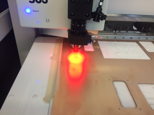
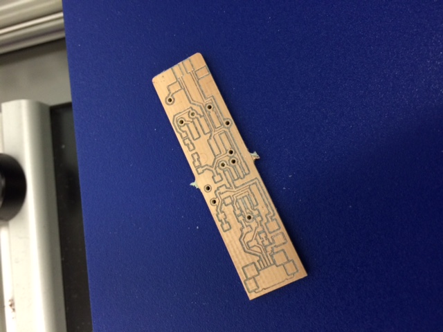
After the layout comes the building... Luckily we have a PCB-Mill in our Lab, a "S63" from LPKF. Price around 25.000$, but
it is a dream to work with it. Simple steps:
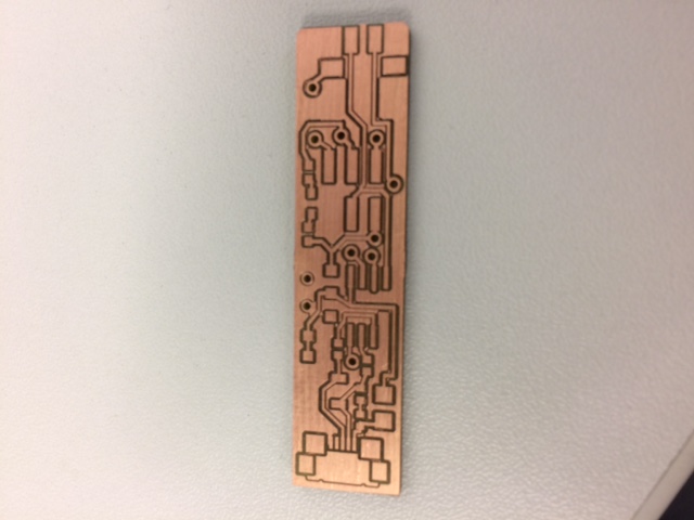
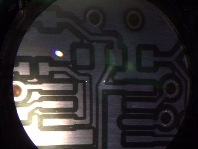
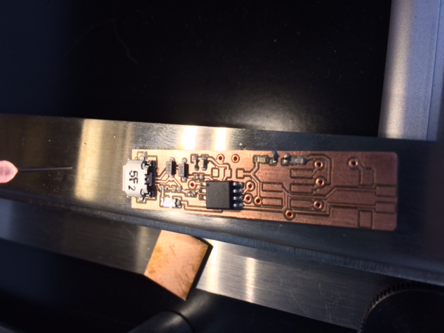
After milling it its a good idea to scrub of the PCB to remove old fingerprints and stuff. After this i applied some solder resist
and checked the board under the microscope.
To connect the vias i used a "Favorit" rivet-press from Bungard:
"Bungard"

At the next step i used another machine from LPKF, a Pick-and-Place. This
machine is basicly a X-Y-Machine with a air-actuator. You can dispense and place parts very fine-pitch.
So: first dispense solder-paste on the Board, then place the Surface-mounted-parts into the paste.
At this step i didn´t placed the switches and pin-headers. I don´t know if these plastic-things likes the heat
in the reflow-oven...
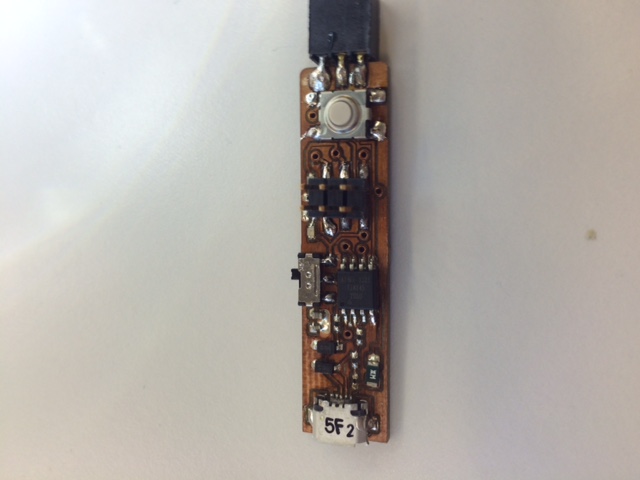
After 3 minutes at 200°C it looks fine :)
Just placing the switches and solder it by Hand, and voila, the finished "FabVeryTiny*ISP"


Last step is burn the ISP-Programm into the FabVeryTiny*ISP. I don´t document this, because i don´t think the World need more screenshots from AVRDUDE...
You need exactly the same steps like in the 2015 documentation, so please look here
If you want to build your own FabVeryTiny*ISP you can download the eagle-files here:
FabVeryTinyISP.zip