
Week 16: Building a GUI
This weeks assigenment was very interessting, because i can use it often on my work or hobby-projects:
Build a GUI to interface with your microcontroller!
A few years ago i made a GUI with LabView, very straight forward, but not a c or c++ programming. It´s more a graphical and mathematical solution.
So this time i wanted to learn something new and choosed QT.
Basicly QT is a framework written in C++ for generating and interfacing a GUI. It is Open-Source and available
for almost every system for free. You can even build iOS apps with it.
You CAN programe QT in a text-editor if you like, but i used the "QT-Creator" IDE. The IDE is also free
and very comfortable. Especialy you can drag and drop your "Widgets" (your graphics and buttons) on the place you want it to be.
This is much easier than program the coordinates of the widgets by Hand.
You can find everything you need on www.qt.io
If you generate a new project, you see on the left side five important files:
There are a lot of realy good hello-world-tutorials on the web, so i will not explain how to get started exactly with QT...
For the interface with the Fab-Pic i wanted to realise a two-way-communication by UART.
On the one hand i wanted three sliders to control the PWM-output for three LEDs, on the other hand three LCD-Displays for the first three ADC-Inputs. After experimanting with the serial-code on mac-os-x i wrote two short routines for this.
              void MainWindow::serial_connect()

      {

          serial->setPortName(ui->port_box->currentText());

          serial->setBaudRate(QSerialPort::Baud115200);

          serial->setDataBits(QSerialPort::Data8);

          serial->setParity(QSerialPort::NoParity);

          serial->setStopBits(QSerialPort::OneStop);

          serial->setFlowControl(QSerialPort::NoFlowControl);

          serial->open(QIODevice::ReadWrite);

  //        serial->write("Hello World!\n");

      }

  void MainWindow::serial_rescan()
  {
      ui->port_box->clear();
      foreach (const QSerialPortInfo &serialPortInfo, QSerialPortInfo::availablePorts())
          {
          ui->port_box->addItem(serialPortInfo.portName());
          }
  }
The serial_rescan gives you a list of all available serial-ports on your system.
The second one opens the choosen port with 115200Baud, 8-n-1 and no flow-control.
After this i started to create the GUI itself:
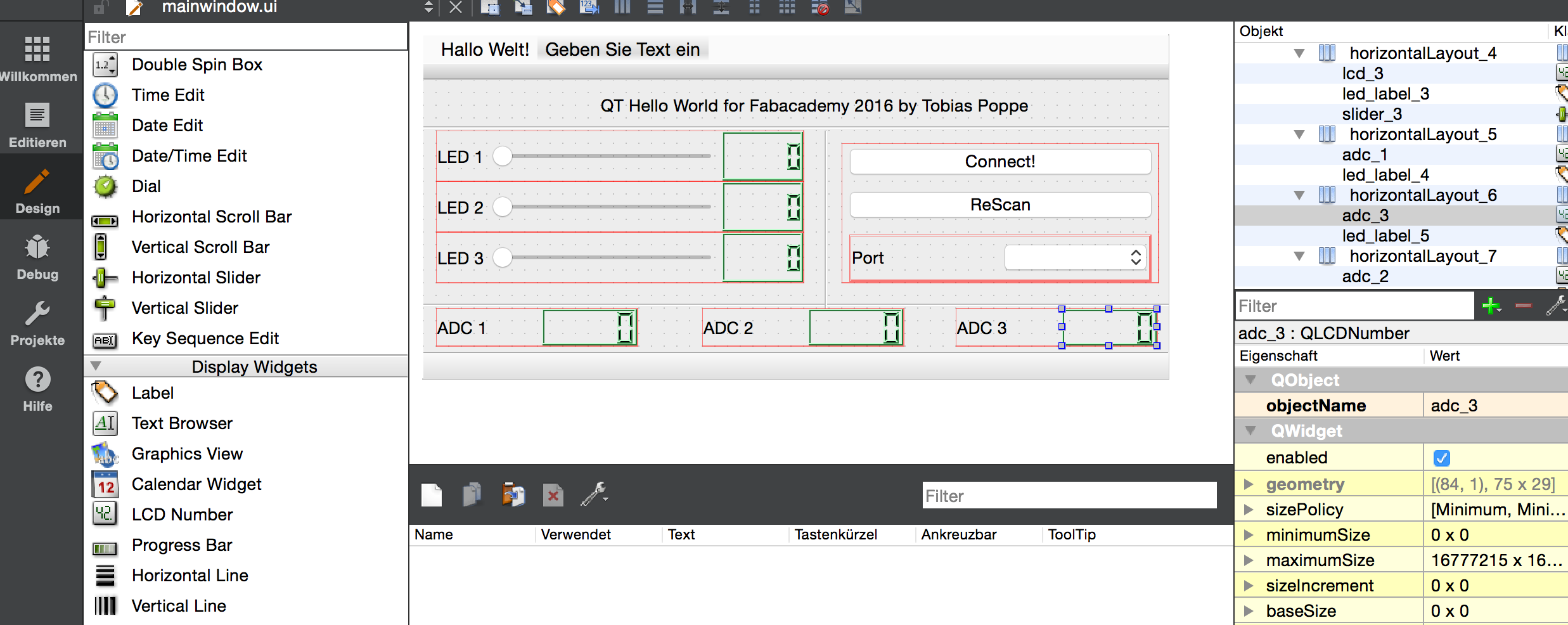
Every widget has a name and a bunch of settings and infos. These can be used in the c++-code by writing or reading from
ui->name_of_the_widget->setting so f.e. ui->slider_1->value() gives you the set value of the slider 1
With this said the code for the slider-send-out is self-explaining:
  void MainWindow::slider_changed()

  {

      QString buffer;

      buffer.sprintf("%03i;%03i;%03i\n",ui->slider_1->value(),ui->slider_2->value(),ui->slider_3->value());

      serial->write( buffer.toStdString().c_str(), buffer.size() );

      serial->QSerialPort::waitForBytesWritten(-1);

      ui->lcd_1->display(ui->slider_1->value());

      ui->lcd_2->display(ui->slider_2->value());

      ui->lcd_3->display(ui->slider_3->value());

  }
The three slider values are put together in a string seperated by ; and padded to 3 signs with 0.
After this a small lcd next to the slider is updated by the actual value
First task ready!
The incoming ADC-Values are in the same format and get written into the LCDs by:
  void MainWindow::serial_received()

  {

      QString received;

      while (serial->canReadLine()){

         received = serial->readLine();   //reads in data line by line, separated by \n or \r characters

       }


      QStringList splitted = received.split(";");

      if (splitted.value(0) == "A"){

      ui->adc_1->display(splitted.value(1));

      ui->adc_2->display(splitted.value(2));

      ui->adc_3->display(splitted.value(3));

      }

  }
Here i´ve done a little trick, because the UART-Buffer is often faster than the sender. So the program have to wait for a line with \n at the end before start reading the values.
One last thing you need to do, is patch the different signals from the GUI to your subroutines. This is done by running a "connect"-routine at the start of the program:
  {

        ui->setupUi(this);

        serial = new QSerialPort(this);

        connect(ui->rescan_Button, SIGNAL(clicked()), this, SLOT(serial_rescan()));

        connect(ui->connect_button, SIGNAL(clicked()), this, SLOT (serial_connect()));

        connect(ui->slider_1, SIGNAL(valueChanged(int)), this, SLOT(slider_changed()));

        connect(ui->slider_2, SIGNAL(valueChanged(int)), this, SLOT(slider_changed()));

        connect(ui->slider_3, SIGNAL(valueChanged(int)), this, SLOT(slider_changed()));

        connect(serial,SIGNAL(readyRead()),this,SLOT(serial_received()));

        serial_rescan();

}
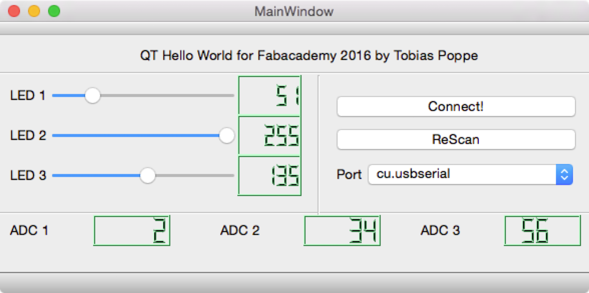
After compiling my new GUI starts and works perfectly:
For a second test i wrote a little program for the FabPic. To use it just connect two potentiometer to AD0 and AD1, and two LEDs to RC2 and RB5. The MPLAB-project-file is on the bottom of this page.
All in all it is a little bit complicated to get into QT, especialy if you don´t write c++ every day, but after a little time it is getting very easy and creative.
A very usefull tool!
If you want to, you can download my QT-Project here: qt.zip
And this is the MPLAB-Test-Project: gui_mplab.zip
Hope this will help you!
So long, have fun!