Project Development
The objective of the project was to build a glove and recognize some hand gesture and make track of the hand. I do know about electronics, so my first task is to start from the part that more time is going to take me: the design of the glove. The schedule for finishing everything is in two weeks (14 days). The project need a readjustmet.
- Glove Desing and Development - 5 days
- Input Device Development - 3 days
- Embedded Programming - 3 days
- Integration of Modules - 2 days
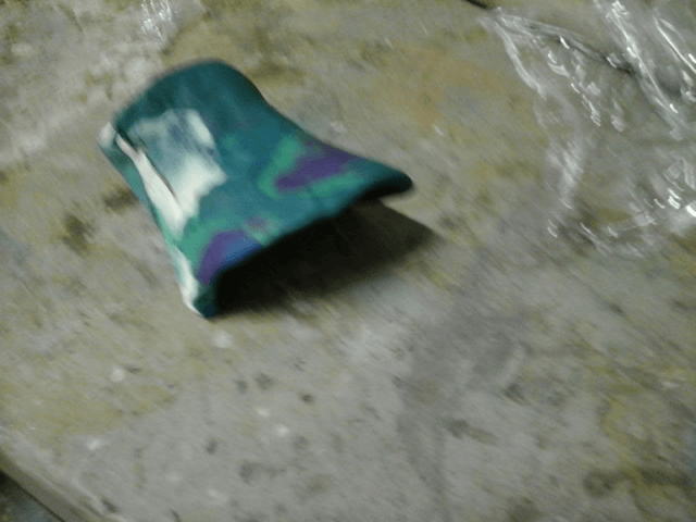
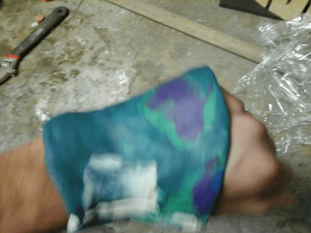
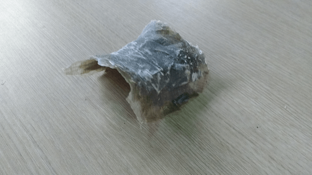

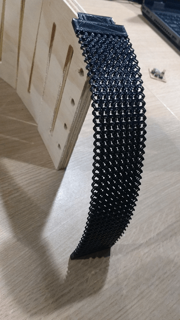
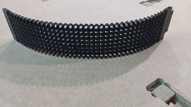
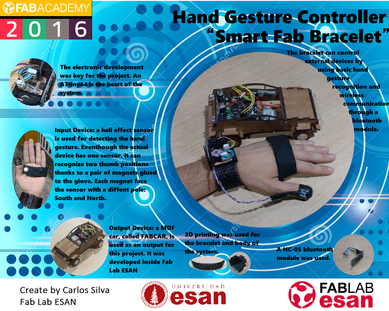
The result wasn’t good. It was uncomfortable and still to rigid for what I needed. Now what? It was time to think outside the box. A friend told me: Why don’t you print a bracelet intead of the glove… Marvelous idea. I found a bracelet model in Thingverse that was perfect for the job. The design was made by Gian Pablo Villamil, from San Francisco, CA.
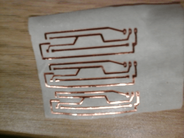
The next step was to make the input sensor. It was design to be placed over the fingertip. For reaching this purpose I printed a skullcap for 3 fingers. Then I design the circuit for collocating the hall sensor and cut it over vynil of copper. Those circuits were pasted over he skullcaps.


Afterward the components were soldered over.

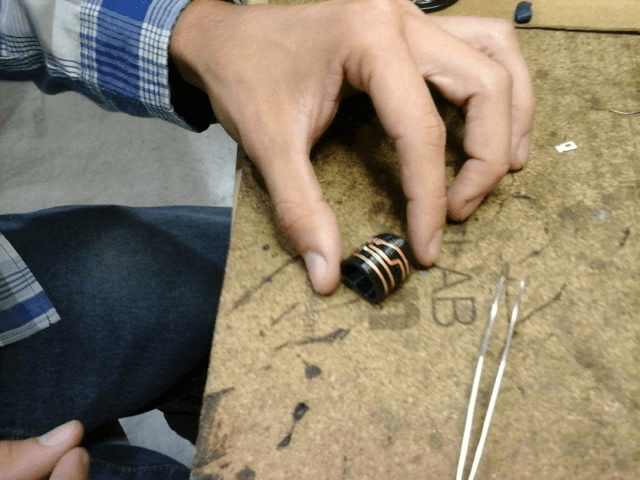
And test to see if they actually worked… The bluelight on the video appeared when the north pole of the magnet get close to the sensor.
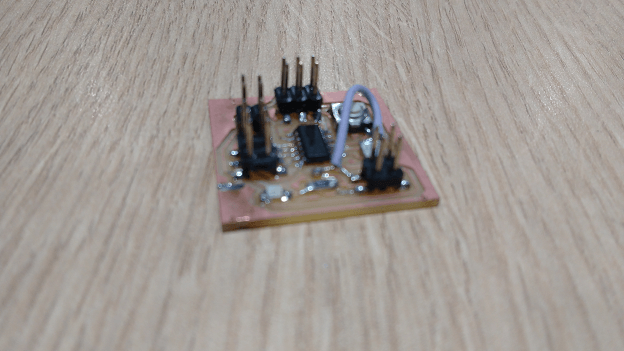
Now is turn for the controller. I used and ATtiny44 instead of an ATMega, as I initially planned. It was done because the problems I had with the milling machine and the soldering of the micro controller. For more information regarding the process of making the board, please check the assignment of Embedded Programming.
Adding the bluetooth module was easy. It was set it up as master. For doing that used the procedure on this webpage (http://www.martyncurrey.com/connecting-2-arduinos-by-bluetooth-using-a-hc-05-and-a-hc-06-pair-bind-and-link/). The next video shows the connection between my tablet and the controller by bluetooth.
The first issue: I wanted to use a MPU6050, an accelerometer and gyroscope module. However, it didn’t matter how many times I tried, the connection was wrong. After several hours of investigatión I get the reason: the board had an 8MHz resonator and the I2C library used for the communicaiton with the module assume a crystal of 1MHz and it couldn’t be change without loosing the serial communication (which was being used for the bluetooth). At the end I had to quit the idea of using the MPU6050.
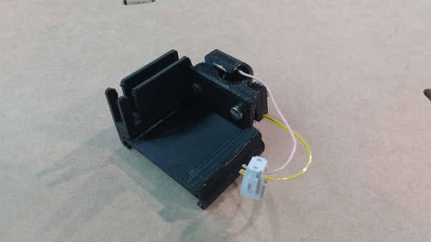
Lastly I designed the board support that would attached to bracelet. It contemplates an space for the bluetooth module and the battery support for 3 small round batteries of 1.5v each.
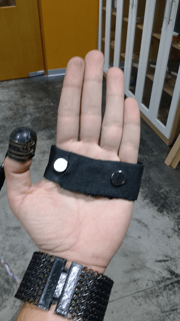
Finally, I needed make some sort of “glove” to paste the magnet. For that I just took some fabric and folded it several times to form a strip. I used silicon for pasting the magnets.
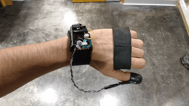
At the end, the whole integration of the system is showned below.
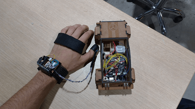
For the output it was used a small toy car built in the lab. The BOM of the projet is shown below. It is important to notice that most of the cost goes to the PLA filament. The electronic components are just a fraction from the total. My estimation is that in the whole device will cost around $ 40, as it was thought at first.

The license that is going to be used is the one from Creative Commons, because it hekops to legally share the information. That is important in order to get the full potential of this project where many people can contribute for its goal. In the next line the license is shown.

Smart Fab Bracelet by Carlos Silva Osores is licensed under a Creative Commons Reconocimiento-NoComercial-CompartirIgual 4.0 Internacional License.
Creado a partir de la obra en http://archive.fabacademy.org/archives/2016/fablabesan2016/students/57/FinalProject.html.
A presentation was made for synthesizing the scope of the project and the components used on the projects - Presentation
For viewing the prototype working please go to this link - Video.