Electronics!!!!
Not my particular favorite, but necessary, and things will only progress and get harder. So why not master the basics first, right?
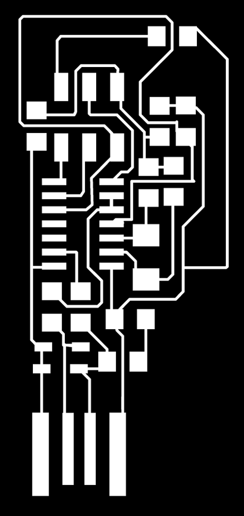
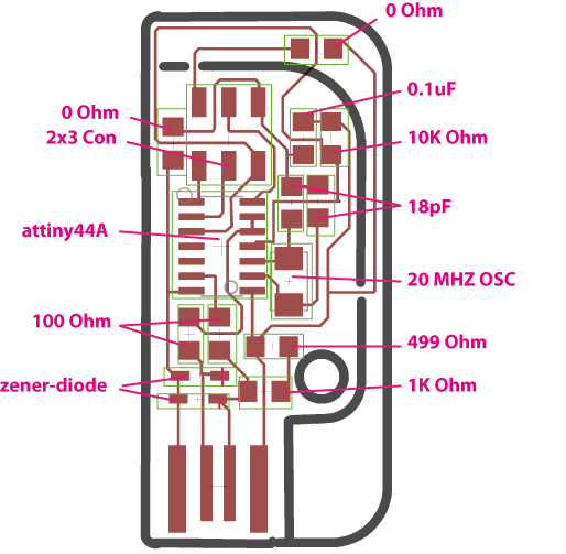
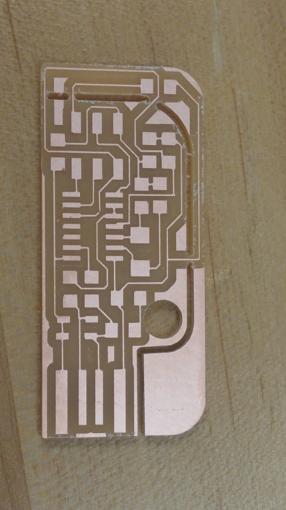
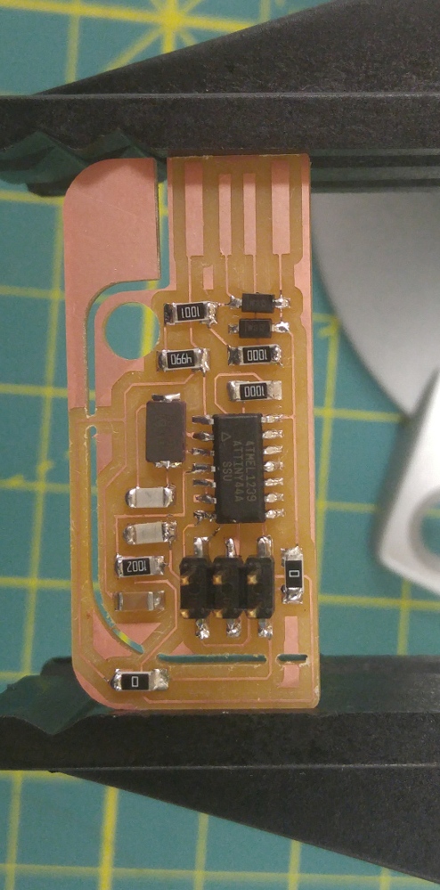
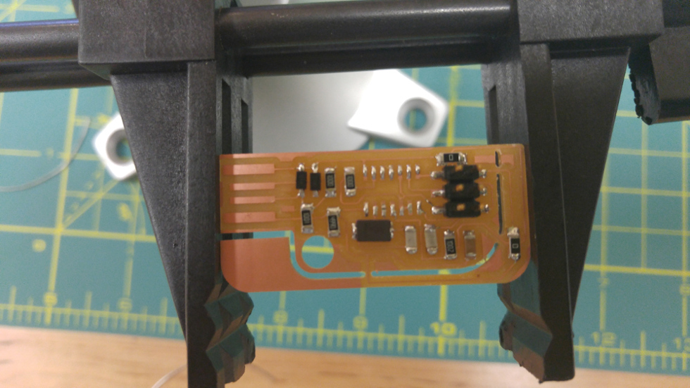
This week's mastery challenge is to mill any version of the fab in-circuit programmer, build it with the necessary components, and program it (for future projects). The programmer that caught my eye is the design created by Valentin. I like for anything that I make to be precise and in pristine condition. The aspect of this board that I like the most is being able to disconnect the jumper rather than desoldering the resistor once it has been programmed. So let's see how it goes... Before milling the board, one of the most important things to do is to gather and familiarize myself with all material/components needed. Parts for my specific board (and may apply to others) are:
- 0 Ohm resistor (two)
- 0.1 uF capacitor
- 6-pin header
- 10k Ohm resistor
- 18 pF capacitor
- Attiny 44A microcontroller
- 20 MHZ resonator
- 100 Ohm resistor (two)
- 499 Ohm resistor
- 3.3v zener diode (two)
- 1k Ohm resistor

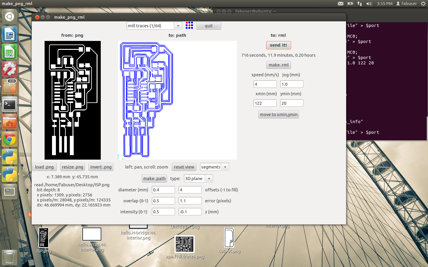
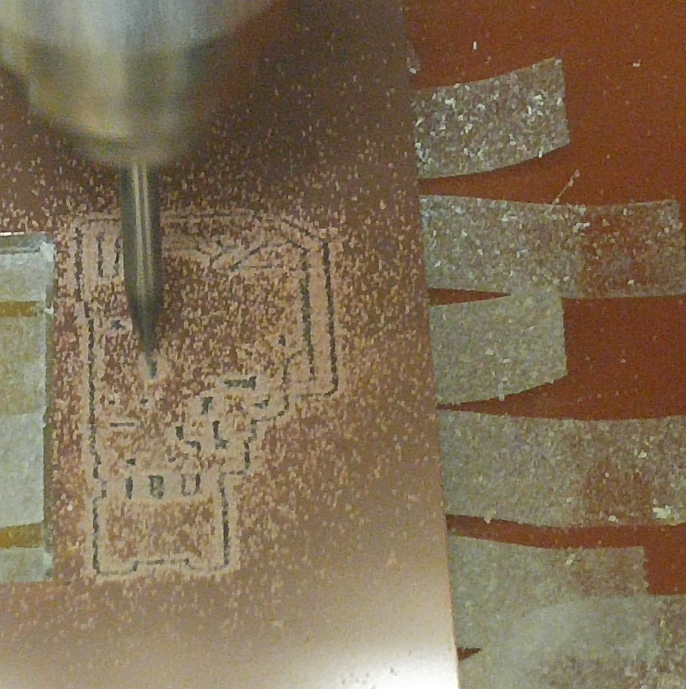
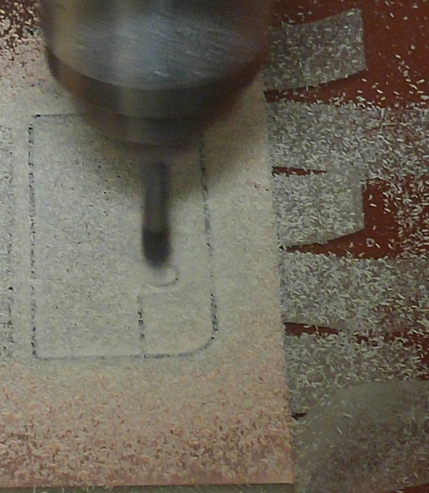
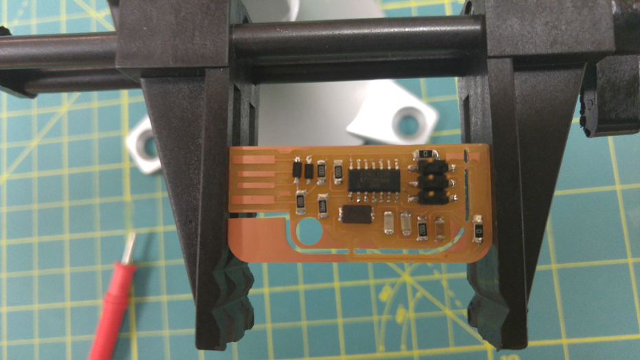
Overall, I am highly satisfied with my results thus far. Beginning from downloading the files, the setup process for fab modules, milling and the finally stuffing the board, I experienced an easy step-by-step transition. The one (and only) downside within this part was that I was not able to use the fab modules interface due to some difficulties with installing it; so I used the previous fab modules version (see pictures). But, there will be more boards to create so I know I have time to get everything in place so that I can use the newer fab modules in the future.
Programming...

When beginning the programming process, the first step is to identify how you want to program your board and with what. I also learned that prior to programming and after the board is built, when the (unprogrammed) board is connected to the computer via usbtiny programmer or AVR programmer, use a multimeter to make sure your board is receiving power. One additional signal is the green light on the programmer. After downloading the necessary files, I went into the makefile to tell it how to program my ISP. The above image is the statement that must be edited in order for the programming/programmer to work. While going through the programming process, make fuse and make program were my hardest steps to overcome. Because I thought I knew where pin 1 was when connecting the usbtiny programmer to my ISP, this week's assignment spawned more issues (as well as solutions) to my learning process.
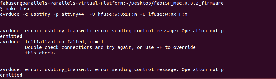
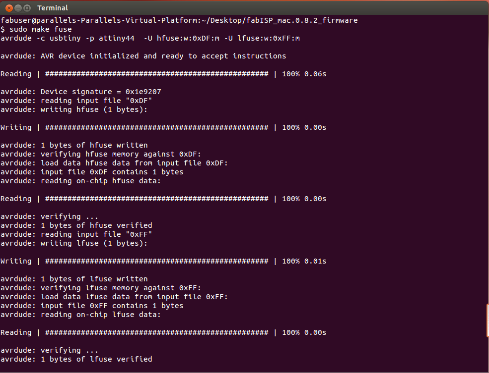
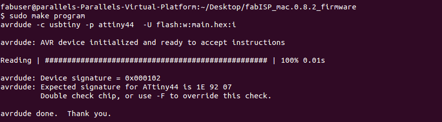
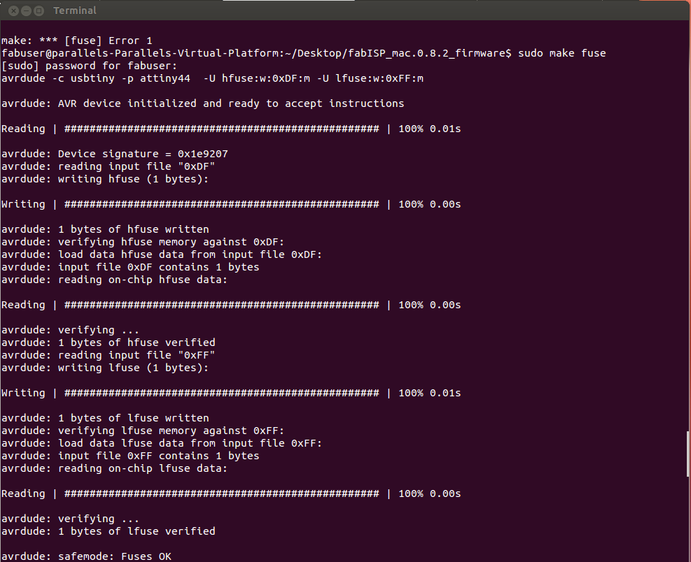
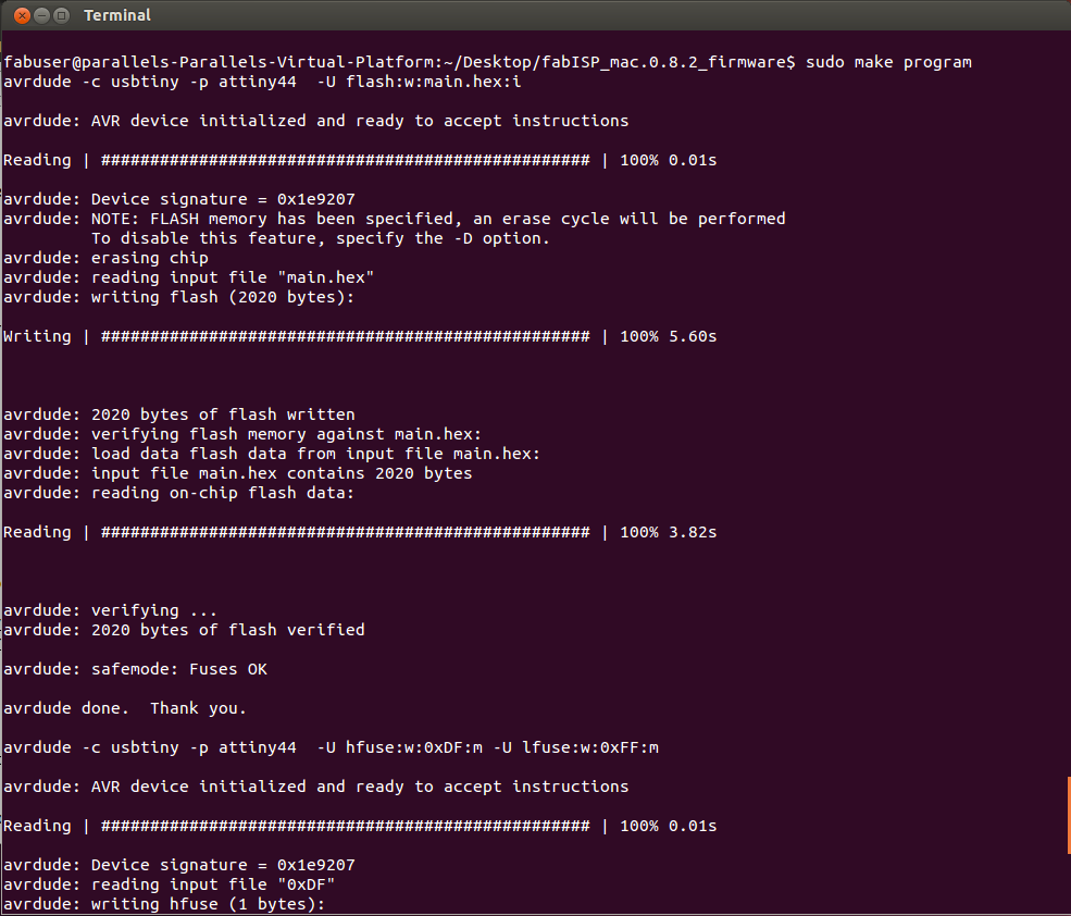
During make fuse I received the above error message once. I examined my board to make sure that all of my connections were correct, and tried "make fuse" once more and received the message (see middle image). Once I was confident that my board had the fuse, I did "make program"; during this step I received another error message (see right image). At this point in my programming, (1)my connections between components were good, (2)my board was receiving power, (3)it made fuse-- I assume, so why was it not making the program? I eventually had to work backwards doing some hierarchal problem solving. SIDENOTE: Although there are some asthetics to the Valentin board that are different from Neil's board, they are somewhat essentially the same.
Upon further discussion with other lab associates, it was concluded that, because I was receiving back this error message, I had fried my microcontroller burning the fuses because I had situated my 6-pin header wrong and was continuously trying to make fuse. :(. So I had to desolder my microcontroller and attach another. Thankfully, detaching replacing microcontrollers was not as big of a deal as I thought.
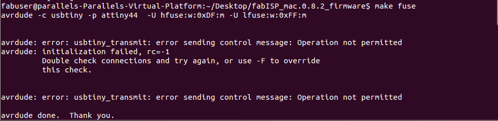
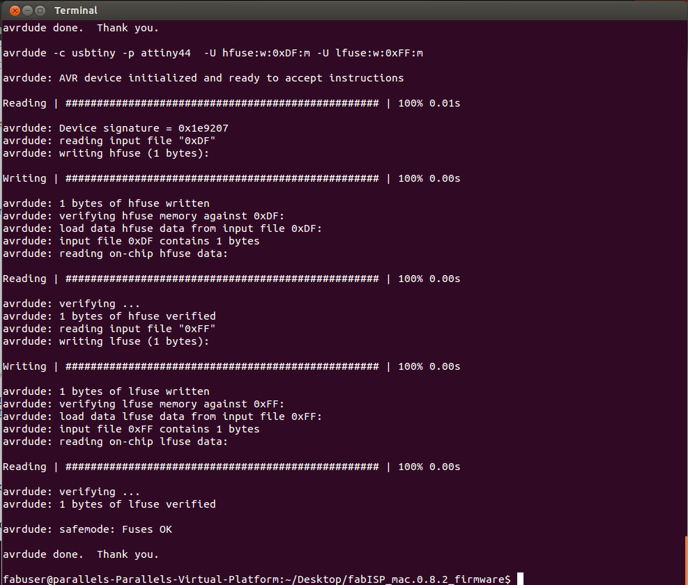
Once I was back at make fuse and make program, I carefully looked over my images and attached my board and programmer. I was sent the above image error message after make fuse. I tried sudo before make fuse and it was a success.
Learned lessons: Overall this was a good experience (especially for the first module of electronics). My most important take-away is NO GUESSING. When you assume, you have a 50/50 chance of right or wrong; (at least for me) I always end up choosing the wrong answer. Plus, you waste time if your answer is wrong and can cause future debugging issues and we only have so much time for each assignment. Lastly, for individuals using Valentin's board, locate pin 1 first. To help ease your mind, pin 1 is connected to PA5 of the microcontroller which is directly on the same side of GD.