More electronics!!
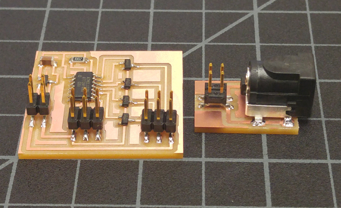
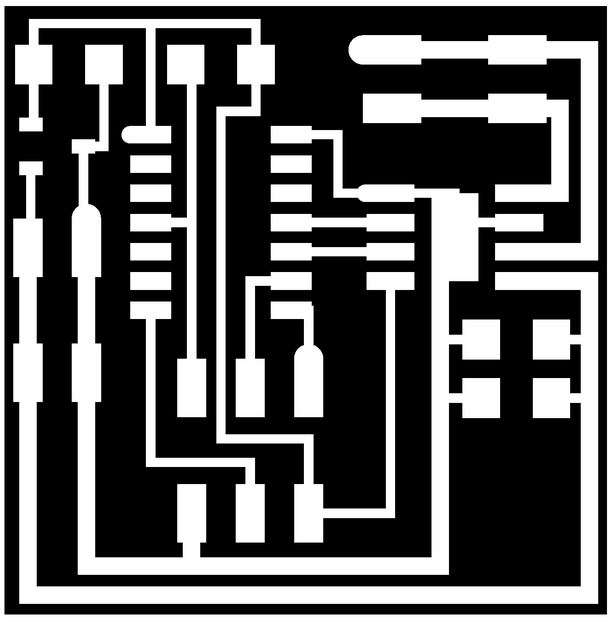
For this week, we are adding an output device to a board of our choice while still designing the board ourselves. I am currently still undecided about the motor that I would like to use for my final project, so I've decided to explore the stepper and DC motors because I think they will be beneficial to understand for the future. To begin, I milled out Neil's DC board (just to get general knowledge about how it works) and I created my own stepper board in Eagle.
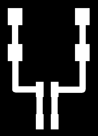
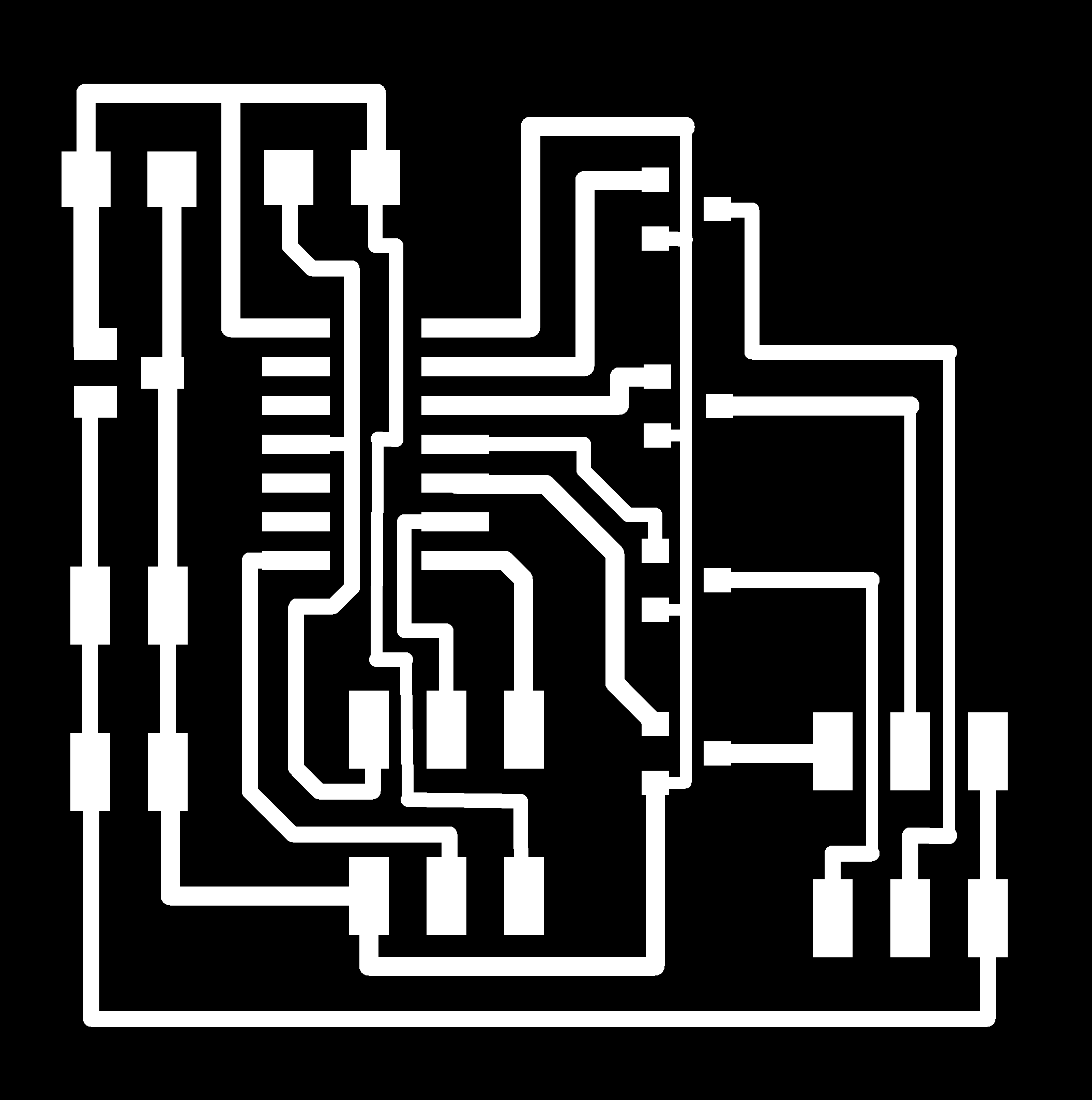
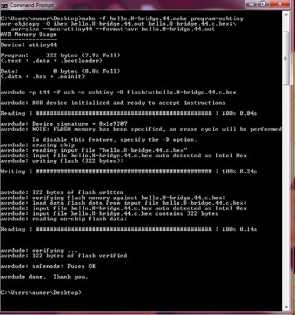
After successfully soldering both boards, I also created a power source (using the power jack and a 4-pin header) so that once each board and motor were connected and programmed, the motors would run seperately. For programming, I started out with attempting to program the DC board in Windows with the WinAVR program. Unfortunatley, I had some issues: receiving error messages stating, "Could not find USBtiny device" or "initialization failed, Double check connections and try again". After some investigation, I figured out that at this point with the use of multiple ribbon cables, one needs to be sure that
- GND and VCC are connected to the right pins
- if wires are needed with motors (i.e. a DC Motor), be sure to be able to recognize HIGH and LOW
- if operating in Windows and the program continues to give the message of not being able to find the USBtiny device, a trick I found useful is plugging and unplugging and/or interchanging the port that you plug your USB in
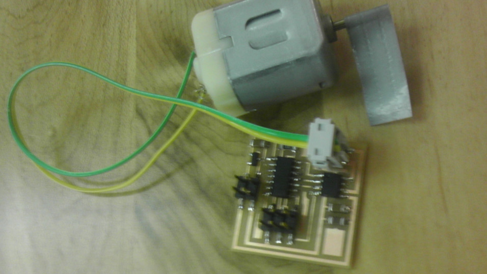
After all of my troubleshooting, I was able to get my DC motor board running. Although I was unable to get to my stepper board, I will go back and possibly use as my motor board for my final project.