Computer-Controlled Machining
Assignment:
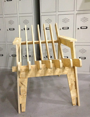
Make something BIG!!!I decided to make a chair :)Design the chair.
During this week we have been learning with Rhino / Grasshopper & Solidworks
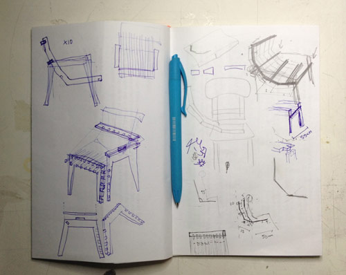
I started the design process visiting this site. With some referents I began to sketch some ideas on my sketchbook
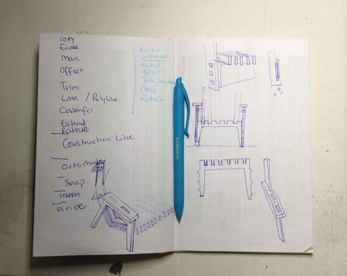
Thinking about the whole chair and the press fit joints. Ergonomics was also an important issue.Despite I don't like Autocad I used it as a digital sketch tool. It is fast and precise. I will try to bypass the "nasty" .dxf file with Rhino. The next image shows my first sketches, I decided to change this design because the angle on the chair back was not good enough and comfortable.
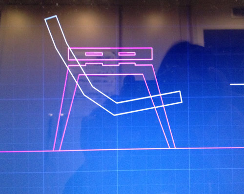
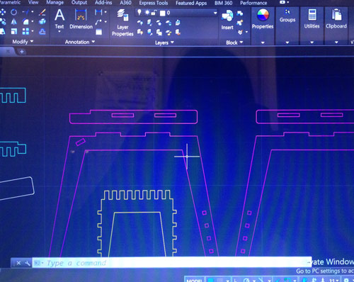
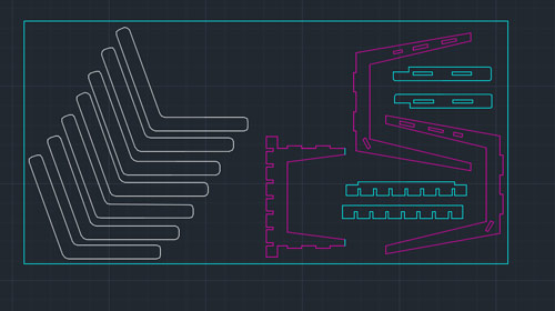
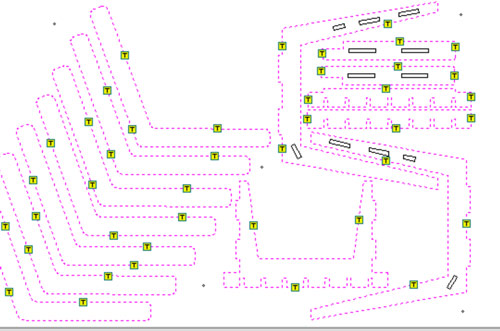
I imported the vectors to Rhino to make an ide how design was evolving.At this point I decided to change the design. More details of the 2D drawing, the next images shows different parts of the chair.Here is the final Autocad design with the shapes separated in different layers.
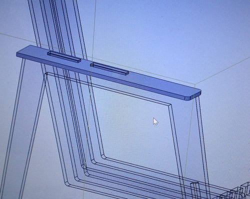
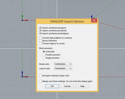
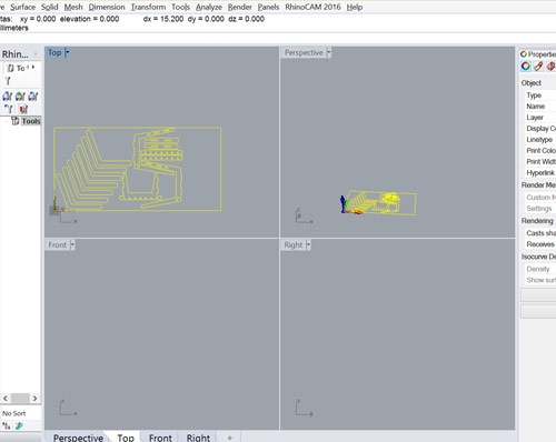
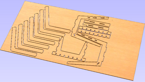
The Autocad commands I used are: copy / move / erase / offset / trim / line / polyline / chamfer / extend / rotate / construction line / orto mode / snap / stretch / divide.I also used SolidWorks to visualize the design, but I did not finish the model, was just to make an idea of the model in a 3D view.Once saved the .dxf I imported to Rhino.The commands I used in Rhino are: extend / offset / join / explode / move / rotate / make2D / export selected --> dxf With all the vectors joined, nice and clean is time to import them to Partworks for generating the .vcr file and export the gcode for the Shopbot milling machine. Partworks is totally new for me, and I'm not used to the interface, so it was quite challenging to get into it. Thanks to the instructors that guided me through the hole process:
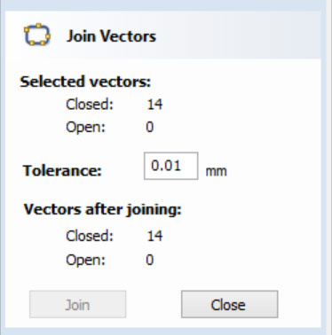
1. join the vectors all together in case there are some not grouped, you can see this when you click on a vector and it does not select completly in a pink dotted line.
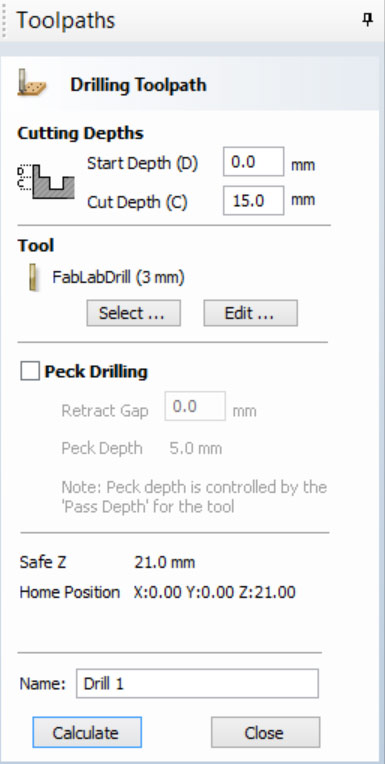
2. create drills with the properties we will be using.
3. create definitions: 1st for the screws, 2nd for the interior cuts, 3rd for the exterior cuts.
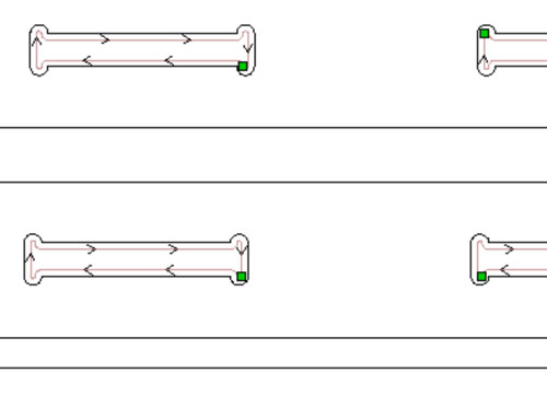
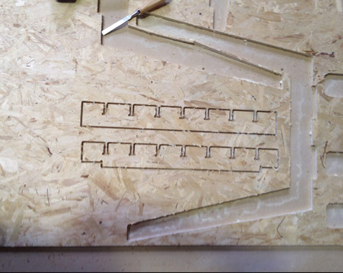
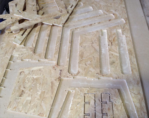
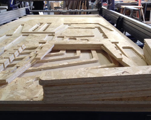
4. create the tabs, this way we ensure the cuts will not move thanks to the bridges. 5. export the gcode.
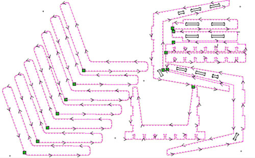
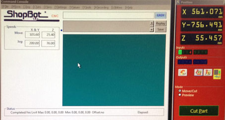
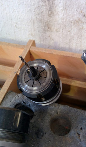
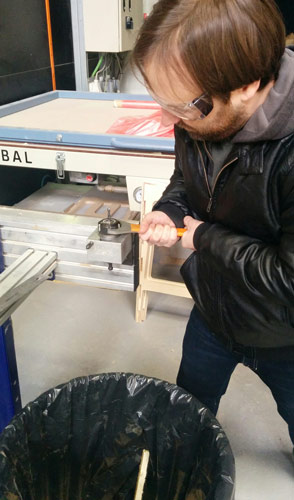
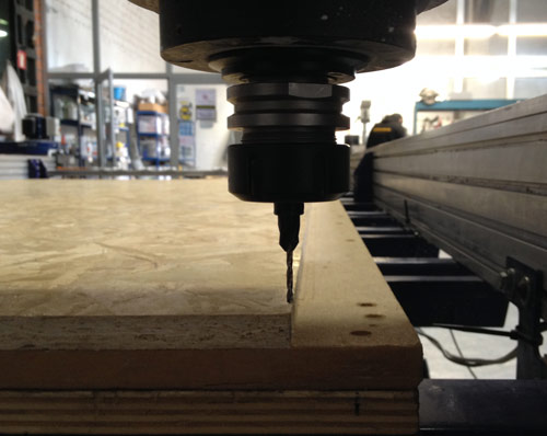
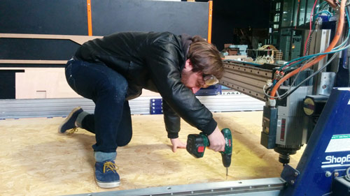
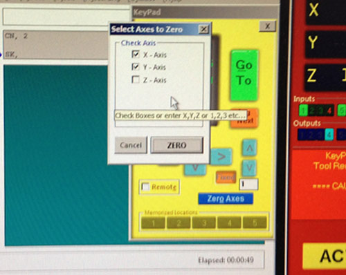
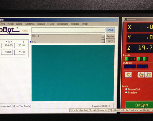
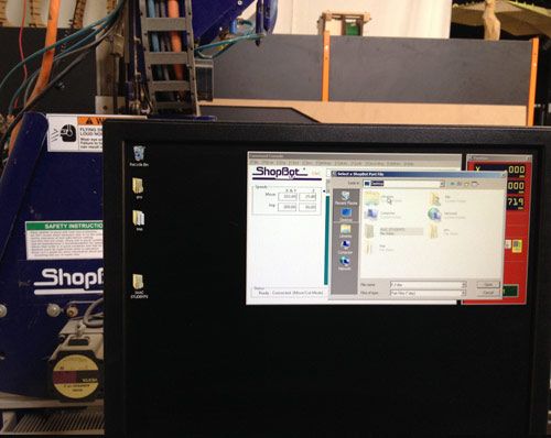
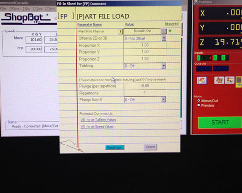
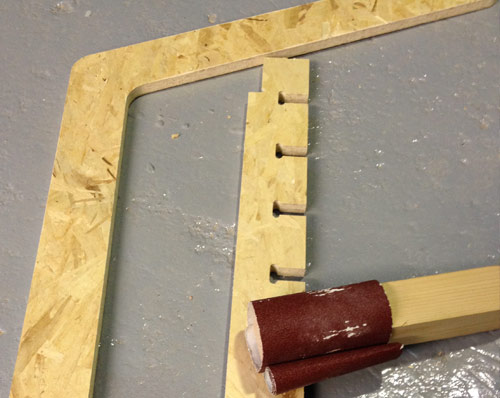
Finally, there's an option for checking how the drill will move along the board.Now it is time to visualize the tabs.We have a preview image of the cutsWith the gcode is time to move to the Shopbot. Prepare the machine and load the file. Zero the axes and select the appropriate drill.The milling machine is precise but the edges have wood chips and need to be sanded.Just a quick reminder, check your .crv file (if you are using Partworks). I had an extra cut in the cut layer and I did not realize until the Shopbot was milling, luckily nothing happend, but you can break your milling bit.This is the chair with all the parts assembled!!Next week, embedded programming, sounds interesting!!! :)Download the files here