Electronics Design
Assignment:
1. Redraw the echo hello-world board.2. Add (at least) a button and LED (with current-limiting resistor.3. Check the design rules, and make it.Redraw the echo hello-world board.
First things first, I focused on Eagle software, it is quite professional, cross-platform maybe the only negative point is that it does not have simulation tool for the circuit. You can download Eagle here. You can use it as a freeware.
The next step was to download the fab.lbr file (fab library) and drop it into the libraries folder in Mac OS under, Applications/Eagle/lbr. I also installed the Adafruit and Sparkfun libraries, available at their sites. To activate the libraries launch Eagle software and go to libraries/use.
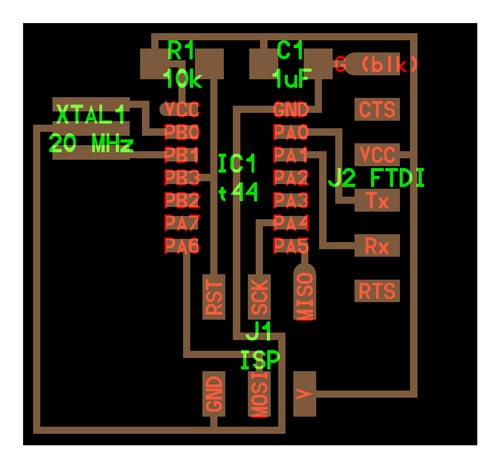
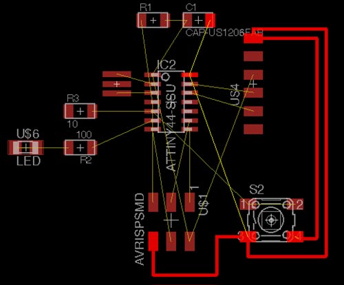
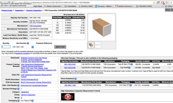
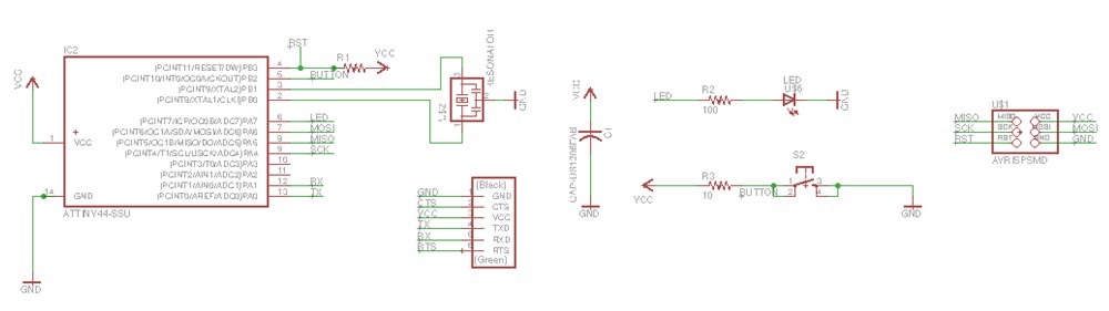
Now it's time to get into business. Taking the Neil's reference image, first step is to make sense on what every component is: 6 head jumper FTDI, Attiny 44 SSU (the same microprocessor we used two weeks ago), 1 Ceramic capacitor with 1 microfarrad, 1 resistor 10K, 1 resonator 20Mhz, 6 head jumper ISP. And we have to add: 1 switch button, 1 LED 1206 and 2 resistors (one for the button, and one for the LED).
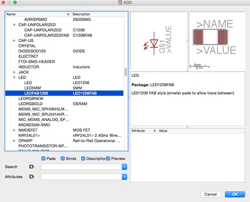
Inside Eagle, the idea is to create a project, inside this create a schematic file. On this file we have the add button on the left toolbar, then a window pops up. This is the libraries window where you can add all the components you need. Starting with the ones we allready know, navigate to the fab library, and click on the component you want, once you selected the component click ok and click on the schematic view to add it.
I followed the FabAcademy tutorial.
The main idea here is to realize what else you need, for instance, you will need to add GND (ground) and VCC (voltage).
My list of components is:
1 x 6MM_SWITCH6MM_SWITCH
2 x 10 ohm RES-US1206FAB
1 x 10 k RES-US1206FAB
1 x ATTINY44-SSU
1 x 6 pin header AVRISPSMD
1 x 1 uF CAP-US1206FAB
1 x LED 1206
1 x 6 pin header FTDI-SMD-HEADER
1 x 20 MHz RESONATOR
In my case, all of them are surface components, the red icons, like in the FabISP board (no through hole green icons).
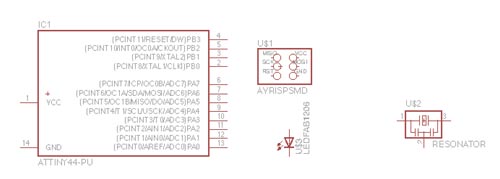
First you drop all them on the schematic view. Once, all of the components are there, it's time to create the conexions. Some useful commands are: move (left click), rotate (with the object selected, right click on the component), select group (with the group selected, and right click on the gropu we can select the option move group), net (for creating the connexions), name (to name green wires, conexions with no need of creating the physical wire that connects the components), label (names visualization), value (to give value to the components, very useful for resistors, capacitors...), change and info.
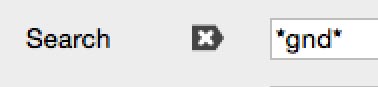
If you need to look for a component, you can use the search on the libraries window. It is required to write this way: *component*
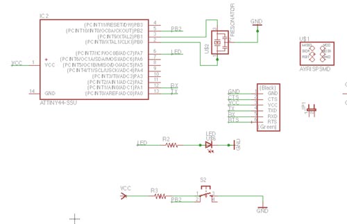
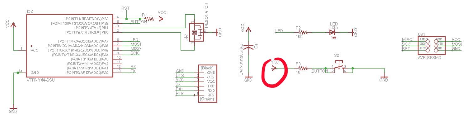
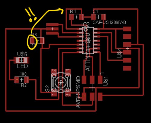
You should be carful everything is well connected. At this point, I had an error, you can see it in the next picture. The VCC is upside down.
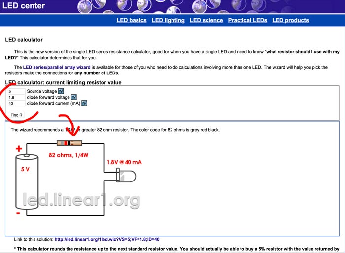
I very useful to do it now, otherwise you will need to do it later, to calculate the Resistors values depending on you Voltage and your LEDs. I used this site. You should use a Resistor with same value or higher (Never less than the value the LED calculator recomends you). If the value is so high the LED will be emitting less light.
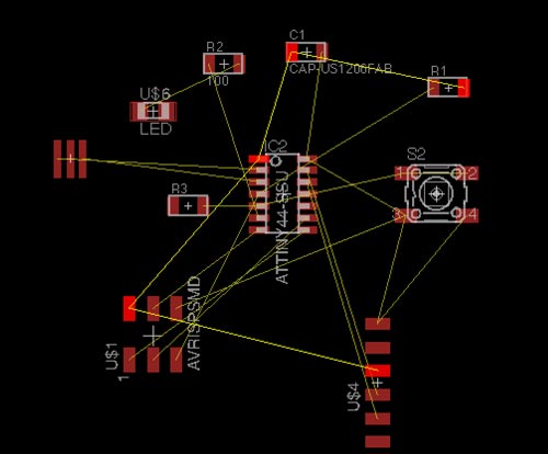
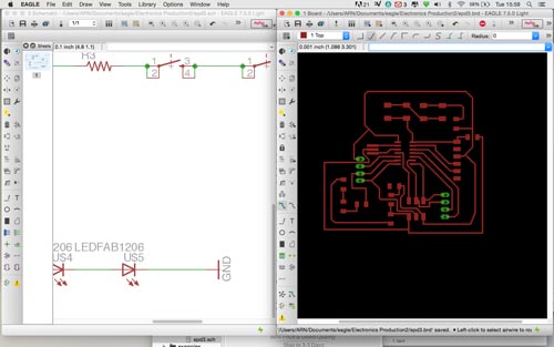
Once you are done with the schematic view, press the go to PCB view on the top toolbar, and Eagle generates a window for you to design all the traces with the components you dropped on the schematic view. Bridge traces between the components (like the button or the Attiny 44) will be necessary.
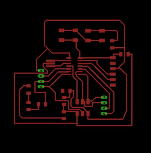
Place all the components inside the white square. Here, you can use some tricks, like placing the elements like Neil's board. For example, the microprocessor with the tiny o shape on the top left corner. And the ISP header on the bottom, with the GND on the bottom left.
It's time to start tracing. You will need to tweek, rotate and move the components around to allow you to make your traces easier. The eye icon and the trace and delete trace are the tools that you will be using for this part.
My mistake on the schematic view, is now visible here. Everything must be connected, and my resistor has a pin that should be conected to the VCC. No problem, you go back to your schematic view and change it, changes are updated in real time.
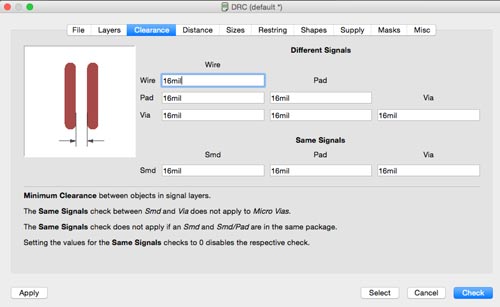
When you finish tracing you should type the DRC (design rules check) command and press entera window will pop up. There's another comand ERC, but is not as important as the first one. The DRC command opens a window, you should go to Clearence tab, change the 8 mil value for 16 mil all the values and click on check. If no window pops up and at the bottom left corner of the Eagle PCB window a message appears with NO ERRORS, congratulations you can export the .png file.
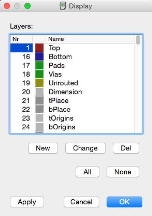
After checking the DRC, you should click on the layer icon, disable all layers. And then select the first layer -TOP- (the one with the red traces). Whether you may have a bottom layer -TWO- (with blue traces), you should select it as well. This will get rid off all the information but the circuit traces.
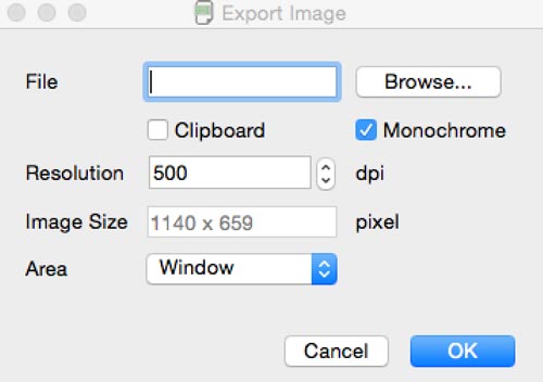
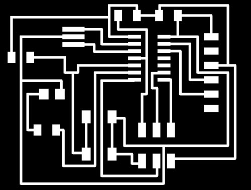
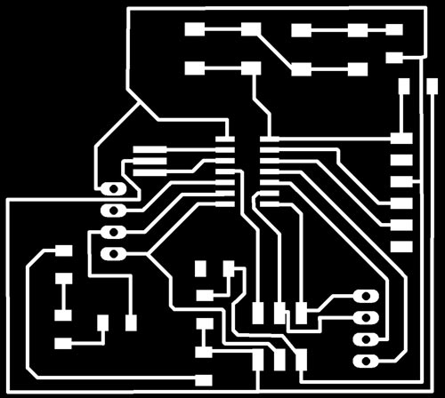
The next step is to export the .png you should navigate to File/Export/Image. Check monochrome option, 500 dpi - or more - select the window option. And save your file in a specified folder. This will generate a image pure black and pure white, like the one you see here.
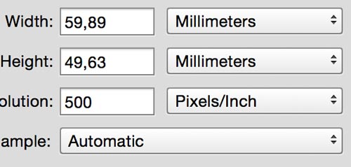
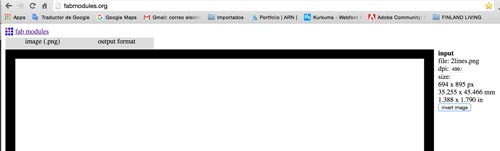
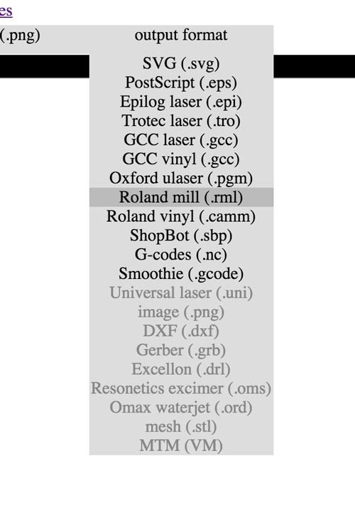
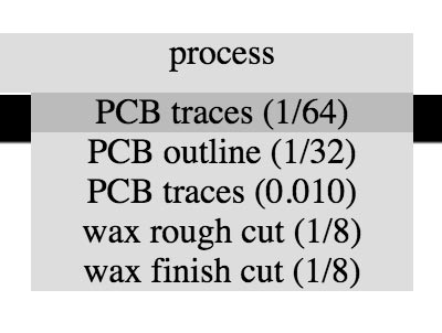
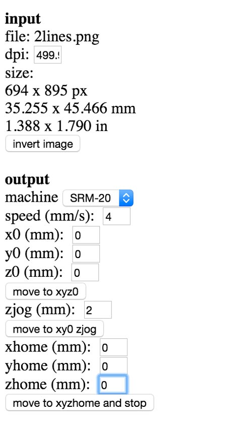
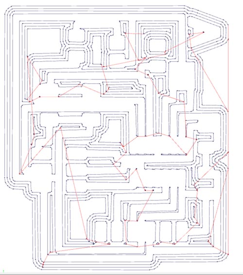
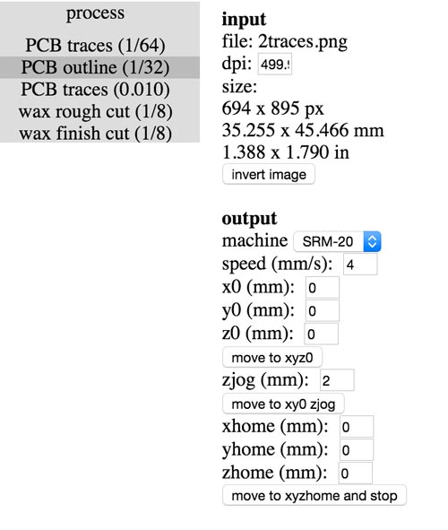
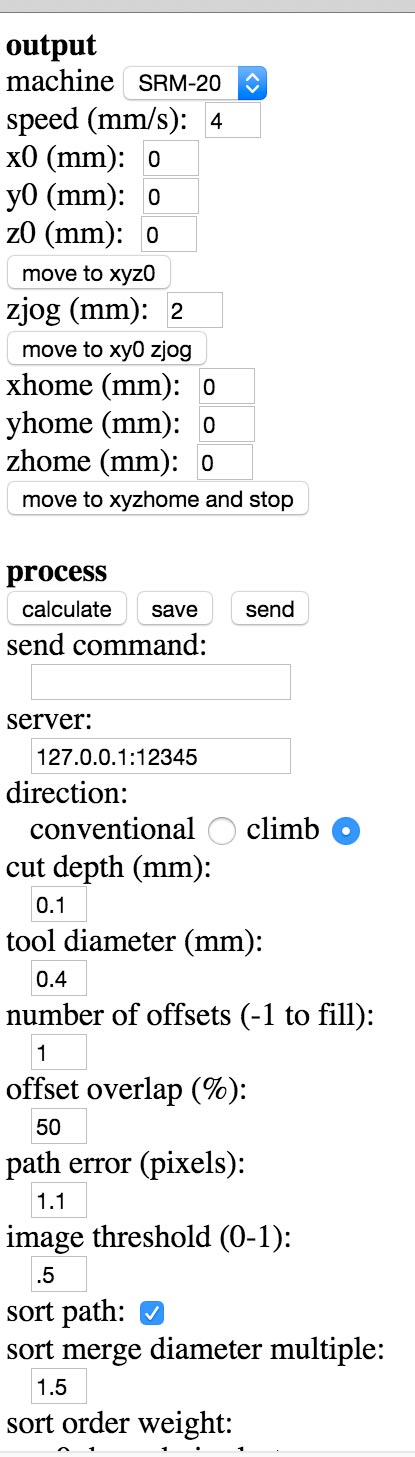
Now, it's time to generate the outline. Open the file in photoshop or gimp. And make the canvas bigger: 16 mm for each side. Be sure you don't accidentally change the resolution of the image, or change the file to greyscale (the file should be pure black and pure white until the end of the process). The outline (8mm) should be black and the interior white. Export the outline, and export again the circuit traces 8with the new canvas size). At this point you should have the .png files with same canvas size.Now it's time to generate the gcode. Using fabmodules website upload the .png files, select the process 1/64 for milling the traces and 1/32 to cut the outline. In Fablab Barcelona we are using the monoFab Roland SRM-20. And the settings are:
For the 1/32 milling bit the settings are:
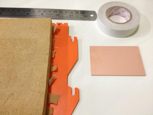
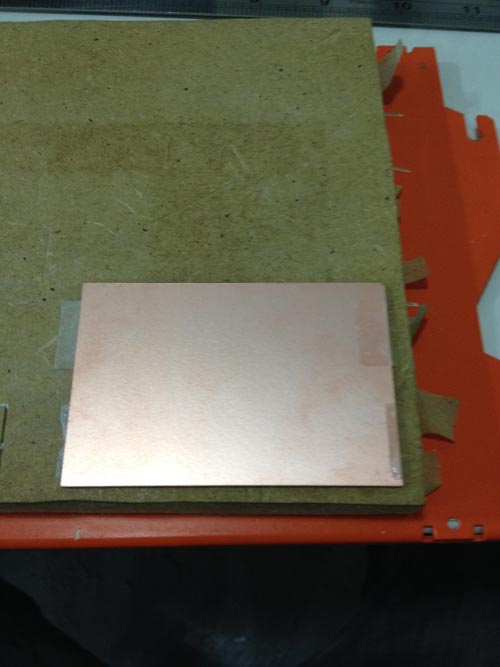
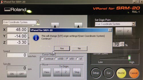
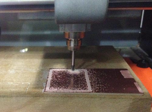
We have .rml files with the gcode, now it's time to place the board into the milling machine. Set the home on x, y and z.
Select cut option on VPanel for SRM20 software for milling the board. Upload the .rml files to the VPanel software.
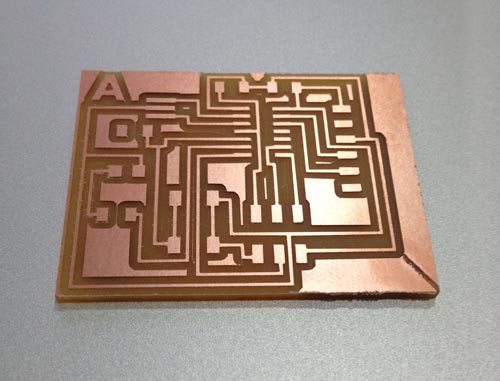
This is the finished board.
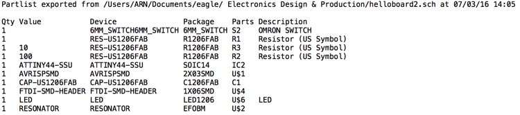
Before grabbing all the components is good idea to export the Bill Of Components from Eagle, type the "run bom" command press enter and in the window that pops up select text file, value and click safe. This is my Bill Of Components:
Once you have the list you need to check on the data sheet the specifications of each component.
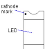
There are some components (like the Attiny 44) that orientation matters, another one is the LED the anode and the cathode. In my case I searched on google the LED I used, and then look for tiny dot on the side, indicating the cathode (GND).
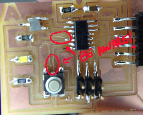
I had some problems with some thin copper and I needed to remover manually with care. I did it once the soldering was finished, better do it before soldering.
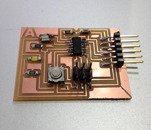
The board finished.
Now I'm still working on a second board with two buttons, three LEDs and two and two pin heads with a 4 hole through.Download the files here