Electronics Design
Assignment:
Embedded programmingRead the ATtiny44 datasheet.Program your board to do something.Read the ATtiny datasheet
During the lecture I realized that (for newbies like me) the datasheet should be read as a reference guide. It can not be read as book is better to skim through, just to know what the components are and some specifications, to get an idea of what you can find there. And come back later as your knowldge grows.
Program the ATtiny44 with Arduino IDE.
Install the Arduino IDE, download it from the Arduino website.
The next step is to load the Attiny package into the Arduino, the reason of doing this is because, by default, ATtiny boards are not included into Arduino Board manager.
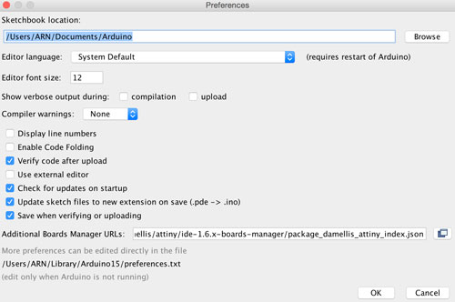
"Arduino - Preferences"
Find “Additional Boards Manager URLs”.
Paste the following URL into the field (use a comma to separate it from any URLs you’ve already added): https://raw.githubusercontent.com/damellis/attiny/ide-1.6.x-boards-manager/package_damellis_attiny_index.json
Click OK to save your preferencesOpen the boards manager in the "Tools - Board - Board Manager" menu.
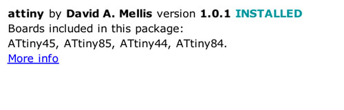
Scroll to the bottom of the list, select the ATtiny. Click on the install button on the right side.
The word "INSTALLED" should appear.Navigate to the "Tools - Board" and select the ATtiny
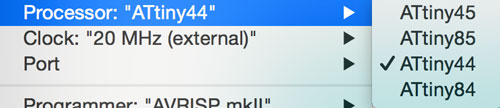
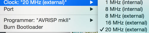
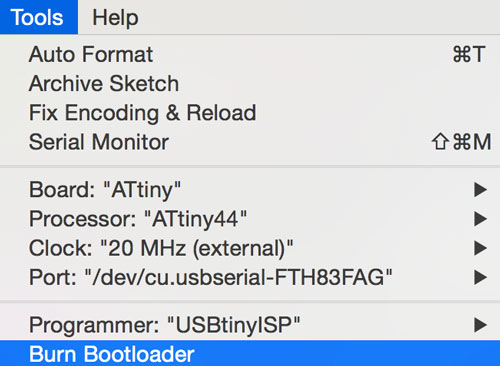
Now it's time to select the ATtiny44 Processor, the 20MHz clock, the USBtinyISP Programmer and the correct port (your USB port)We will, come back here later, now we need to make our 6 pin header cable, we will connect the hello board and the FabISP board with the cable. The latter will be used to load the program on the former.
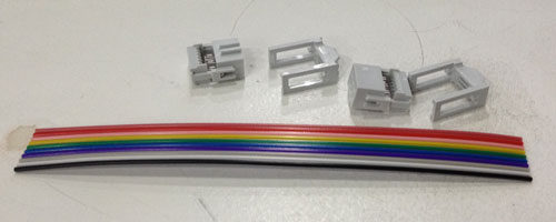
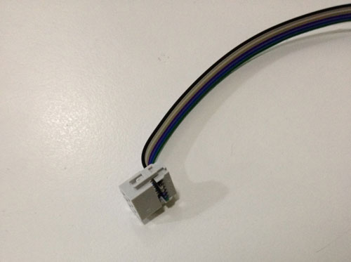
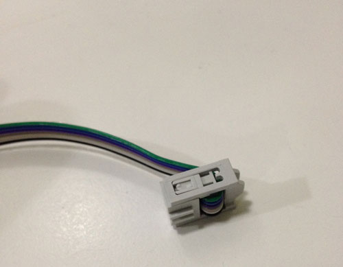
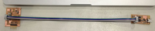
Making the cable:
We need 2 x 3 female connectors, and a 10 wires cable, will reduce it to 6.
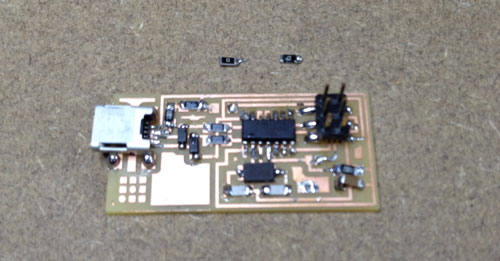
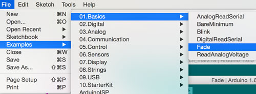
I had to desolder the 0 ohms resistors (jumpers) from my FabISP, because I did not do it two weeks ago. With the tweezers and the soldering machine heating one side you can desolder easily.Now is time to connect both boards, with the 6 pin cable header, the GND from the 6 pin header should be connected one to each other.We connect the FTDI to USB cable to the hello board, the GND cable (black) should be connected to the GND pin as in the picture. The USB side on the computer. And, of course, the FabISP connected via USB to the computer.Now it's time to come back to the Arduino IDE, and navigate to "Tools - Burn Bootloader". If the boards are well designed, and there's no problem with connectivity or circuits. We will get the message: "Burn Bootloader done".Now I loaded a simple Arduino example. File - Examples - Basic - Fade.It is important to take in consideration the difference between pins in ATtiny and Arduino.
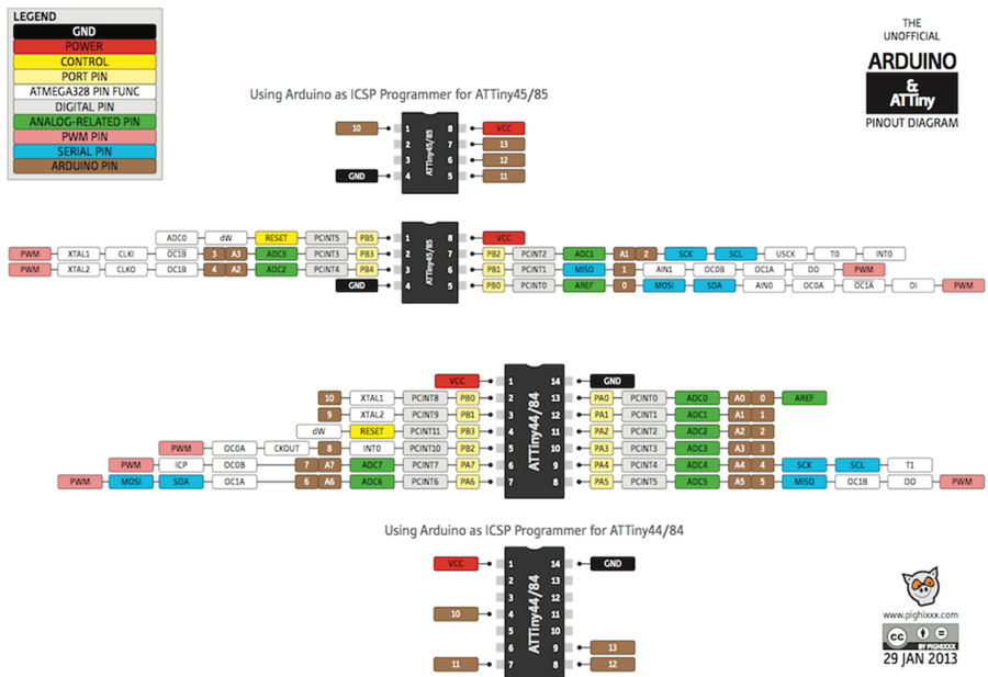
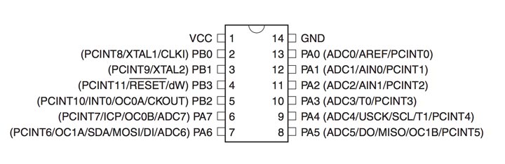
I googled: "Arduino ATtiny" and I found this useful diagram which explains the equivalence between pins in ATtiny and Arduino boards.So, you need to change the code in the example, to match with the pin in your board, in my case, I got the LED connected to the ATtiny pin 6, so in Arduino is pin 7.The password for the video is fablab
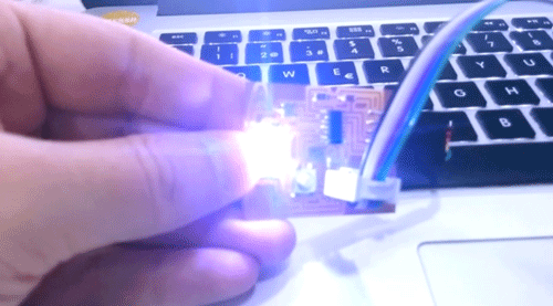
The first shooting is with the arduino fade example. The second is the LED turning on and off when you press the button.Download the files here