Week 11: Input Devices
The Recitation
No recitation this week.

The Lecture
Machine Design review and Input Devices lecture by Neil Gershenfeld can be found here.
The Assignment
Adding a sensor to a microcontroller board that you have designed and reading it:
-Designing a board with a sensor

-Surface soldering the components

-Preparing the board for use

-Actually make it work (The importance of this will be apparent very soon)
Designing the Board
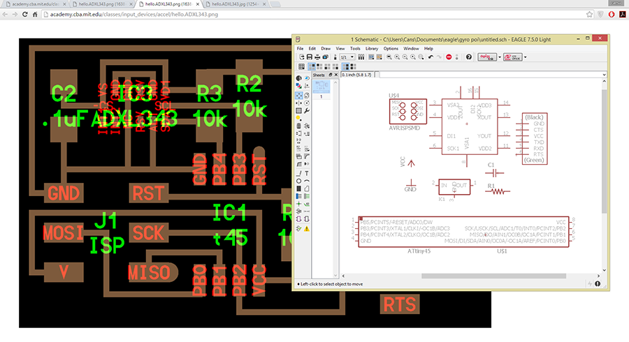
I decided to make a board for a 3D acceleration sensor that I will use in several things, including hopefully my final project. I started fiddling with the example files.
I was working on this board when I remembered that this accelerometer wasn't in the inventory anymore. Then Herr Meier confirmed my suspicions, bless his soul, and saved me a lot of frustration later on. Lesson learned: Check components before you start designing! Check whatever before you actually start working, in general.
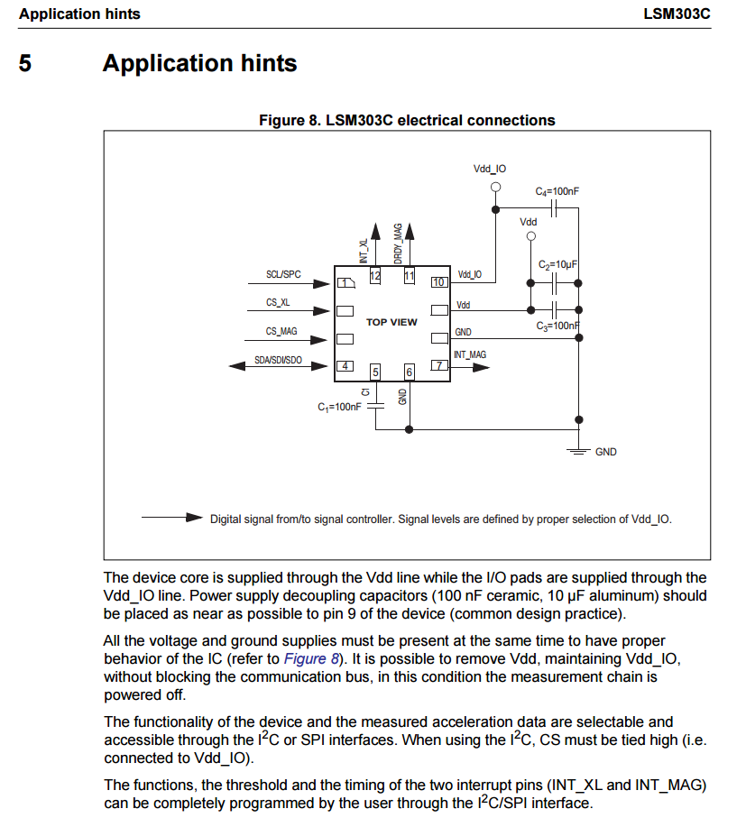
Of course then I started looking around and started reading up on Gabriel's documentation from last year. He has helped me a lot in general through the week. After reading through his documentation, I started to read the datasheet for the LSM303C 3D accelerometer, which was great and not scary at all, I swear I wasn't intimidated by a .pdf document.
The datasheet provides everything basically, but we e-mailed with Gabriel and he sent me the files he used for the trial board he made. (Because his documentation, although really nice and comprehensive, only included the actual files he used for the actual final project. I think this is the first time my brain actually managed to make the connection between a datasheet and a board somebody else made based on said datasheet. Frankly, I had been going through the motions before. (Wow, why admit this? Why write this here? WHY KEEP WRITING OMG STAHP CANSU STAHP) Anyways, I will include at least some of the steps here to keep things open (for me mostly, I seem to forget a lot of things as time passes, it will be nice to be able to go back and read)(which, you might have noticed, is the sole purpose of documentation. Wow, revelations all around this week, ha?)
First, the datasheet provides us with the components we actually need for the board. I saw this after asking Ferdi why Gabriel used different capacitors, I guess I should be more attentive.
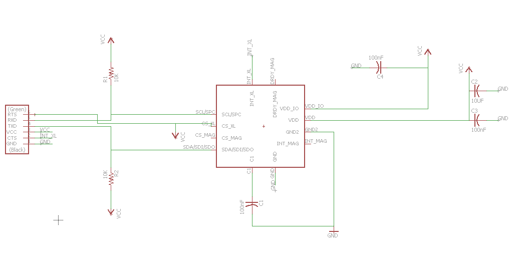
The components I used in this board are:
-The accelerometer: LSM303C ( x 1)

-10K resistors: RES-US1206FAB (RES-US) R1206FAB ( x 2)

-FTDI-SMD-HEADER 1X06SMD ( x 1)

-100nF capacitors: CAP-US1206FAB (CAP-US) C1206FAB ( x 3)

-10UF capacitor: CAP-US1206FAB (CAP-US) C1206FAB ( x 1)
I am aware that human persons write the bill of materials in a totally different way, but I am not comfortable with that just yet. Just let me do my thing, kk? Thx.
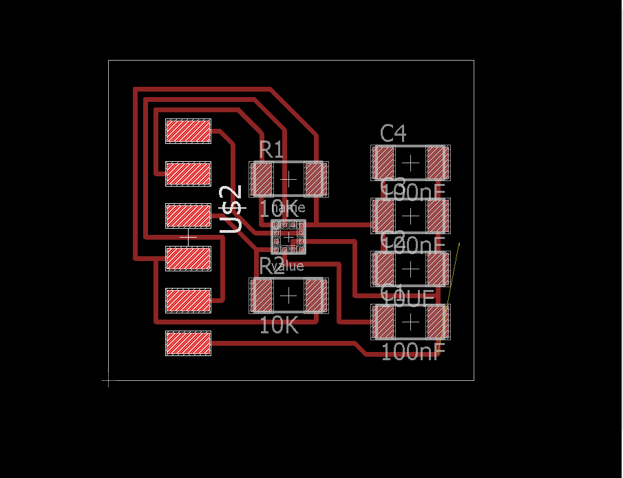
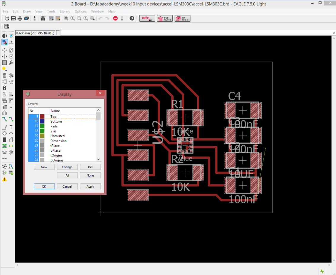
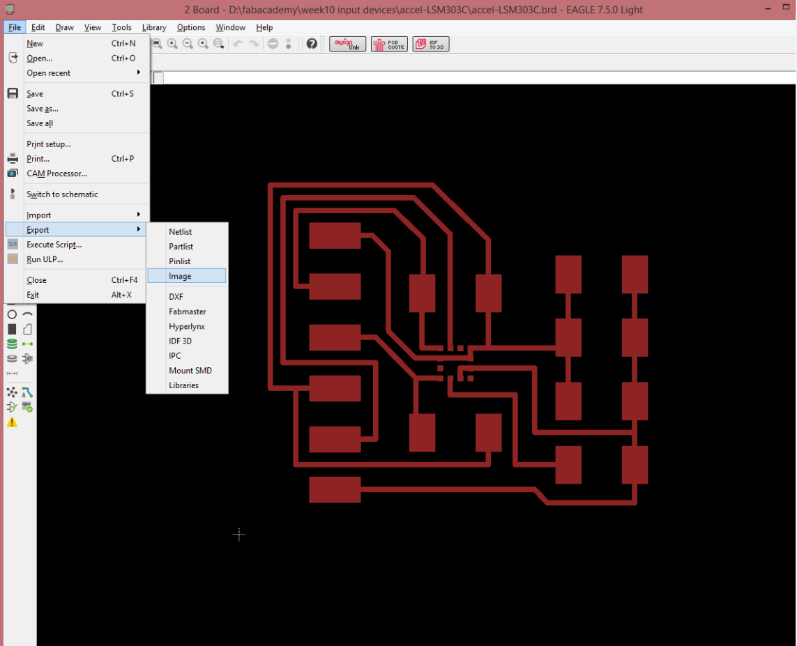
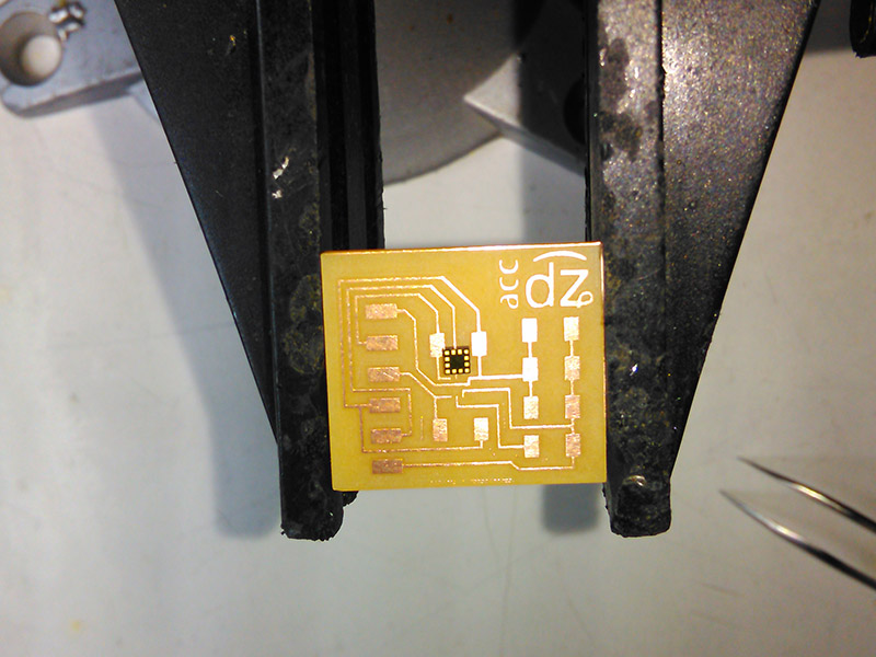
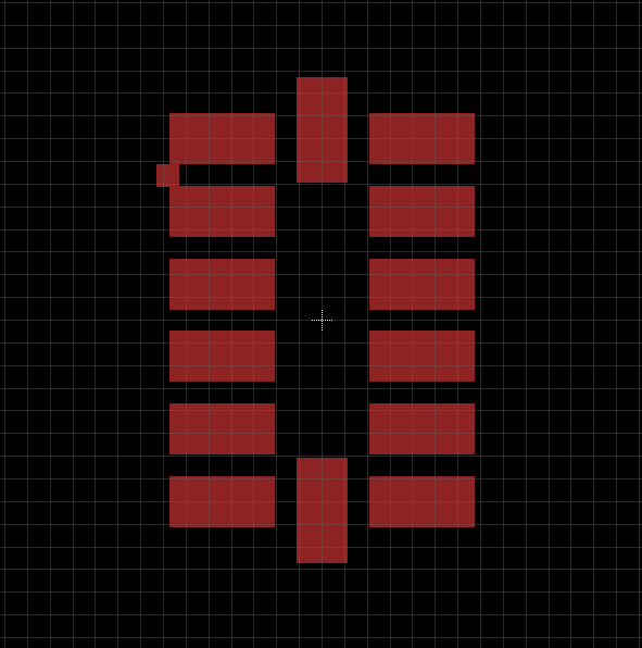
The next step is to actually have the image to use for the milling. I will go through the steps here quickly because I recently noticed that I hadn't done that in the actual week I should have. So here that goes.
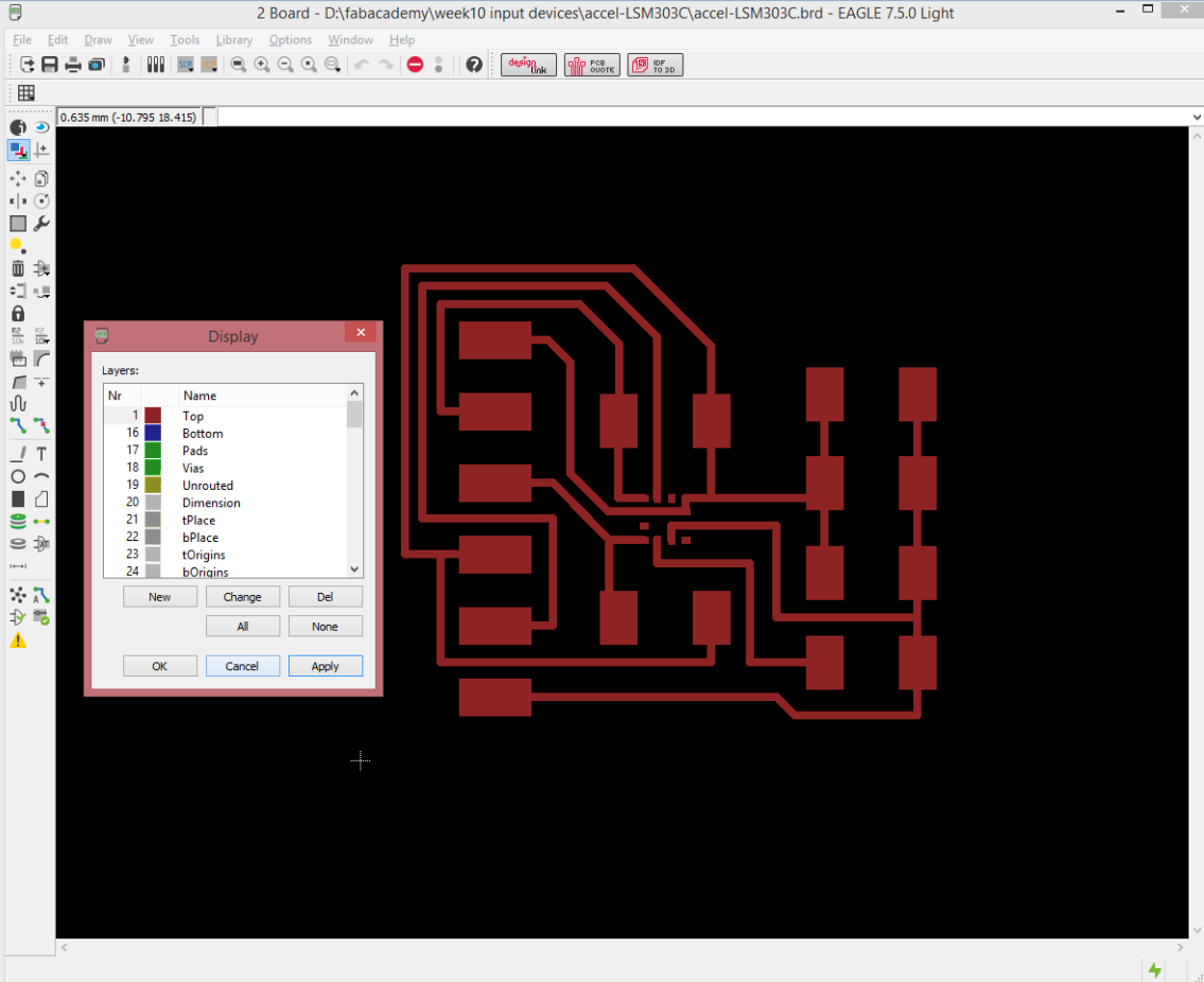
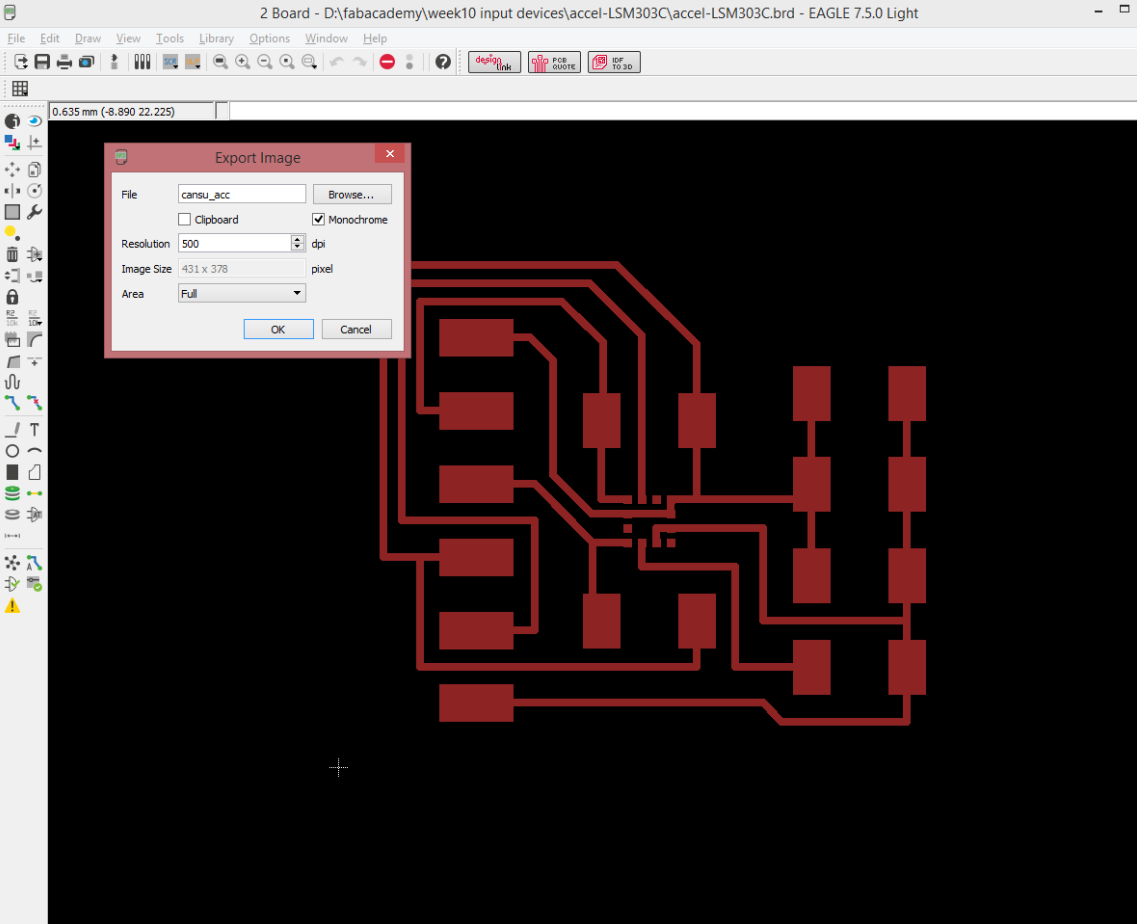
The traces, as you can see, are already tiny, and the pads of the accelerometer are basically nonexistent. But that's fine. We have other problems. Don't worry about that.
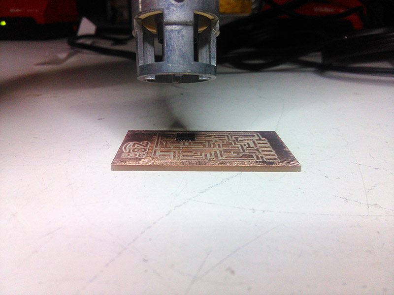
Milling the Board
OK now comes the hard and important part: actually milling this board. The reason this is particularly tricky is that the component is so tiny, the space between its pins are too big for any and every milling bit conceived by humankind, ever, in history. Then there are the traces, oh the traces.
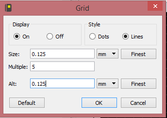
So, we are going to be using a 0.10" bit here.
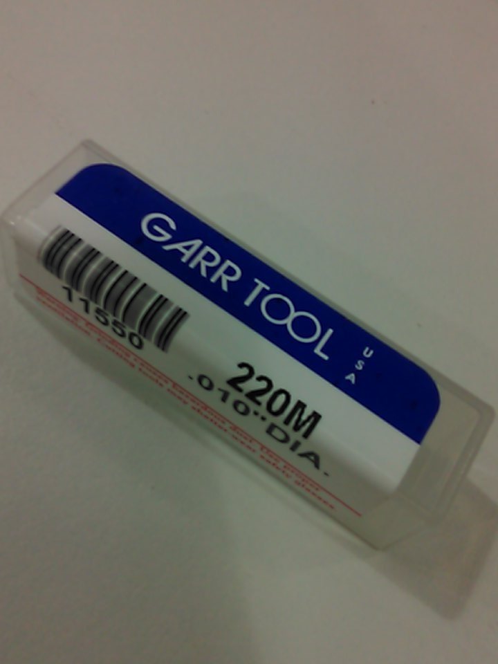
I have no idea why I didn't photograph the actual drill bit. But the thing is, it doesn't really matter because all you need to know is that it's tiny. Case in point: It took Santi and me at least one whole minute to decide if the one we had in the drawer was broken or not. It was, but still. You can usually tell when a drill bit is broken.
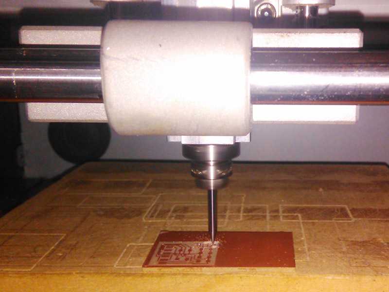
So, after you're finished being awestruck with how incredibly tiny this bit is, you realize that yes, you are indeed going to break it if you aren't careful. Actually, care isn't enough. You have to go where no PCB-miller has gone before (yes they have, whaddayatalkingabout?) and make a roughing pass.
This part is pretty straightforward and it is exact same thing we have already done in the previous weeks of Electronics Production and Electronics Design so I won't go through that again. But, one thing to remember is to set the number of offsets to -1, which will make the machine take out all the extra coppper, and that is important because we don't want our *very* fragile 0.10" bit to encounter any more resistance than it can handle, which is a really tiny bit of resistance. In the feeling of keeping the tradition alive, I forgot to take a screenshot of this exact phase of the project. You'll live. Don't look at me that way. I did take screenshots on the actual important stuff.
After the roughing pass with the 1/64" drill bit is done, you VERY CAREFULLY replace the bit with the 0.10" one. And I mean careful. I mean not dropping the bit to adjust the Z careful. Then you take your file and make some adjustments with the settings of the Roland SRM-20 in the fab modules.
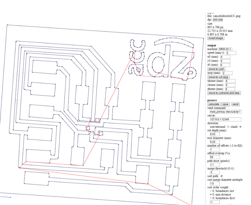
The important part in these settings is first the cut depth: I used a 0.03 mm cut depth for this. I actually prepared seperate files of 0.03, 0.06 and 0.09 mm cut depths to use as necessary to remove all the copper, but just the 0.03 and the 0.06 were enough and I didn't end up using the 0.09 mm depth file.
The second important setting is the tool diameter. I used the smallest bit available, but it was still not small enough and the paths wouldn't show up in the preview correctly. In order to make the fab modules actually draw the path I wanted, I adjusted the size of the drill bit with the "Tool Diameter" setting. When you first choose the 0.10" traces option from the menu, it gives you a 0.254 mm diameter. I lowered the diameter gradually and found that this (0.20 mm) was when the toolpaths actually resembled what I wanted. In his documentation, Gabriel says he managed with 0.22 mm, but no sir, that wasn't the case for me.
After adjusting the cut depth and the tool diameter and in fact seeing the desired paths, you can hit calculate. One thing I would like to stress in for board is to make ABSOLUTELY SURE that you didn't accidentally hit the dreaded "move to xy0 zjog" or "move to xyzhome and stop" buttons which are located, so conveniently, like minus one pixel below a text box you actually need to adjust settings in. Because that risks breaking the mill. Yes even though we milled the minus one out of the rest of the copper. The bit is *that* tiny.
If I have scared you enough with the 0.10" bit, I have done my job. Then you can calculate and save the code and run the code with the machine as planned - NOT! Of course not. You thought you could get away with it, didn't you? No. You have to run the machine at 20% speed, any faster will break the bit. OK maybe 30% won't break it, but saving minutes isn't worth breaking the mill. Did I mention that you can very easily break this bit? Oh, OK, just to be sure.

Surface Soldering the Components
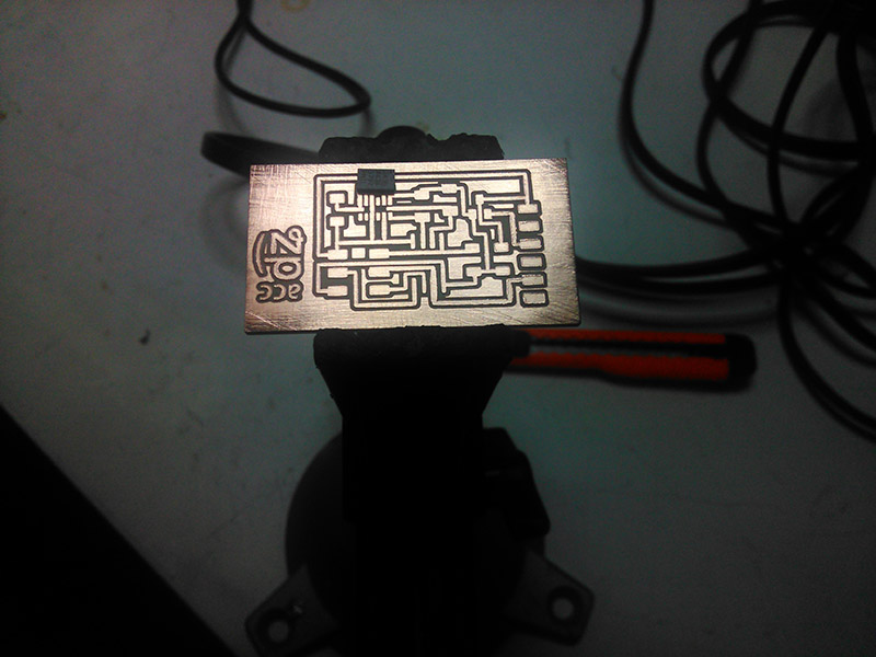
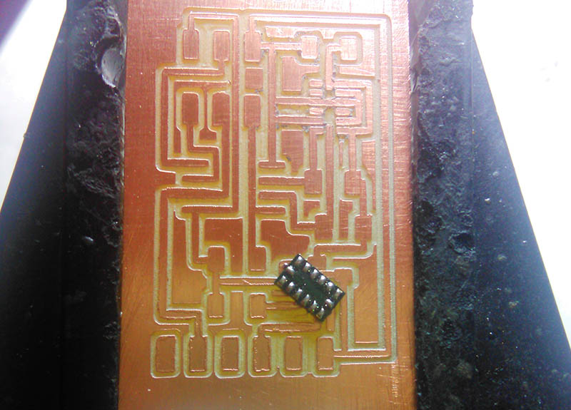
Congratulations, you have milled the tiniest of tiny traces successfully. Go get a milkshake. You will need it when you see the actual size of the "pads" you have to solder. There are no pads. NO. PADS. The component is that tiny.
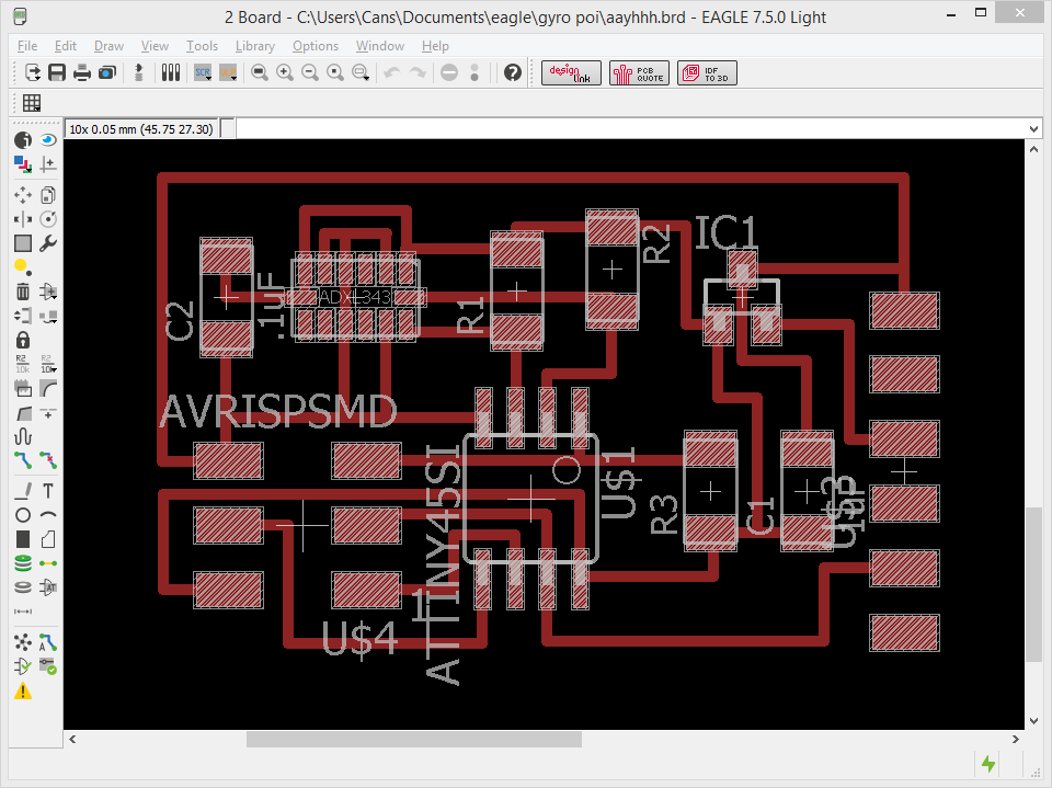
The width of the board is 27 mm. OH WELL, TOUGH LUCK CANSU, NOBODY TOLD YOU TO PICK THE TINIEST AND HARDEST SENSOR TO DO. Aaaaanyways...
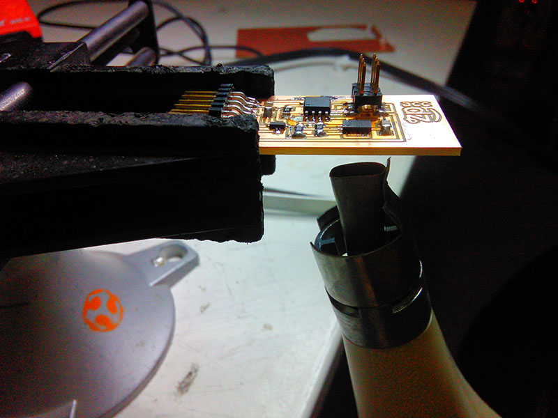
This is obvious but I want to write it down so I won't forget: The component has a dot on the top left corner, it is supposed to be on the top left in this orientation of the board. Again, in this orientation, both sides of the bottom right corner have the ground pins.
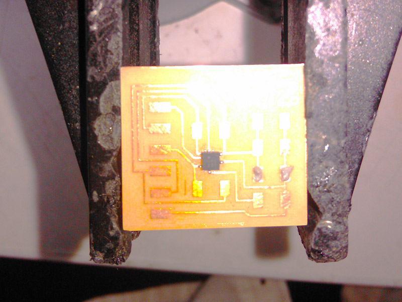
The above photograph actually shows some solder paste action. This is very basic stuff, so I'll just embed a very basic video for it. The action starts around minute 7 because of course it does.
Put some solder paste on the traces, place the component correctly and if possible perfectly so you don't move it around, and then hit it with the heat gun. Then it's done.
...Unless you have the most insane component in the known universe and beyond.
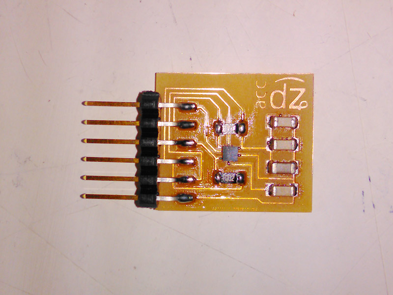
After the accelerometer was in place, I soldered the rest of the components, which frankly was the easiest solder I have ever done because the components are huge (Look how my perception has shifted now. Pity.)
As usual, I checked the connections with a potentiometer. But that is a redundant exercise in this case, because there are no connections that can actually be checked in this way, the only connections you actually need checked are the accelerometer's, but you can't because the universe hates you and you want to measure acceleration on 3 axes. FOR SHAME, MADAM. FOR. SHAME.
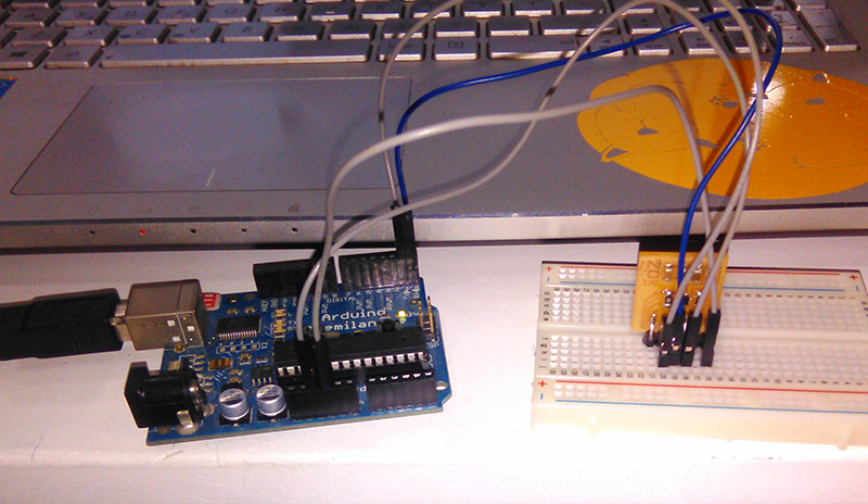
Time to check. The only way you can check this board is by plugging it in. So I did.
Preparing the Board For Use
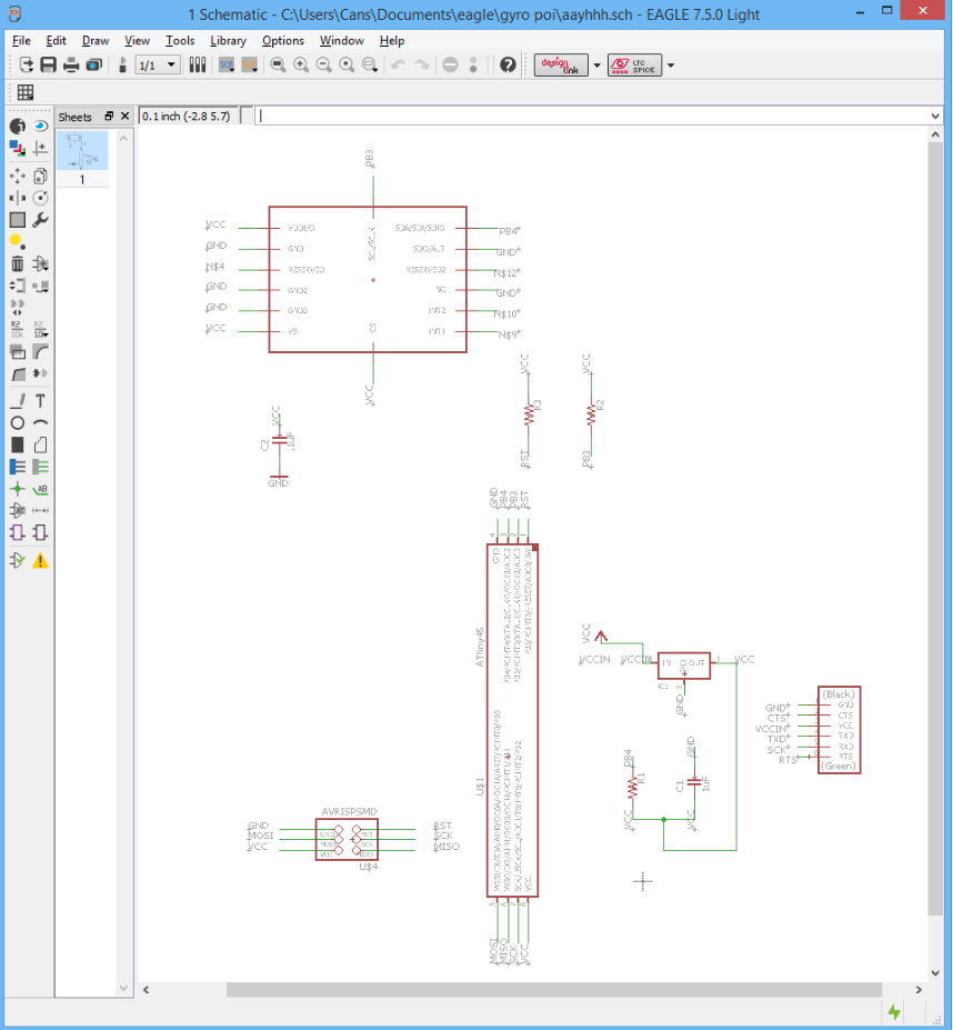
This is mostly so I don't forget: As the schematic shows, the pins go to (from right to left in this image above)
1st pin: GND,
2nd pin: (empty),
3rd pin: VCC/5V,
4th pin: RX,
5th pin: TX,
6th pin: (empty)
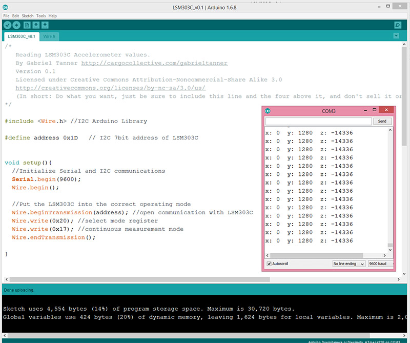
I downloaded the Wire.h library to use with Gabriel's example code to test the accelerometer. If the board was working, the x, y and z values would differ when I moved the board. But as you can see below, nothing is happening and this is just the values the Arduino picks up from the depths of the ether because we as the Fab Lab Barcelona people have no idea why it gives these values. Seriously, I asked around. Nope. No clue. Nada.
I will include this in the end in the .rar file, but in case something happens to that file, here is the code I uploaded to the Arduino:
/*
Reading LSM303C Accelerometer values.
By Gabriel Tanner http://cargocollective.com/gabrieltanner Version 0.1
Licensed under Creative Commons Attribution-Noncommercial-Share Alike 3.0
http://creativecommons.org/licenses/by-nc-sa/3.0/us/
(In short: Do what you want, just be sure to include this line and
the four above it, and don't sell it or use it in anything you sell
without contacting me.)
*/
#include//I2C Arduino Library
#define address 0x1D // I2C 7bit address of LSM303C
void setup(){
//Initialize Serial and I2C communications
Serial.begin(9600);
Wire.begin();
//Put the LSM303C into the correct operating mode
Wire.beginTransmission(address); //open communication with LSM303C
Wire.write(0x20); //select mode register
Wire.write(0x17); //continuous measurement mode
Wire.endTransmission();
}
void loop(){
int x,y,z; //triple axis data
//Tell the LSM303C where to begin reading data
Wire.beginTransmission(address);
Wire.write(0x28); //select register X_LOW register
Wire.endTransmission();
//Read data from each axis, 2 registers per axis
Wire.requestFrom(address, 6);
if(6<=Wire.available()){
x |= Wire.read(); //X lsb
x = Wire.read()<<8; //X hsb
y |= Wire.read(); //Y lsb
y = Wire.read()<<8; //Y msb
z |= Wire.read(); //Z lsb
z = Wire.read()<<8; //Z msb
}
//Print out values of each axis
Serial.print("x: ");
Serial.print(x);
Serial.print(" y: ");
Serial.print(y);
Serial.print(" z: ");
Serial.println(z);
delay(50);
}
Actually Making the Board Work
Frankly, after this, me and Ferdi went back to the soldering station and tried for a couple hours more to solder it correctly. I did end up with a bent board, which is nice in its own way I guess, but not useful in this situation. Sad day for all of us. This is my first actual big fail in the Academy.
I will keep working on this, because I want to use this input for a nice output week side project and my final project. We discussed this with Ferdi, we will either a) make another board that has some different connections and try another technique for soldering, or b) get another 3D accelerometer that is not insanely tiny so I can keep my sanity and have nice projects. Frankly, I'm rooting for option b because I don't think I want to deal with such an unnecessarily hard task when there are legitimately useful hard tasks to tackle during the remaining time in the Academy.
Conclusions
I have to say I was getting pretty confident with my soldering skills, but this week has been a humbling one. If I could make it work, I would draw different conclusions but now I can only say that it is important to choose your projects according to your skill level. But the thing is, when I actually make this work, the end result will be worth the frustration.
You can find the files that produced this spectacular failure below.
Redesigning the Board
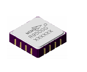
After we all failed with the first accelerometer, Ferdi offered to order another accelerometer that is not insanely tiny so I could try it again. I am using this sensor for my final project, so it sort of has to work. This is the second attempt in making a board with an accelerometer that actually works. Here we go.
The accelerometer I'm using is this one. As you can see from the data sheet, this one is huge compared to the first one.
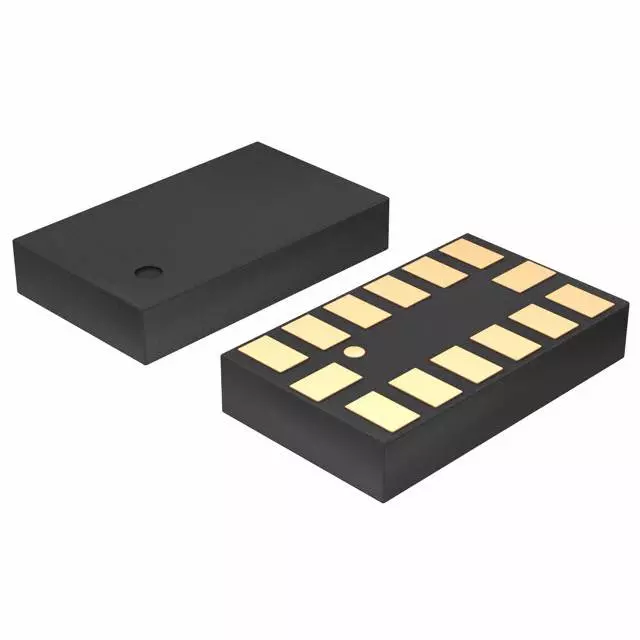
Luckily, this one also happens to be the one in the inventory that was nixed in favor of the tiny one. So, we have example boards to work from! And, in fact, I actually did work on them, it was a mistake at the time, but still.
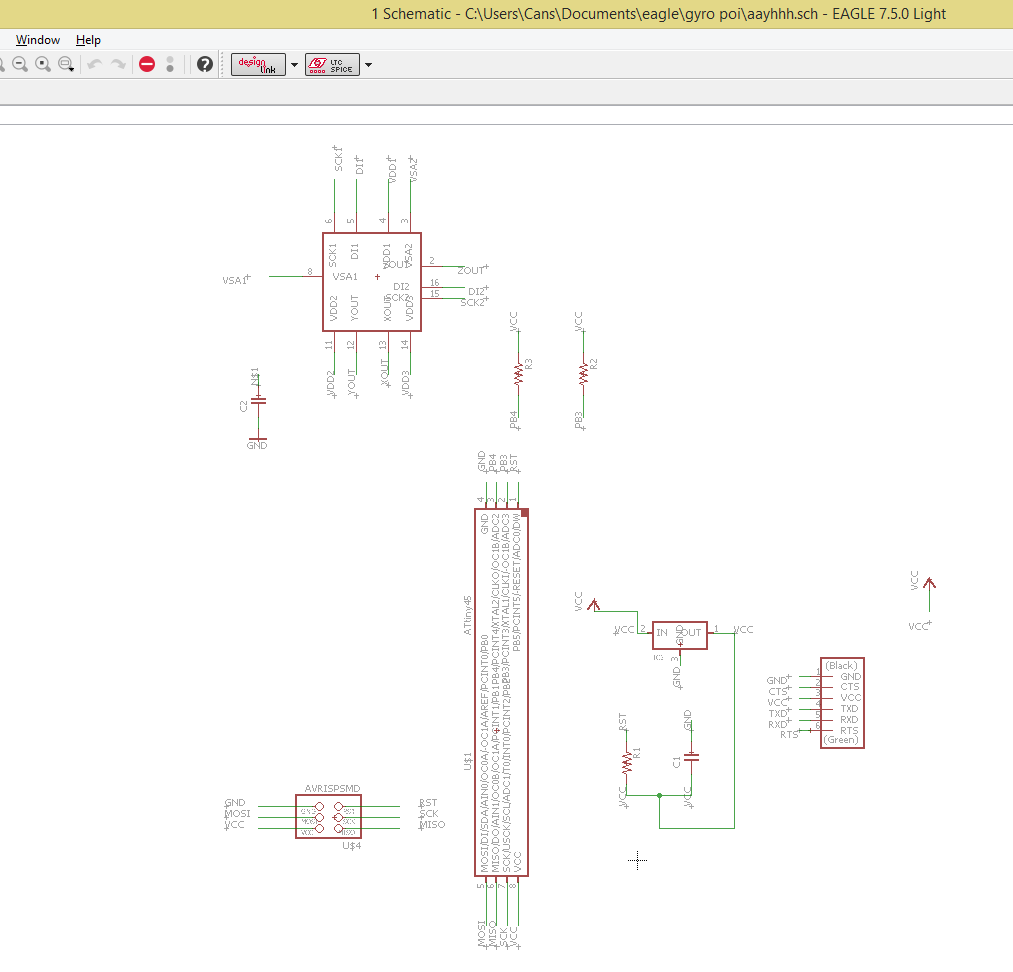
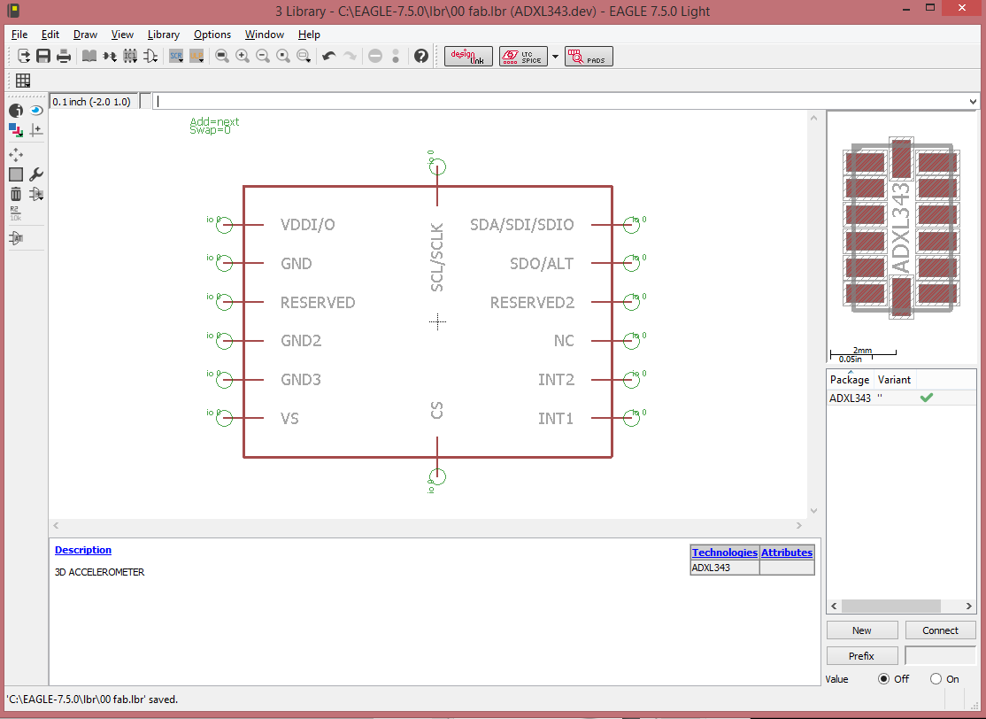
I had stopped working on the file before I realized that the accelerometer I was using in there was this one, and not actually the ADXL343, this one is in the fab library, but isn't in the inventory.
I searched online if I could find an ADXL343 to use in Eagle, but of course with my luck it was impossible. So I made one myself, following this tutorial.
Then I proceeded as normal and used the same components in Neil's board and made it again.
Resoldering the Components
For the tiny pads of the accelerometer, this step gets important. And, again, the only thing you can actually check is whether your solderwork shorted something, but if you didn't short but failed to connect the pads in another innovative way, you can maybe guess at things by the process of elimination and that's it. So, pay attention.
I didn't end up using it, but I did make a solder mask with the vinyl cutter. To do it, you have to find the layer in Eagle with the actual pads and nothing else. Usually we turn this off, and by default it doesn't have a solid fill, it's one of the hatched ones.
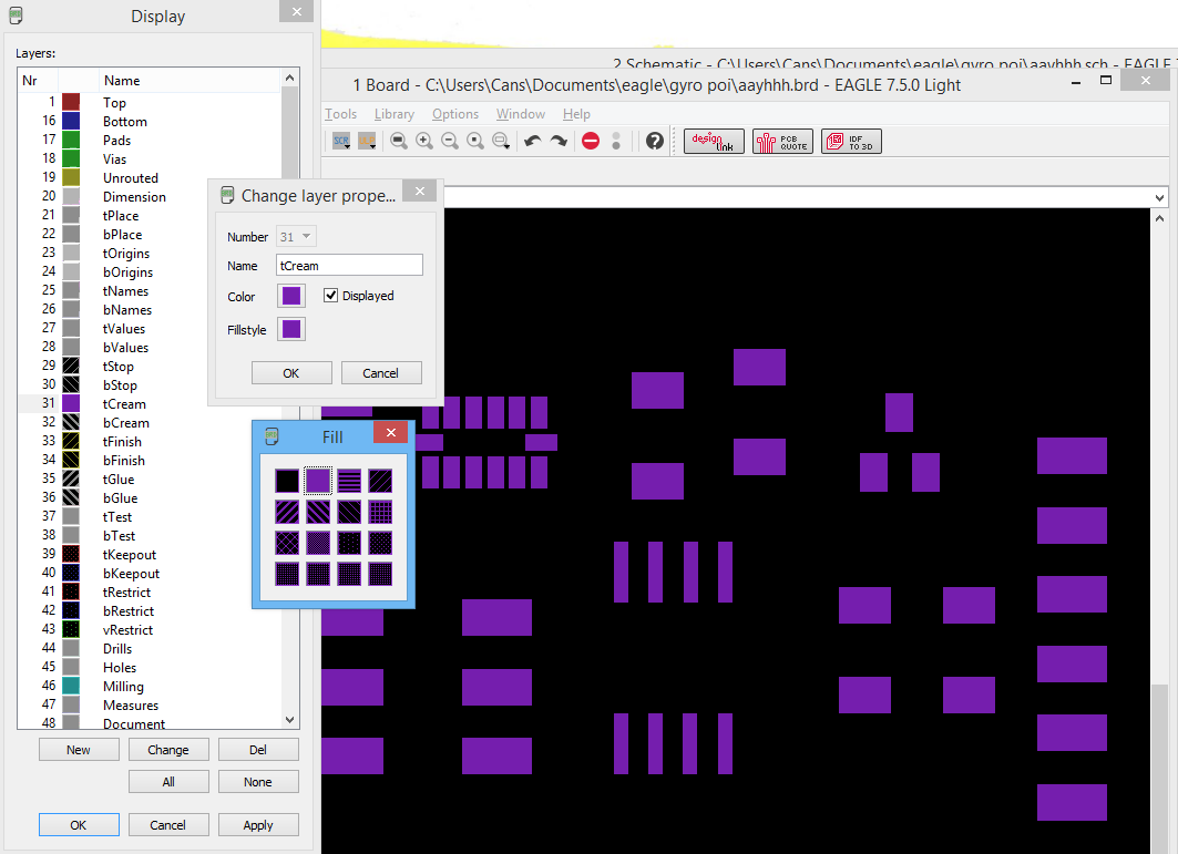
With only the tCream layer (which, come to think of it, probably means "solder cream") active, you export as usual, and then feed the resulting PNG to the vinyl cutter. Then you place this cut out very carefully on your board, lined up with the actual pads. Spread solder paste, remove the vinyl, place components and heat with the heat gun. I don't have pictures for this process, because I didn't actually end up doing it, but this is how it's done.
I did use solder paste with the accelerometer though. I have found putting the paste on the board and heating and yadda yadda yadda, the usual technique everybody talks about doesn't work for me. Instead, I put a tiny bit of solder paste directly onto the component's pads, heat it just for a second with the heat gun (or even sometimes the tip of the soldering iron is enough).
You can then use the very tip of the iron to clean up any pads that might have ended up connected. But usually you won't have to, because the paste cleans up nice on its own.
Later on, what you need to do is to place the component and heat again to fuse with the board.
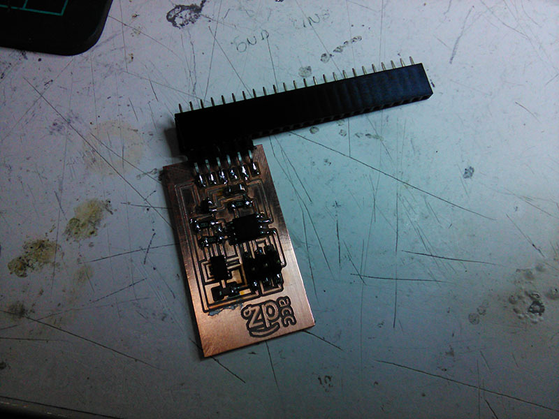
The rest of the board is insanely easy to solder in comparison, so no details there. Although I did use a trick I'm very proud to have thought of all on my own, which is to use female headers to hold the male FTDI header in place when soldering.
Actually Making It Work
After the soldering, I started to try and program the board. I failed miserably, of course.
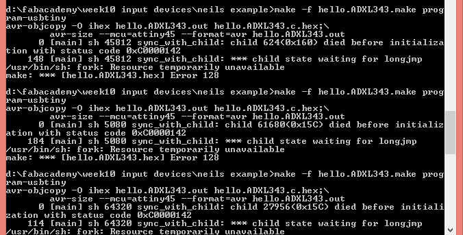
OK, this shows an error with the board, which is of course the soldering. In fact, I think I shorted the power but this is unconfirmed. I went back to fix this. And, I will admit now that I just lied to you above, because the first time I soldered the accelerometer by heating from above, and I had to push it down, and I ended up shorting several pins of the ATTiny. Then I wised up and desoldered and resoldered by heating from below. So, now you know the most important thing about me: If I speak in a very confident way about how to do something, it means I tried it before and I failed and I know for a fact that the other approach you just mentioned fails. It's never by reading or watching other people fail that I learn. I fail myself.
As you will remember, my notebook hates the make command. That is still the case, and I can't program boards on my own. This week I think I asked Santi's help, and I also think he forgot to send me the screenshots, so I have no proof of me programming this. Anyways, at some point I did get it working with Neil's example python script.
Before that point, we tried and tried with Ferdi to no avail.
Input Devices - Accelerometer First Test from cansu pekoz on Vimeo.
This is still a badly soldered board. I have no idea what the timeline was anymore, it failed, I fixed it, it failed again, I fixed it again, and I'm really not sure when these happened. I should better organize my archive.
And then I actually got it working. You can see the first results from the board in the video below.
Input Devices - Accelerometer Test from cansu pekoz on Vimeo.
Conclusions
Well, I'm tired.