Week 6: Electronics Design
The Recitation
The Lecture
3D Scanning and Printing review and Electronics Design lecture by Neil Gershenfeld can be found here
The Assignment
Redrawing the Echo Hello World board.
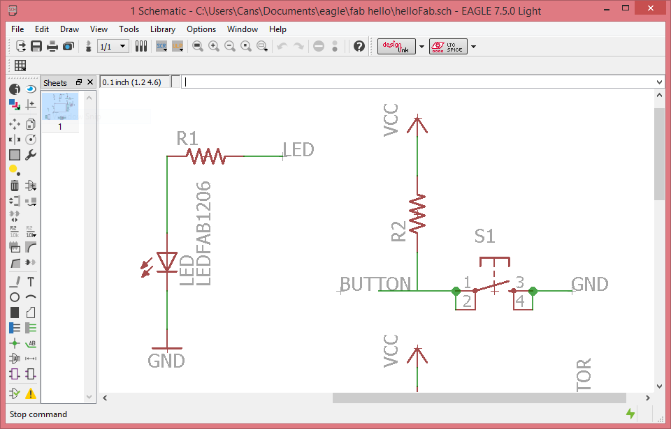
-Drawing the schematic: Adding at least a button and LED

-Making the board
Drawing the Schematic
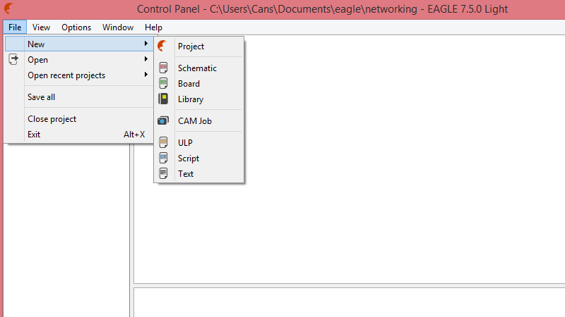
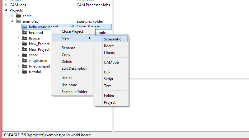
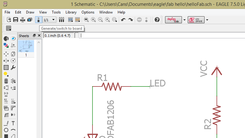
I am going to be using our beloved software Eagle and Neil's example board and add a LED and a button myself.

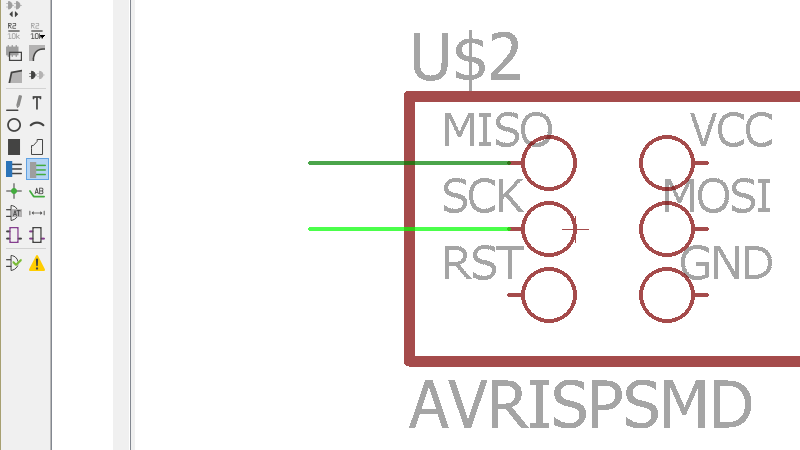
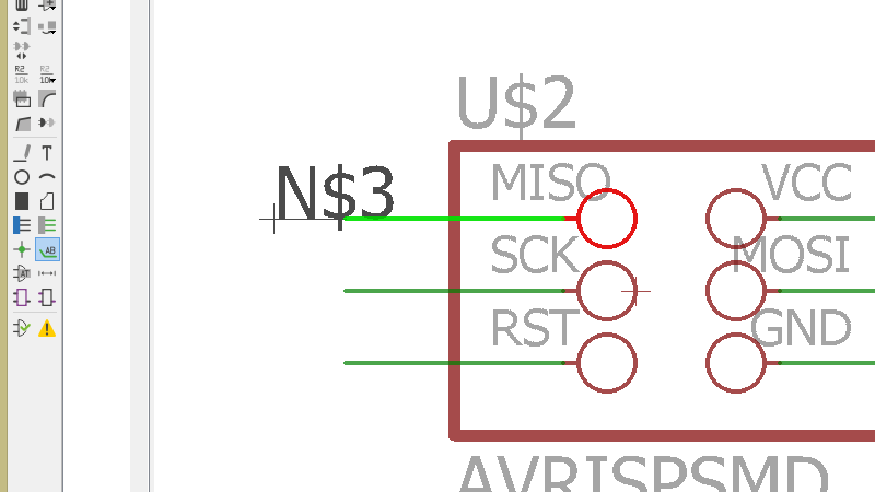
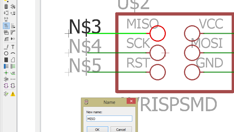
One way to connect things is literally taking the net tool and drawing lines between the relevant pins. Another is to add bits of "wire" to pins, and naming them.
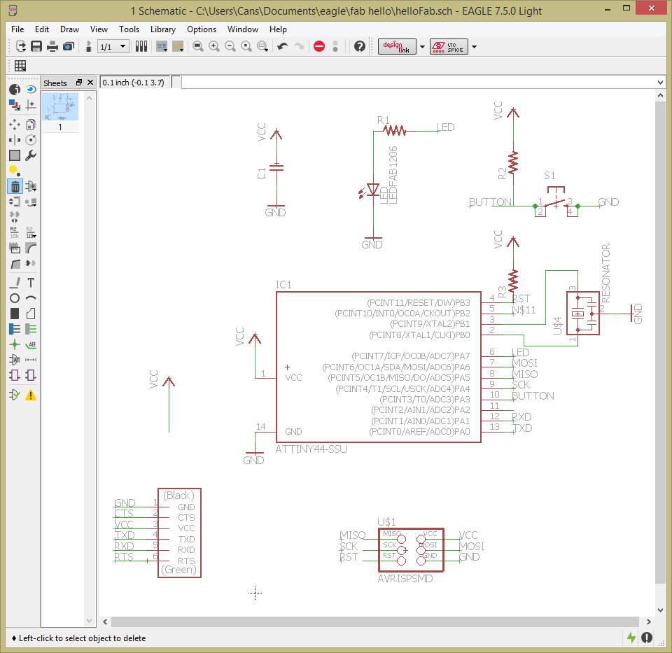
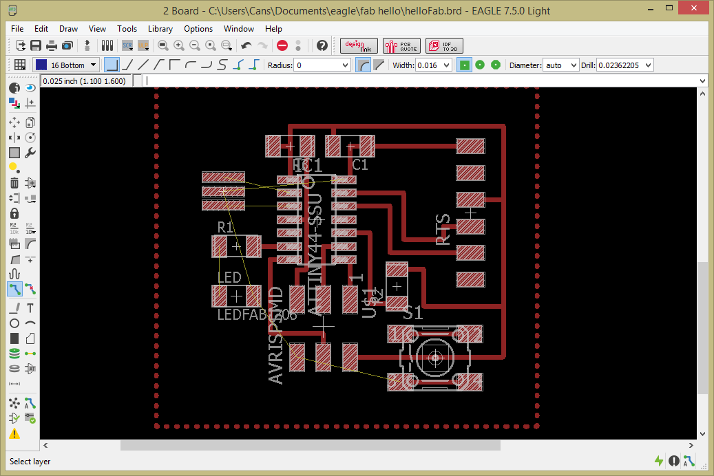
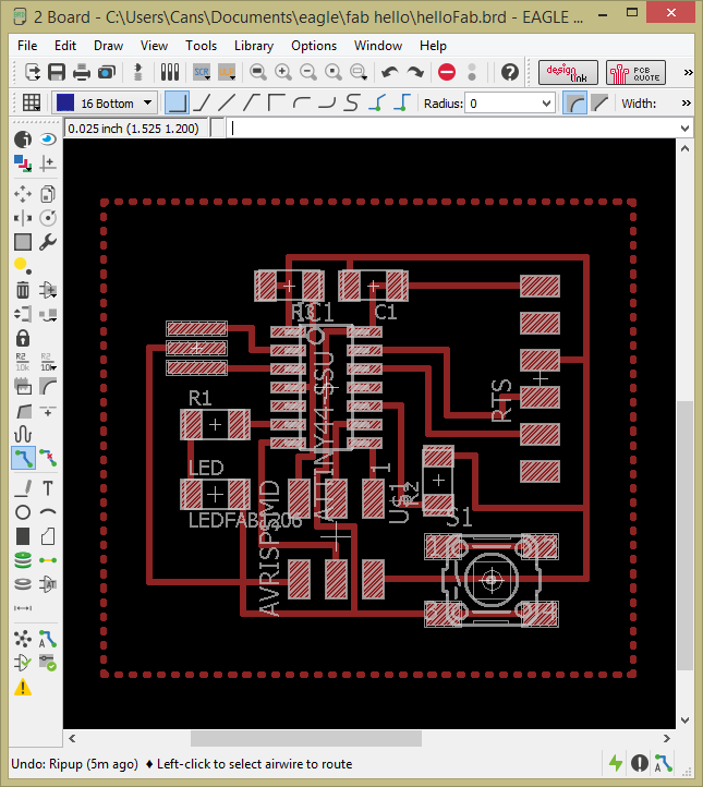
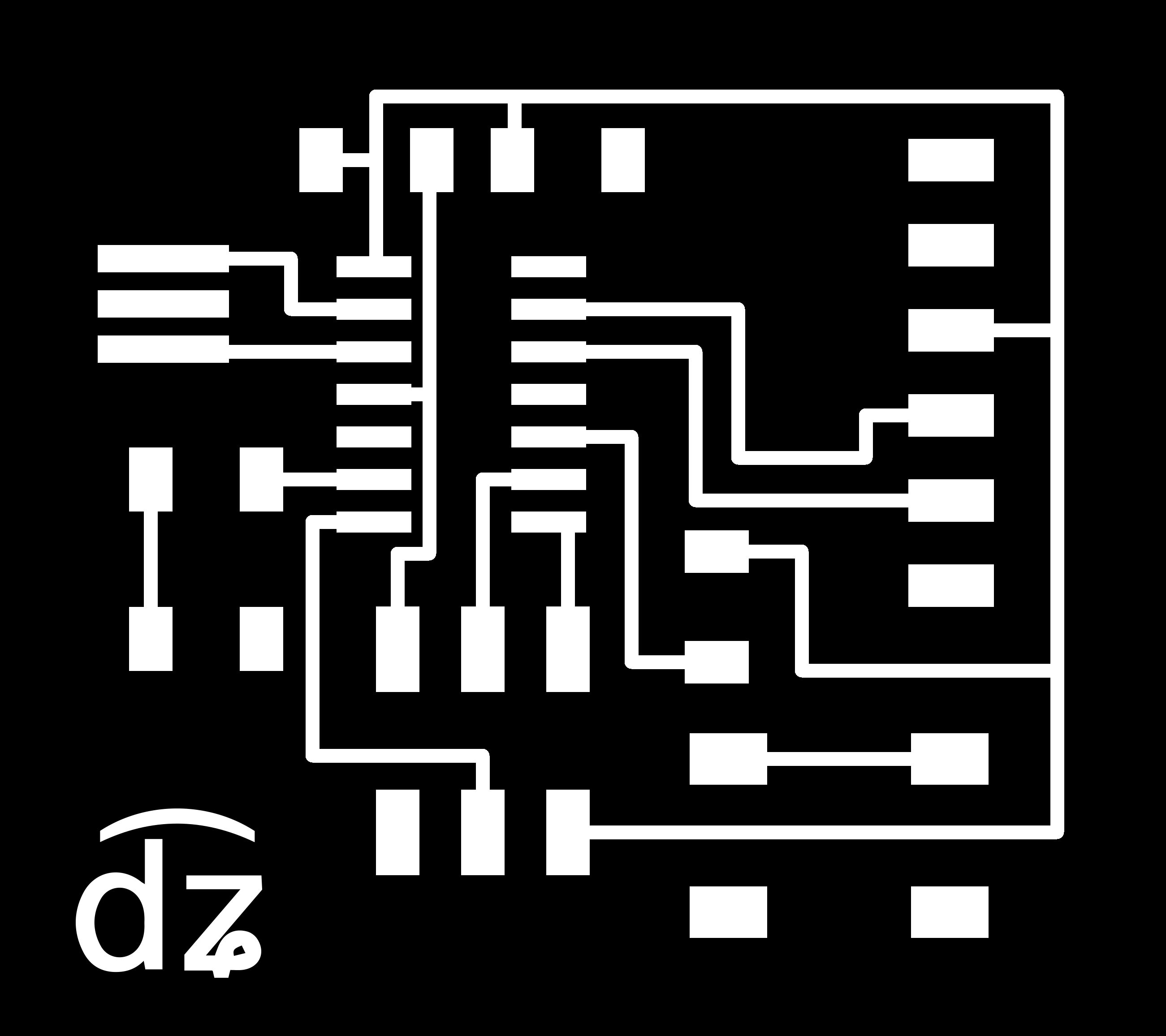
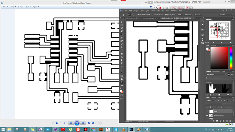
When you're generating the board for the first time, the components show up in a jumble on the lower left hand corner. I forgot to take a screenshot of that exact moment. Then you need to drag them to the desired places and you can start routing.


Somehow somebody in the lab (no idea who, or when, or why, really) gave me the idea to do a ground plane for the board. Remember when we are milling the boards we put in an offset of 4 and the rest of the copper stays in place? When you use a ground plane, the pads that are connected to the ground are connected to the rest of the copper too, so you have one giant funnily shaped "pad", in a sense. According to Wikipedia, this "serves as the return path for current from many different components", whatever that means. You can route easier and for radio frequency and digital boards, and apparently it helps reduce electrical noise and interference. OK, good to know. Anyways, so I did look into using a ground plane. Here is a tutorial on doing it in (an earlier version of) Eagle:
In the end, I decided against using a ground plane on several reasons: 1-Not a "digital board", or RF. 2-Not doing a multi-layer PCB or a PCB that is insanely complicated that I need to save routing space. 3-I actually don't know enough right now to understand if what I'm doing is fine or not, so I wouldn't be able to troubleshoot.
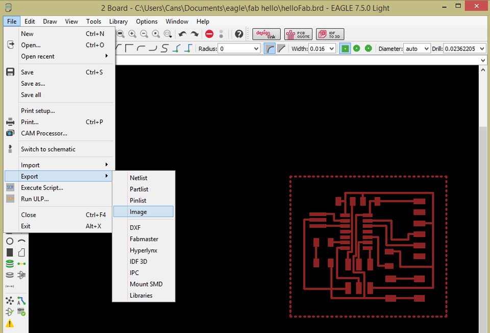
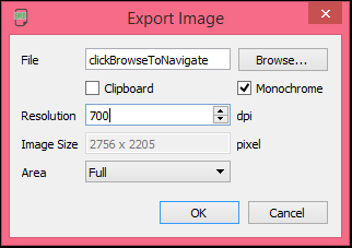
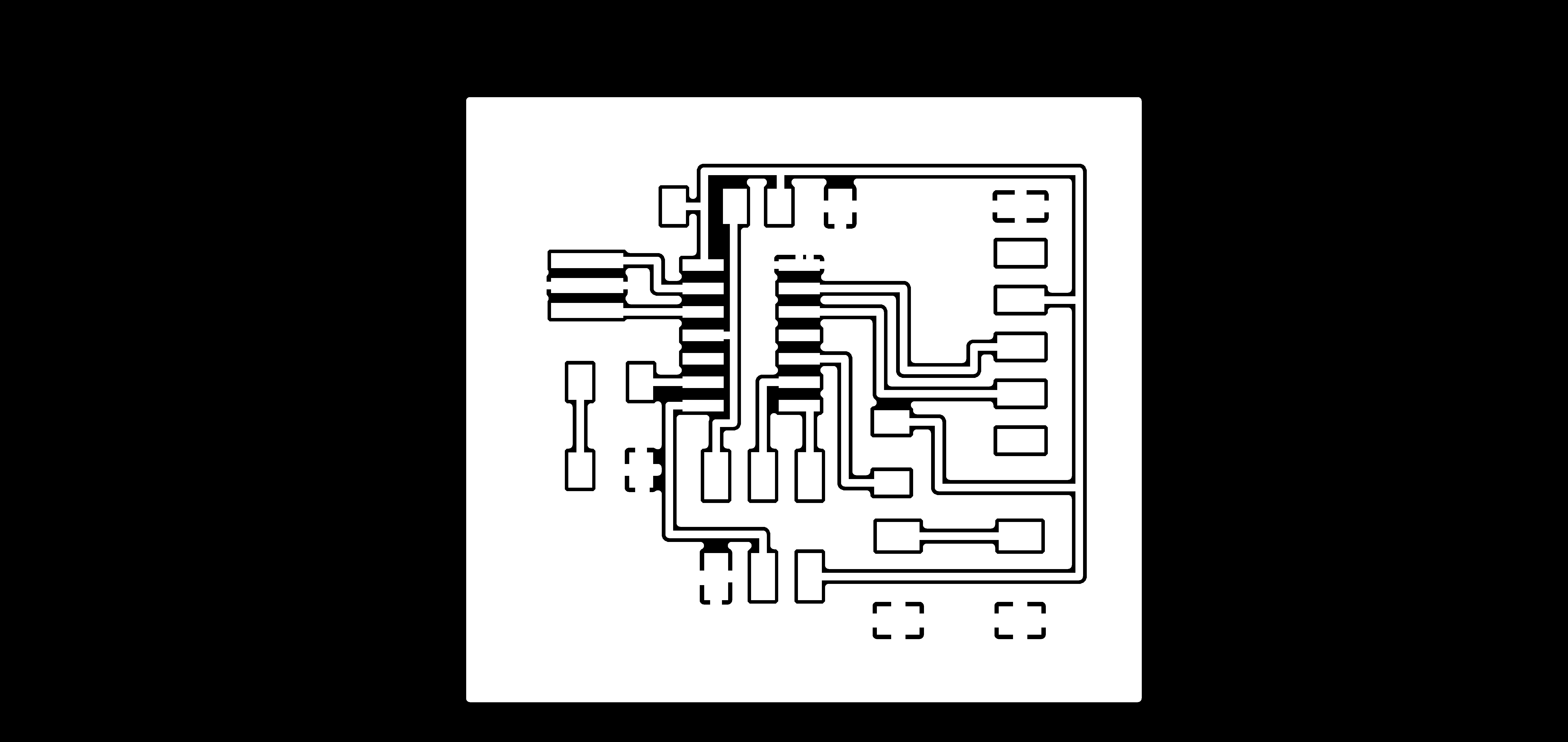
OK, no ground plane. Time to prep the outline file.

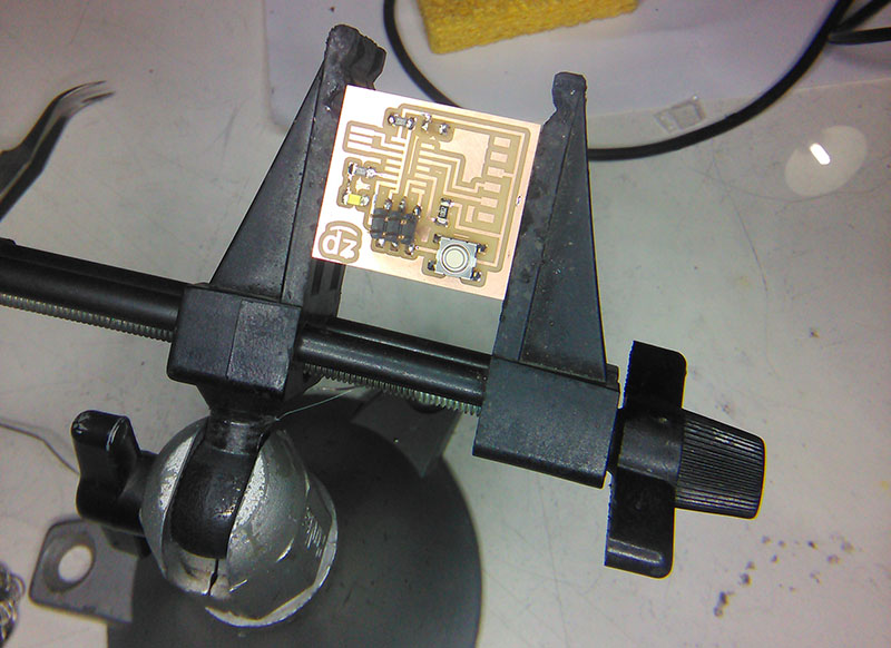
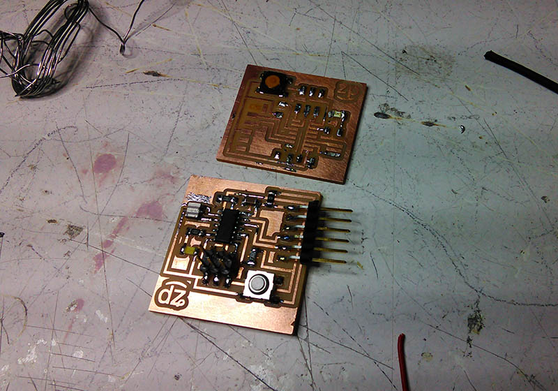
Making the Board
The border is actually supposed to be 1.6 mm for the 1/32" bit we're using in the lab to cut the boards out, but I have found that basically almost any size works. Go crazy, you crazy diamond.
The actual steps to cut and clean and stuff the board are the same as Electronics Production week. With one distinction I learned this week: The BOM.

That is all for this week. I should apparently write "OMG I will *definitely* work on this and that and the other thing" here, everybody semes to be doing that, but basically I am happy to ask the basic questions for the things I'm learning. [July Update: Nobody actually ever worked on anything they claimed to work on in the future hahah. OBVIOUSLY.]
Download Eagle FilesConclusions
This week was, again, new. It takes time to get used to Eagle, but what actually takes time is getting used to the idea of electronics and manufacturing them. It has been a nice learning experience, but I do hate soldering USB connectors, that is a fact that will never change I think[July Update: It didn't. Got easier though.]. Also, starting from this week, I actually decided to use a phonetic representation of the "C" in my name. It's easy enough to explain to people that it's "not like a Car, but like a Jar", but now I can show them as well. It's d͡ʑ, to be absolutely precise. I actually spent time on this and listened to affricate consonants a lot. I had decided not to care too deeply about people not pronouncing my name right (I am used to it, the Japanese are the only foreigners who can actually pronounce my name correct on the first try, but they have a "Ca" [otherwise known as "Ja", but that's wrong] and a "N" syllable in their language.) but I find that it actually bothers me. Your names are alien to my tongue as well. I just try to learn how you say it.
Wow, that was an unnecessarily long rant. Sorry. Anyhow... One thing I think I learned this week is, you never Auto-Route. It just doesn't work. It's there to make you feel bad. Just leave it alone and route your board. Get creative. Also, don't listen to people when they say "Ah just use the whole board as your ground, DEFFO do that." Don't do that. Unless the specific project actually requires it.
Also, I am good at soldering and I do like it very much. It's like knitting. I might have said this before. I might say this again. I love it.