Week 4: Electronics Production
The Recitation
The Lecture
Computer Controlled Cutting review and Electronics Production lecture by Neil Gershenfeld can be found here
The Assignment
Making an in-circuit programmer.
-Milling the board

-Surface soldering the components

-Preparing the board for use
Milling The Board
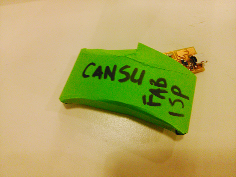
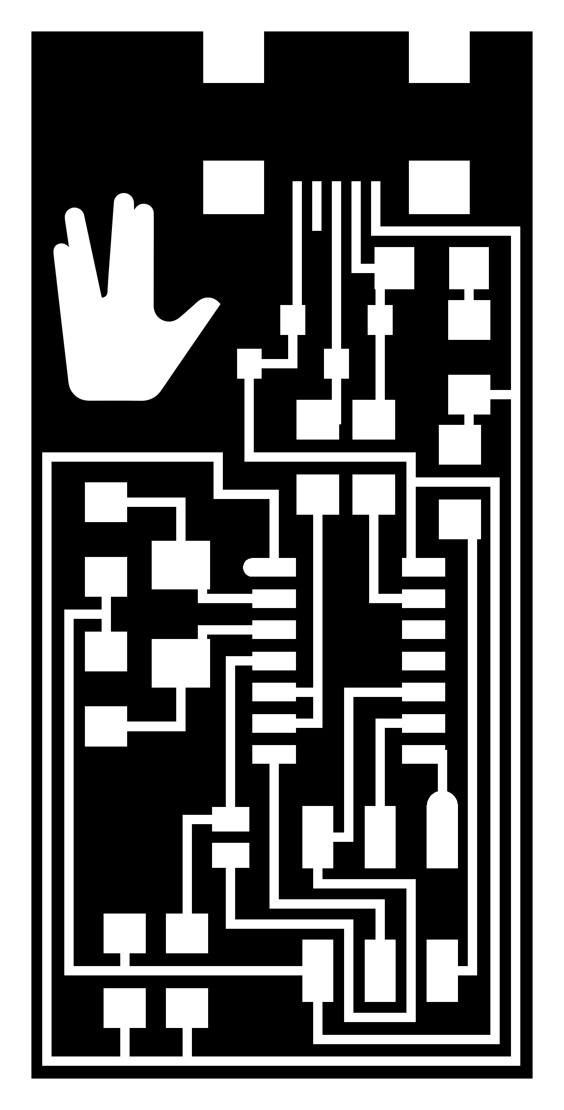
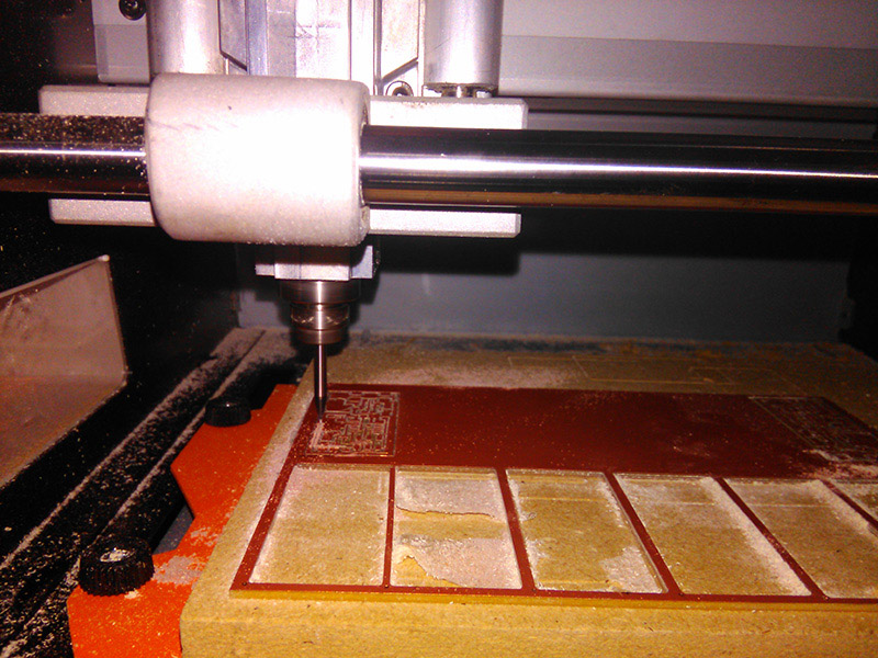
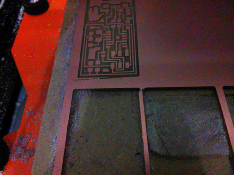
To produce a board, I used the monoFab SRM-20 and milled a piece of FR4. It was a 3-step process of first tracing the outline, then milling the traces and lastly cutting the board off the larger piece. As I was reproducing the FabISP for this assignment, I used the corresponding files to produce the g-code. I replaced the Center for Bits and Atoms logo on the corner to the Vulcan Salute in Photoshop, because why not? (Also, what if my board got lost among all the others?)

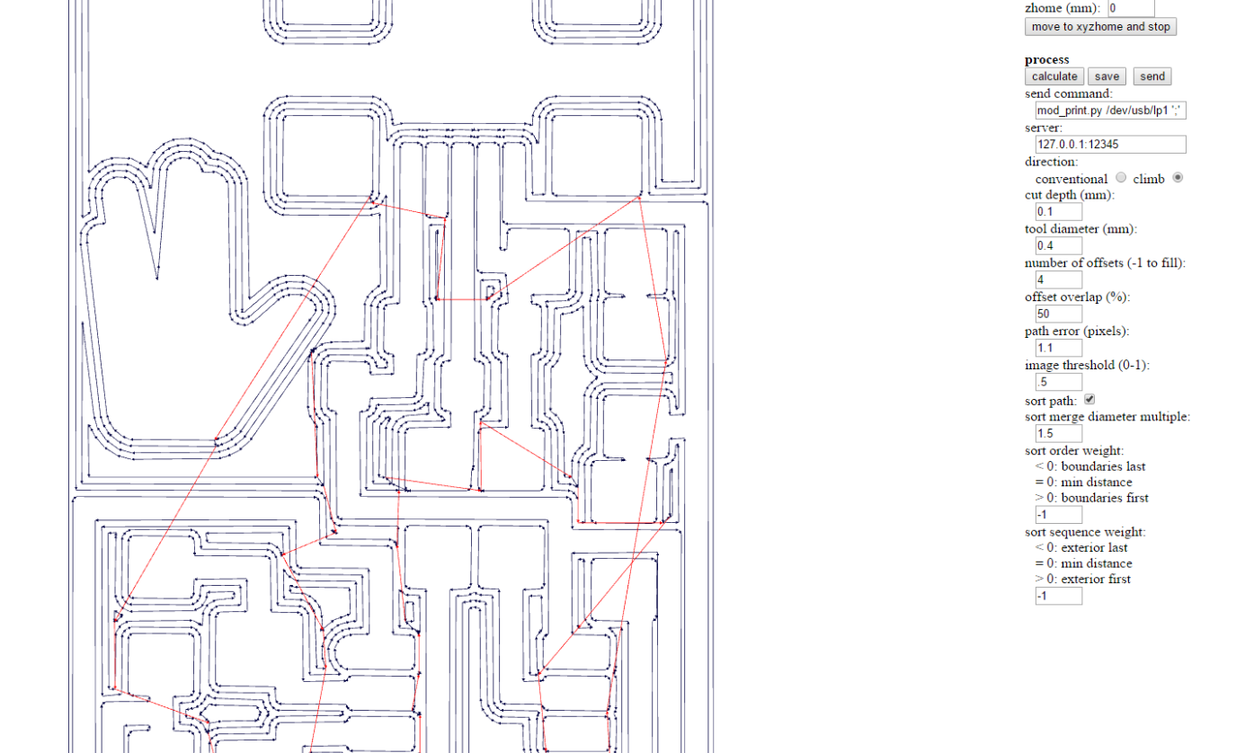
I used Fab Modules to generate the g-code. Here are the settings I used for generating the outline & trace codes, open the image in a new tab to see in full size:
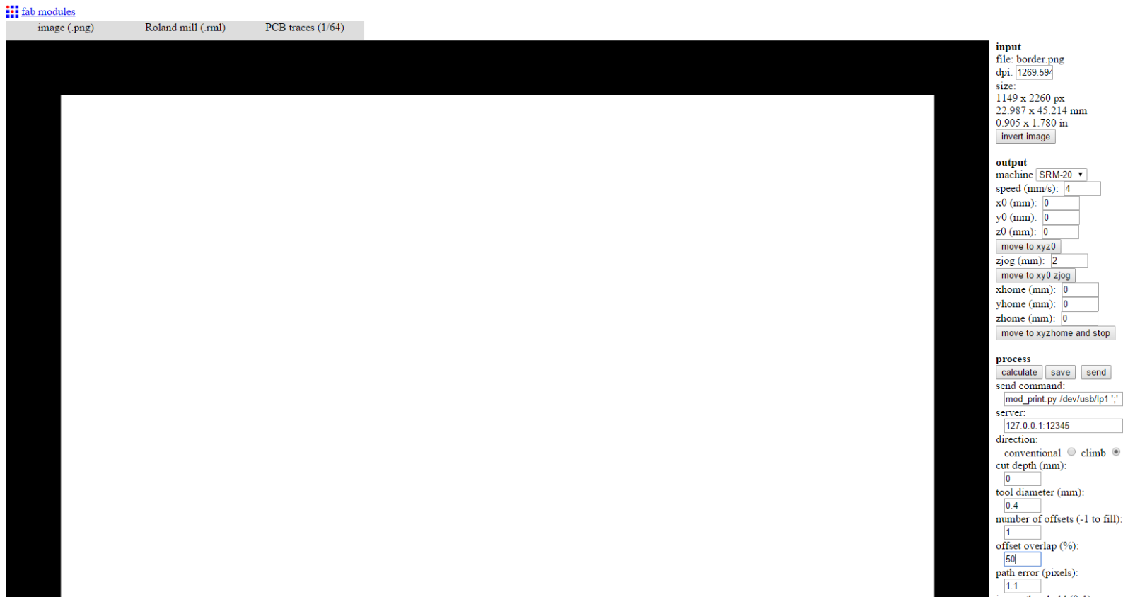
Here I actually had a problem: Even though I specified a cut depth of 0.0 mm, the tool actually cut the board superficially. I'm thinking this has something to do with a slight error in setting the zero on the machine itself. Or, the material might have been a tiny bit uneven, because I did the Z zero in the middle.
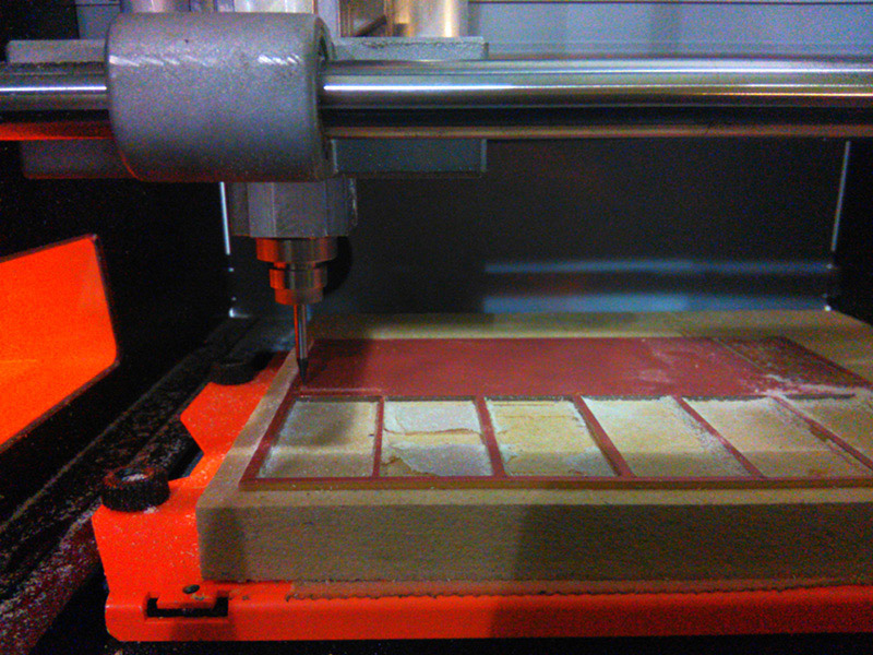
After the trial run, I milled the traces first. I used a 1/64 drill bit for this process.This went fairly smoothly I should say. There are some bits that I would have liked to see removed, but 4 offsets are enough for clearance and any more wouldn't justify the extra time spent working the machine.
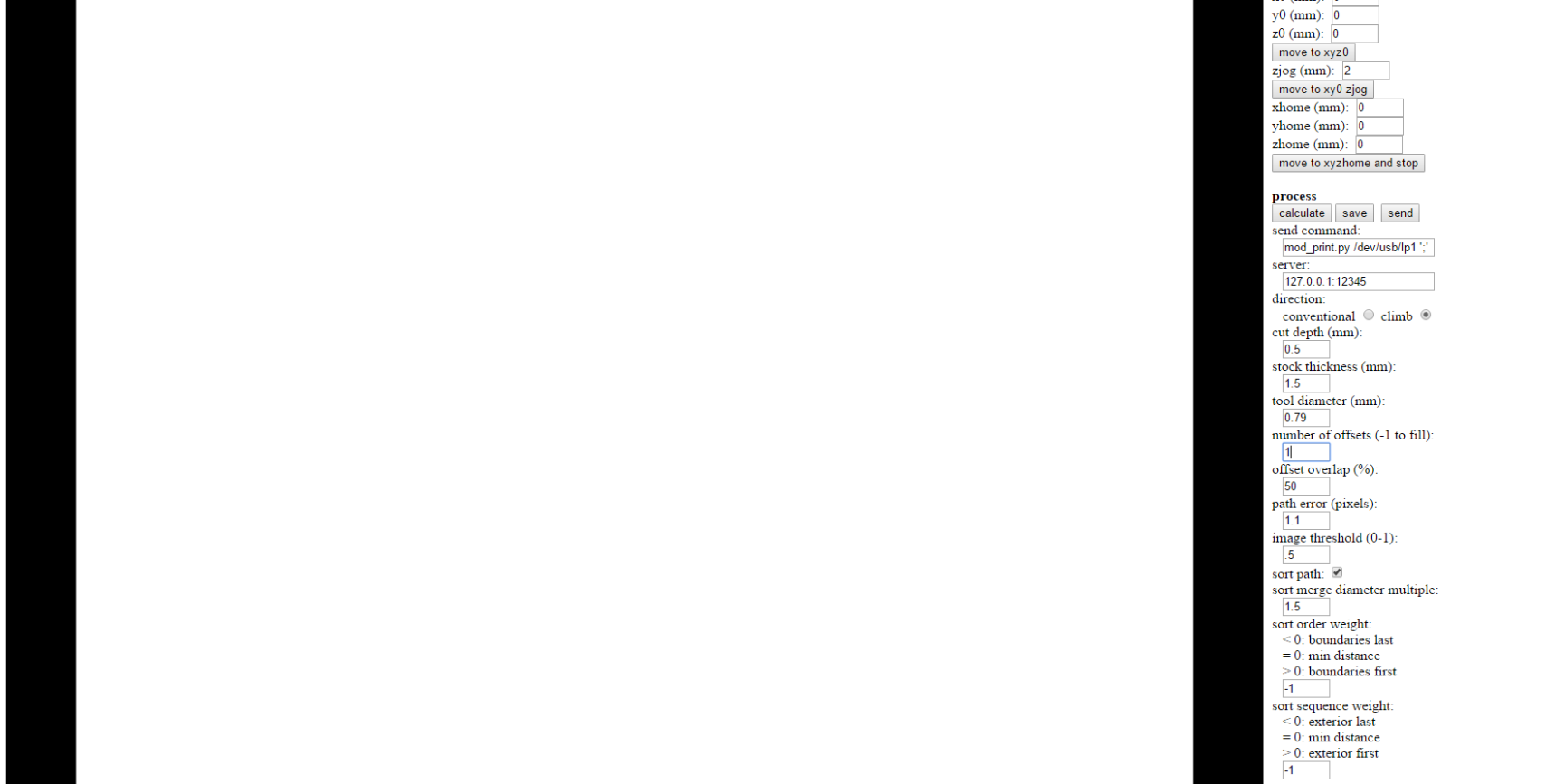
I used the border png again for the last operation to cut the board out completely. For this operation, I changed the drill bit from a 1/64 to a 1/32 and adjusted settings accordingly, with a cut depth of 0.5. This meant that the machine had to do 3 passes, but it is necessary to have a small step because these tiny drill bits are very delicate and can break if we try going too deep at once. Then I did the Z zero in situ this time, so I wouldn't cut too much into the base.
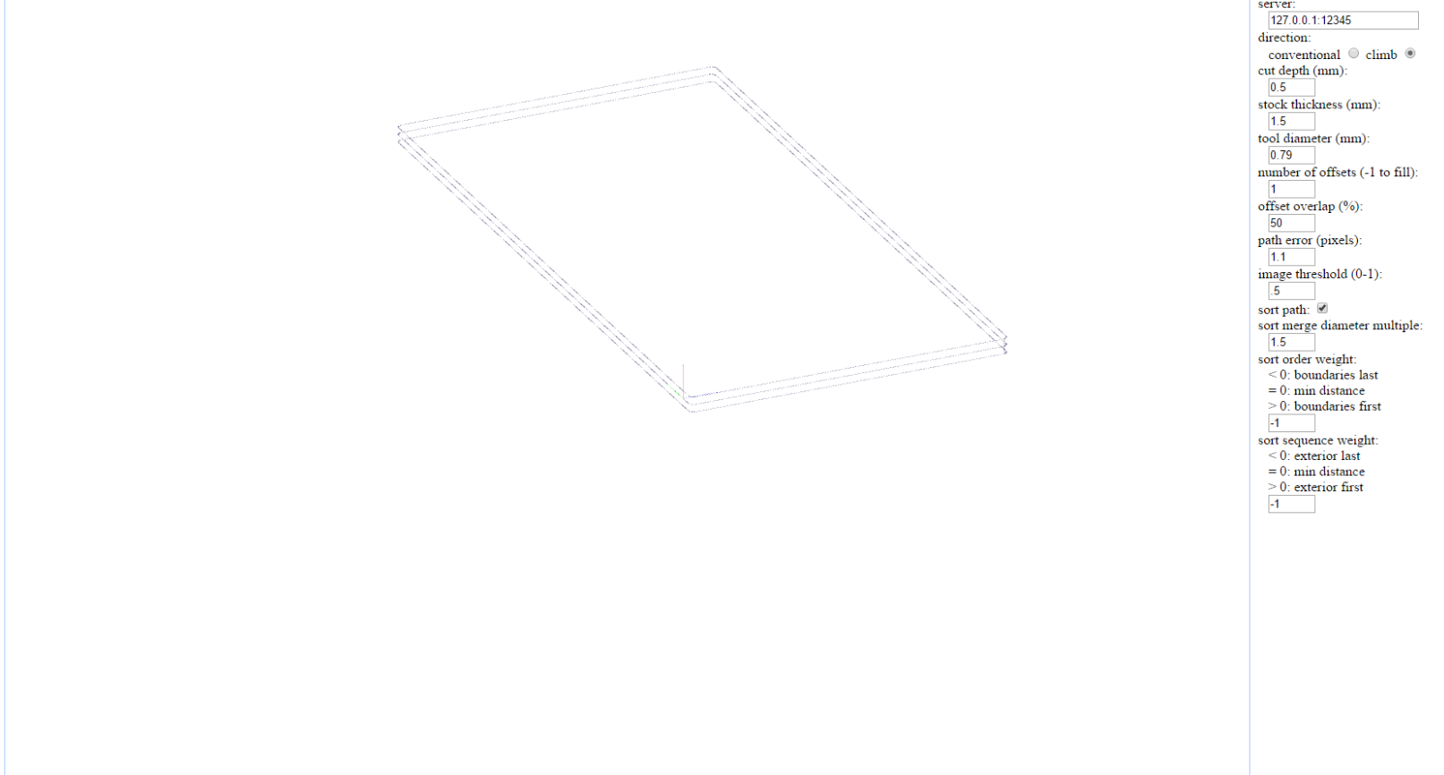
There is a small quirk here as well: Right before the machine finished milling, the head did an abrubt, fast jog to the zero position. We tried to figure out why it did that, but we couldn't really understand why that movement was there. As you can see from the last screenshot above, the g-code doesn't show such a movement. We think this movement is due to a mistake in the zjog parameter, but we couldn't confirm. This error didn't affect the board at all, but such movements are dangerous for the drill bit in general.
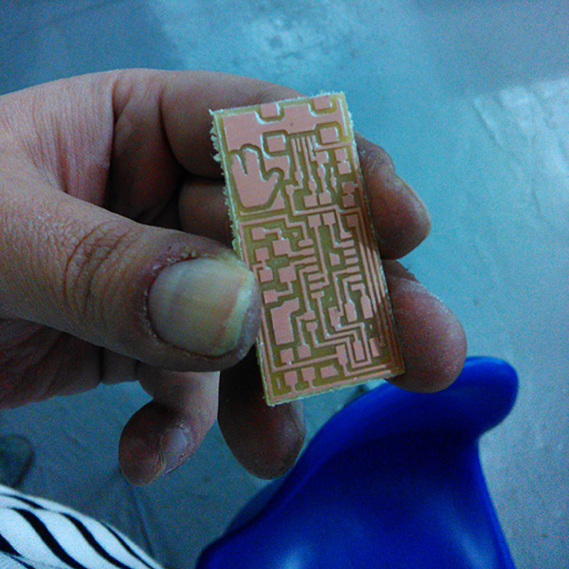
After I removed (i.e. pryed out with a screwdriver) the board, I went over it with steel wool and then cleaned it with soap and water.
Surface Soldering The Components
This was a painstakingly delicate process because I had never even held a soldering iron before. After a couple of tries with some unused boards and spare components though, I think I got the hang of it.
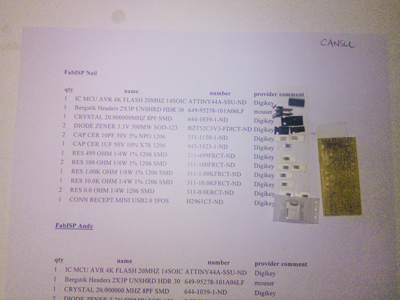
I gathered the components on the list, very carefully, from the boxes in the lab and then used double sided tape to secure them.
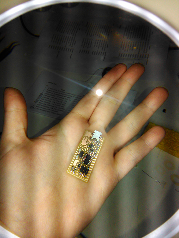
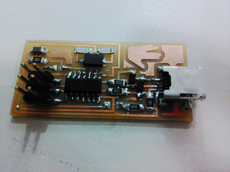
I don't have many photos of the process itself, as I was hunched over the tiny details the whole time. So here is the finished board, ready for inspection:
I found out the hard way that it's best to heat the pad with the soldering iron and melt the solder on the now-heated pad. This gave much cleaner results. But for some of the tight joints I used the method of melting solder on the tip of the iron and sort of smudging it on the intended joint. A couple of times I actually melted the solder on the leg of a component, which provided a surprisingly good result of really shiny and volcanoe-y joints. I will confess right here and now that I actually intentionally put solder everywhere and clean it up with the tip of the iron a couple of times because it was too tight a space for my inexperienced hands.
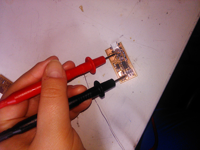
After the first round, I checked the board with a multimeter to see if there were any bad joints or shorts in the circuit. Unsurprisingly, there were. I went over them with the iron again.
Preparing The Board For Use
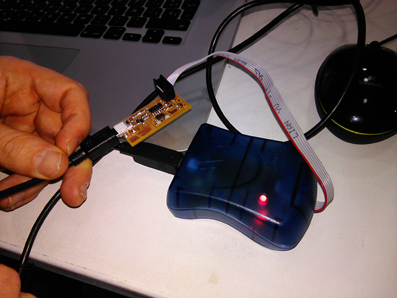
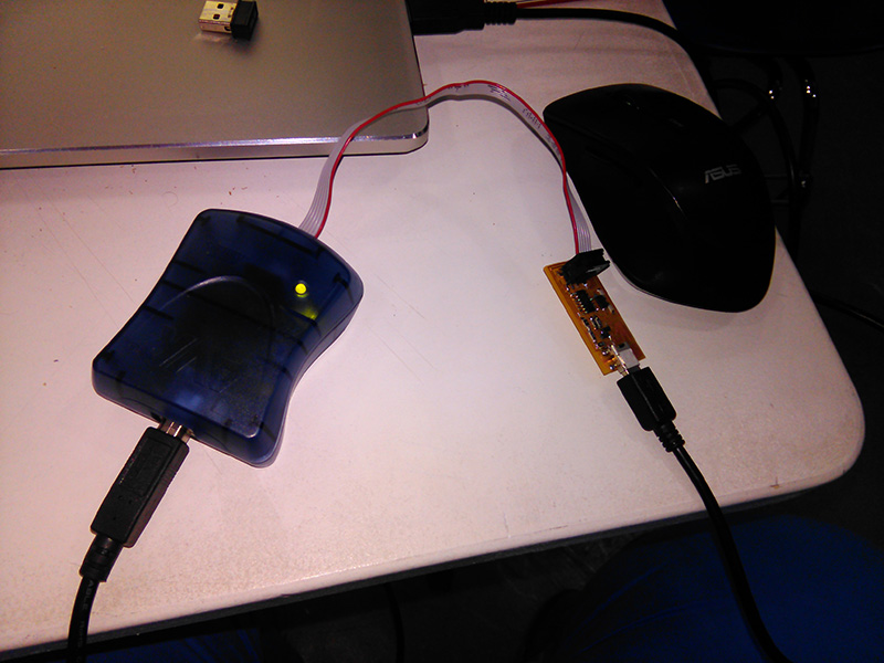
After I was certain the board was physically ready it was time to program it so it can be used as the Great Creator intended. I opened the tutorial here. So I tried to work on my own Windows 8 laptop, but failed miserably. I believe this problem is caused by the AVR drivers, but I can't be certain. But I know no Windows users were able to get the software to work on their computers either. So, I asked for help from a friend, and did the programming on his Mac. (Thanks, Arnau! ) He had already done the setup steps so I just ran the commands necessary to program the ISP. Here are the commands I used in order:
     cd Desktop/fabISP_mac.0.8.2_firmware
     make clean
     make hex
     make fuse
     make program
Here is the result:
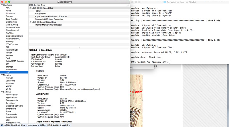
After the programming was done, I desoldered the two 0-ohm resistors.
Conclusions
This week was special for me because it was the first week that I actually had no idea about the subject. I had never worked with electronics before, save for a few "experiments" in elementary school.
The soldering took me 2 hours in total, with all my trials on spare boards and all my mistakes on the actual board. I think for someone as inexperienced as me, that counts as a success. I had to rework only a couple of joints, and one of them was in the tightest space of the board.
This opens up a whole world of possibilities for me as a designer because I now have dipped my toe in the waters of electronics and I like it.