| Final project: MoMoB MODULAR BODY SENSORS |
| | | | | | | | | | | | | | | | | | | | | | | | | | | | | | | | | | | | | | | | | | | | | | | | | | | | | | | | | | | | | | | | | | | | | | | | | | | | | | | | | | | | | | | | | | | | | | | | | | | | | | | | | | | | | | | | | | | | | | | | | | | | | | | | |
MoMoB MODULAR BODY SENSORS
>>>BACKGROUND:
My idea of final project is to continue working on part of a project I started on 2014 with the colombian composer Nicolás Villa and the chilean visual artist Andrés Costa. It began as a final project for our Master's Degree in Digital Arts @ Pompeu Fabra - Barcelona, but it became a constat motivation to keep on working on emboddiment and technology.
The project was called "[no dispositivo]", an artistic installation that involved dance theory, embodiment, coreography and our first experiment with robotics. The whole idea was to explore concepts around experiencing PERCEPTION OF HUMAN PRESENCE determined by MOVEMENT.
At that time (2014) , we developed a wearable system using an Arduino MEGA, 3 axis accelerometers and flex sensors. The programming was made with MAX MSP, using the open source project Maxiuno that allows Cycling '74's software to communicate eith the i/o of the Arduino bards.
We recorded on video and data from the body movement in a .txt file, that later on was used in the installation, activating robots, lights and video.
You can read the compete theoretical and techical documentation in our website by clicking here not a device project.
FAB ACADEMY PROJECT IDEA:
MoMoB MODULAR BODY SENSORS
As "n_n collective" (yes, this is our name) we are now working on a performance project called "CINESTESIA: Dispositivos para una algoritmia del cuerpo". As my final project I decided to develop tiny wearable modules that could communicate through them and with the computer in order to activate several actions happening in stage. The goal is to extend movement as a generator of dialogues between artificial entities and the human body.
I mainly focused on the development of the customized board that could read any input data from conductive fabric made sensors using the radio module that I worked during networking and communications assignment week.
PROJECT ACHIEVEMENTS:
Modular body - Final project summary.* from Citlali Limonada on Vimeo.

| | | | | | | | | | | | | | | | | | | | | | | | | | | | | | | | | | | | | | | | | | | | | | | | | | | | | | | | | | | | | | | | | | | | | | | | | | | | | | | | | | | | | | | | | | | | | | | | | | | | | | | | | | | | | | | | | | | | | | | | | | | | | | | | |
DOCUMENTATION:
A) [TURBULENTINO] + nRF24L01
I started using [TURBULENTINO] as the receiver board. But, suddenly the board stopped being recognized by any computer :( . It seems that ATMega32U4 is working because it's making the white led on the pin 13 blink.
I decided to use an Arduino Uno, while I was designing and working on the MOMO board which will be attached to the body.
| | | | | | | | | | | | | | | | | | | | | | | | | | | | | | | | | | | | | | | | | | | | | | | | | | | | | | | | | | | | | | | | | | | | | | | | | | | | | | | | | | | | | | | | | | | | | | | | | | | | | | | | | | | | | | | | | | | | | | | | | | | | | | | | |
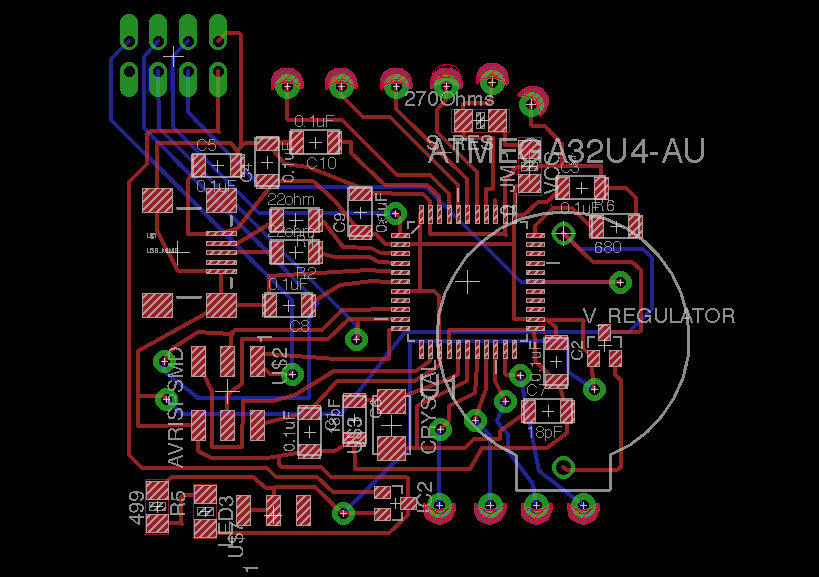
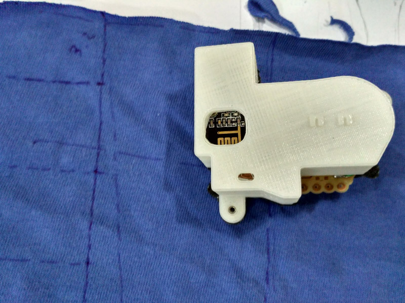
B) MOMO: MOdular MOtion Board (1st version)
For this design, I started working on what I've learned from [turbulentino] but I changed to luizino's - Fab Leo's version. This is because he had already deleted the reset button and the 2 leds. This was helpful to reduce the size of my board.
Components added:
Circuit for bend sensor was integrated, based on my Input Devices Assignment.
Radio Module circuit was integrated, based on my Networking and Communications Assignment.
Footprints added: Small Sew Tabs from Lilypad's Eagle library.
_b1) MOMO DESIGN
BOM
| Part | Value | Device | Package | Description |
|---|---|---|---|---|
| BAT1 | BATTERY20PTH | BATTCOM_20MM_PTH | Battery Holders | |
| C1 | 0.1uF | CAP-US1206FAB | C1206FAB | |
| C2 | 0.1uF | CAP-US1206FAB | C1206FAB | |
| C3 | 0.1uF | CAP-US1206FAB | C1206FAB | |
| C4 | 0.1uF | CAP-US1206FAB | C1206FAB | |
| C5 | 0.1uF | CAP-US1206FAB | C1206FAB | |
| C6 | 18pF | CAP-US1206FAB | C1206FAB | |
| C7 | 18pF | CAP-US1206FAB | C1206FAB | |
| C8 | 0.1uF | CAP-US1206FAB | C1206FAB | |
| C9 | 0.1uF | CAP-US1206FAB | C1206FAB | |
| C10 | 0.1uF | CAP-US1206FAB | C1206FAB | |
| IC2 | REGULATORSOT23 | SOT23 | ||
| LED3 | LED1206 | 1206 | ||
| NRF24L01+ | NRF24L01+ | NRF24L01+ | 2X04_THRU | nRF24L01+ 2.4GHz Wireless Transceiver module |
| R1 | 22ohm | RES-US1206FAB | R1206FAB | Resistor (US Symbol) |
| R2 | 22ohm | RES-US1206FAB | R1206FAB | Resistor (US Symbol) |
| R5 | 499 | RESISTOR1206 | 1206 | |
| R6 | 680 | RES-US1206FAB | R1206FAB | Resistor (US Symbol) |
| S_RES | 270Ohms | RES-US1206 | R1206 | Resistor (US Symbol) |
| U$1 | USB_MINIB | USB_MINIB | USB_MINIB | |
| U$2 | AVRISPSMD | AVRISPSMD | 2X03SMD | |
| U$3 | CRYSTAL | CRYSTAL | 2-SMD-5X3MM | |
| U$4 | SEWTAP11 | SEWTAP11 | PETAL-TINY | |
| U$5 | SEWTAP11 | SEWTAP11 | PETAL-TINY | |
| U$6 | SEWTAP11 | SEWTAP11 | PETAL-TINY | |
| U$7 | SPDTSWITCH | SPDTSWITCH | SPDTSWITCH | |
| U$8 | SEWTAP11 | SEWTAP11 | PETAL-TINY | |
| U$9 | SEWTAP11 | SEWTAP11 | PETAL-TINY | |
| U$10 | SEWTAP11 | SEWTAP11 | PETAL-TINY | |
| U$11 | SEWTAP11 | SEWTAP11 | PETAL-TINY | |
| U$12 | SEWTAP11 | SEWTAP11 | PETAL-TINY | |
| U$13 | SEWTAP11 | SEWTAP11 | PETAL-TINY | |
| U$14 | SEWTAP11 | SEWTAP11 | PETAL-TINY | |
| U$15 | SEWTAP11 | SEWTAP11 | PETAL-TINY | |
| U$16 | SEWTAP11 | SEWTAP11 | PETAL-TINY | |
| U1 | ATMEGA32U4-AU | ATMEGA32U4-AU | QFP80P1200X1200X120-44N | 8-bit Microcontroller with ISP Flash and USB Controller |
| VCC | 0_JMP | RES-US1206 | R1206 | Resistor (US Symbol) |
| V_REGULATOR | REGULATORSOT23 | SOT23 |
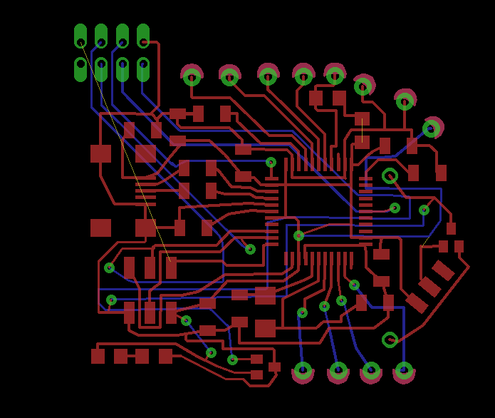
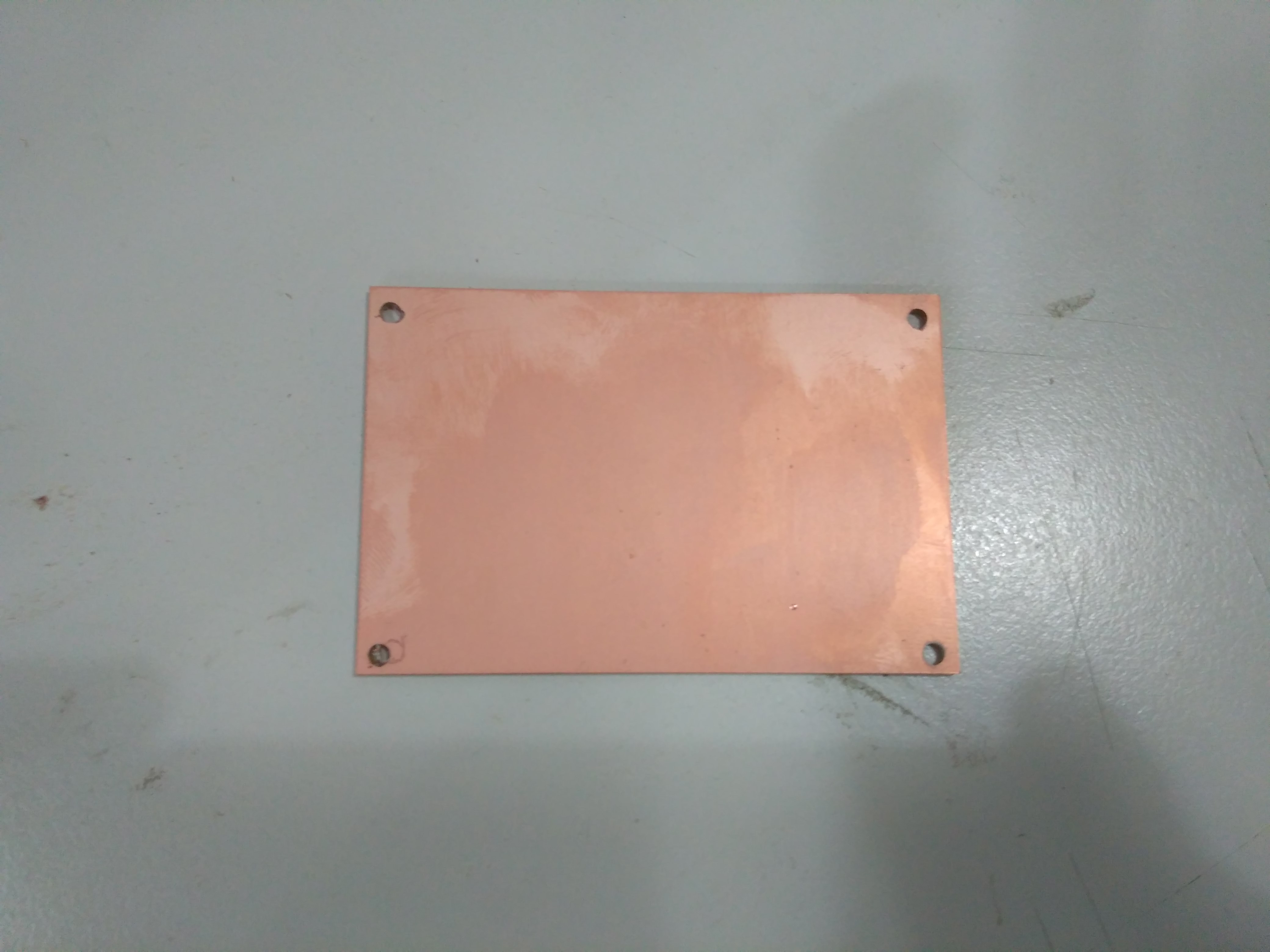
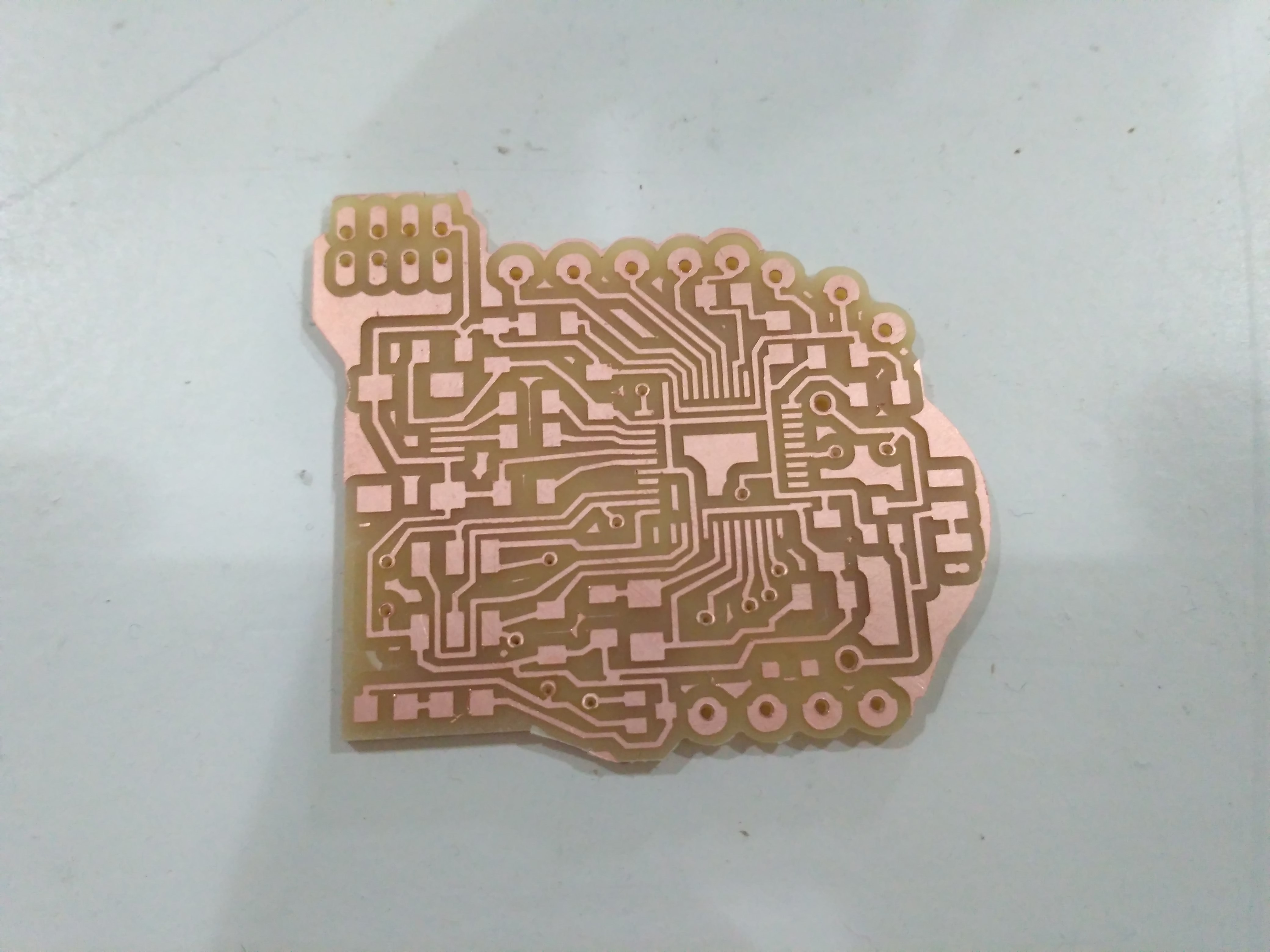
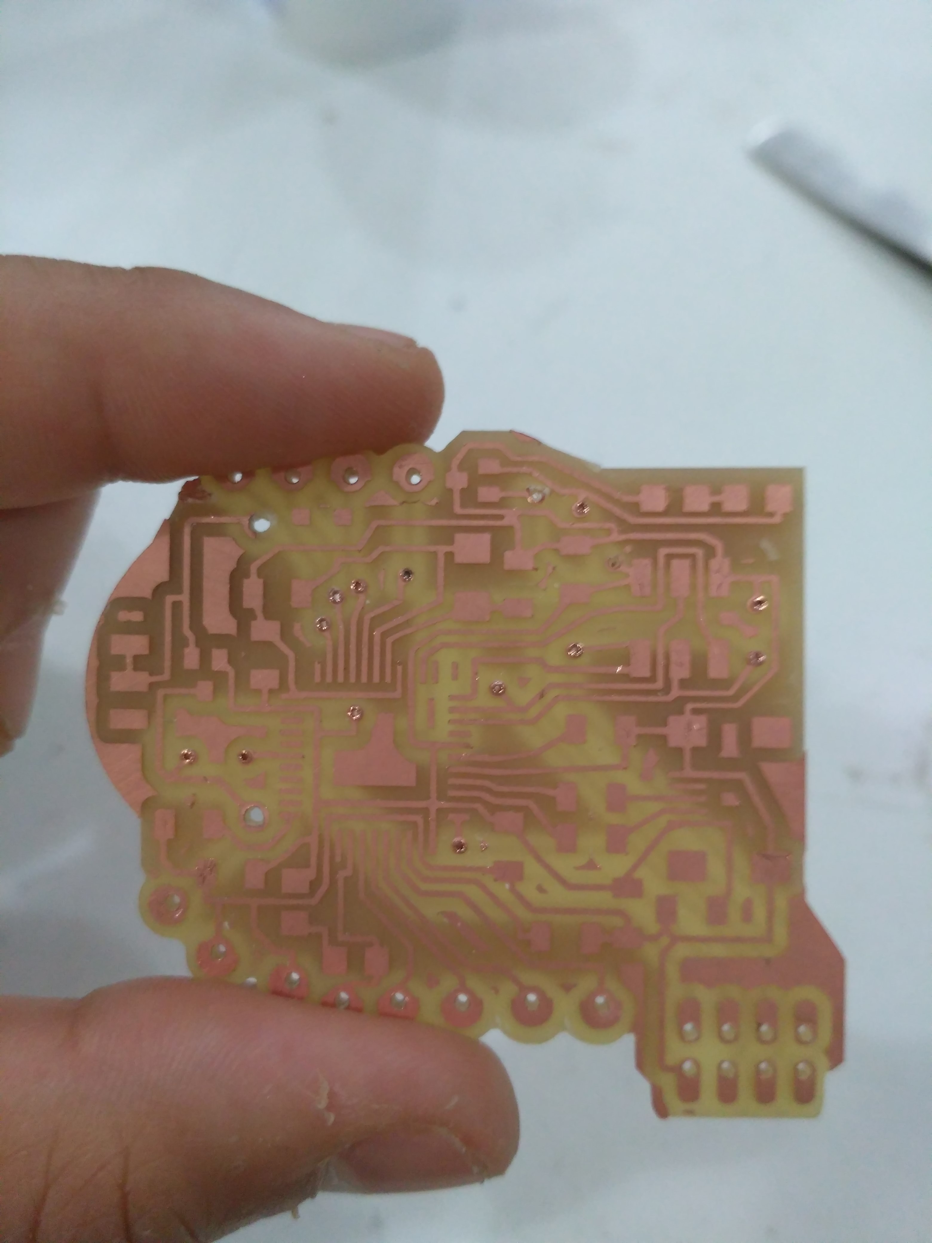
This time I made a double sided board to avoid increasing it's size. It was hard and complicated to learn, but I really enjoyed this process.
IMPORTANT!
If you want to create a double sided board you will need to add "VIAS" with the correct diameter hole size in your eagle file. Because of not knowing exactly how do this, I repeated my EAGLE design for about 5 times. It was horrible. :( But now that I know, let me tell you that YOU'LL NEED A 0.6 Mm. Diameter VIA hole.
- Select your component and make a path in the "top" layer.
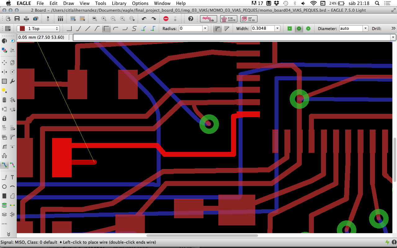
- When you think it's time to add a VIA change your layer to "bottom" and the via will automatically appear.
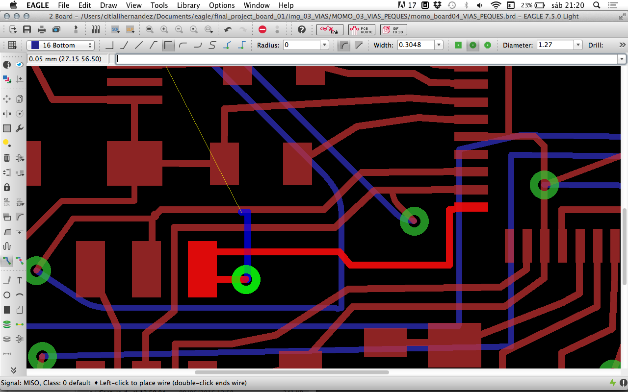
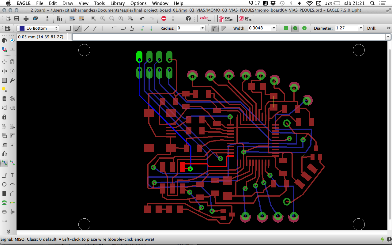
- Don't forget to constantly check DRC - Clearance. :D
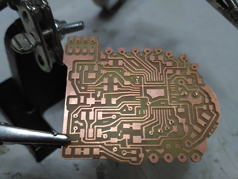
Complete board
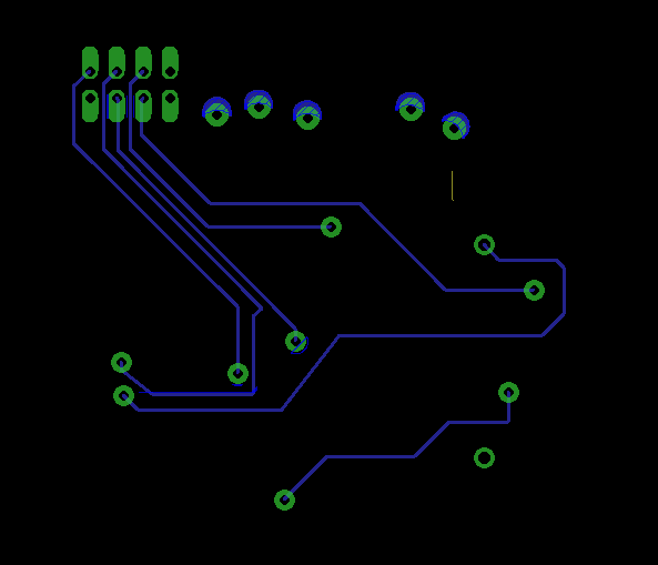
Layer from below
_b2)PREPARING FILES TO MILL
- In your Eagle file go to: file, Run ULP.
- Add monofab-eagle.DXF , file created by Ferdi. This is actually the drawing of the sacrificial bed made in MDF that we have for the Roland, SRM-20. It includes 4 holes for a board that is less than 50x50 Mm. Download me!
- Drag the 4 holes as a group around your board into the "Dimension" layer.
- Export your top & down images as you usually do but including in all of them the Dimension Layer. Monochrome, 1000 DPI's. You'll need high resolution because of the size of the vias. ( You can also try with 2000 DPI's, but later on we found out that fabmodules sometimes does not like to load this resolution images ).
_b2.1 PREPARING THE IMAGES IN PHOTOSHOP (or GIMP)
- Import your files in the same .psd file.
- Every image should be in a different layer.
SUPER IMPORTANT! The 4 holes in the corners will help you to make all of the layers match and be in the same position. If you don't do this, you will not succeed. :D
- Flip your "bottom traces" and the "outline path" horizontally or vertically, and make sure the 4 holes in the corners match with the ones in the other layes. ( Transform --> flip --> horizontal)
- Crop your file untill it the crop area reaches the 4 circles' edge.
- Go to "Image"--> "Canvas size" and add 1 mm. offset.
- Export your .png files
My files:

PNGS ready for fabmodules
_b2.2 FABMODULES
- Make your .RML files as you normally do, but for the small vias holes there's a special process to follow.
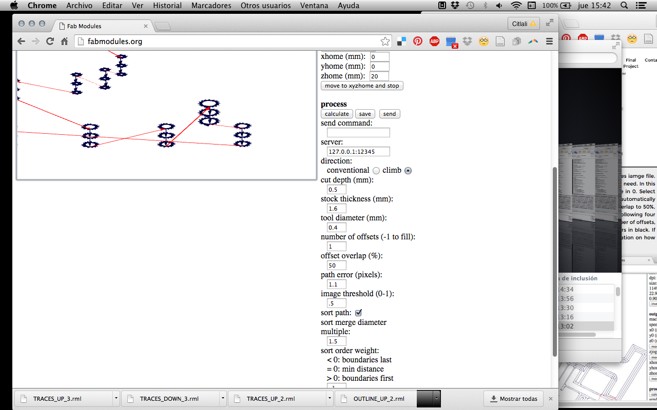
Preparing vias .rml
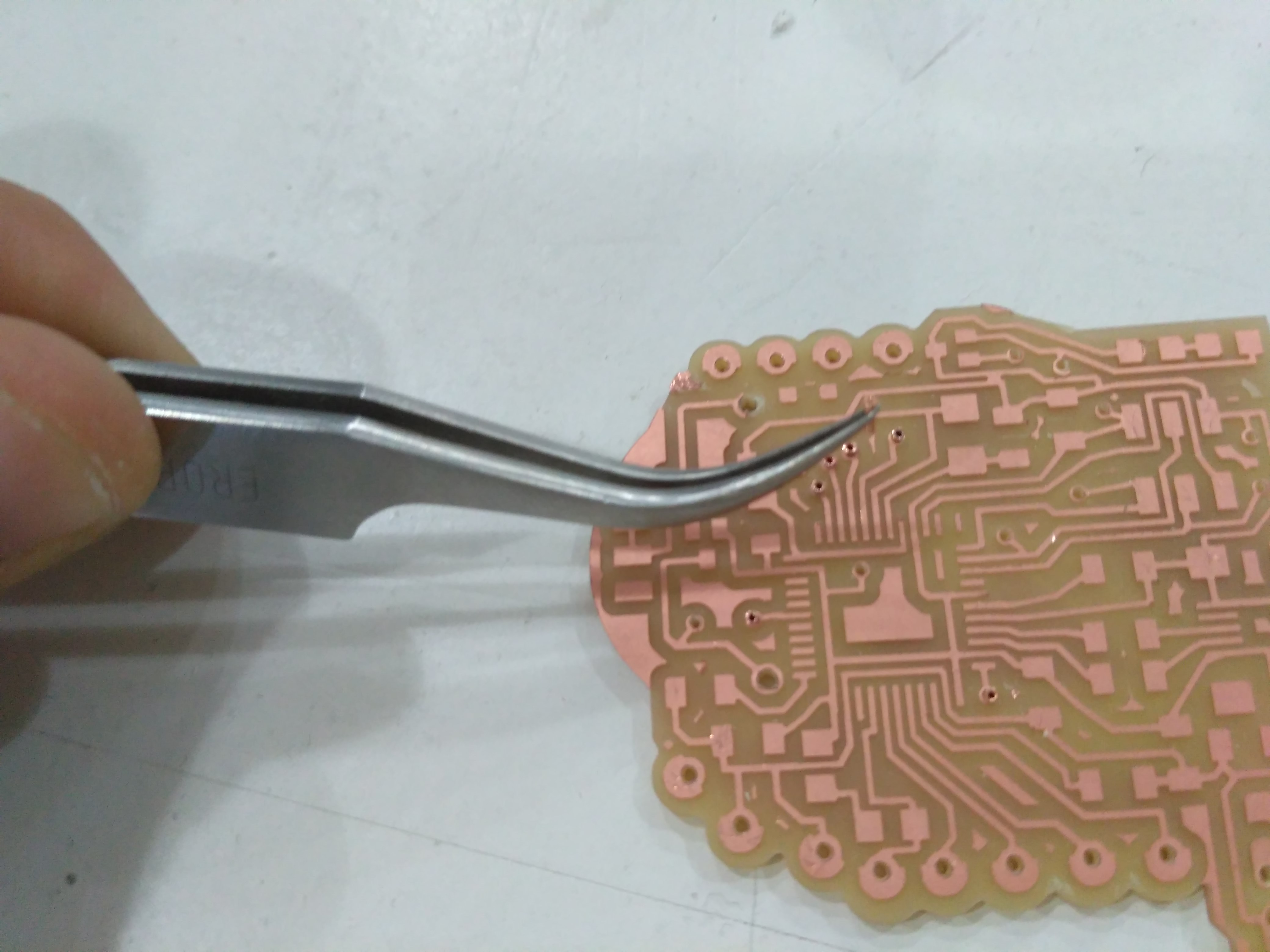
_b3) MOMO BOARD ASSEMBLY & SOLDERING
__b3_1: MILLING
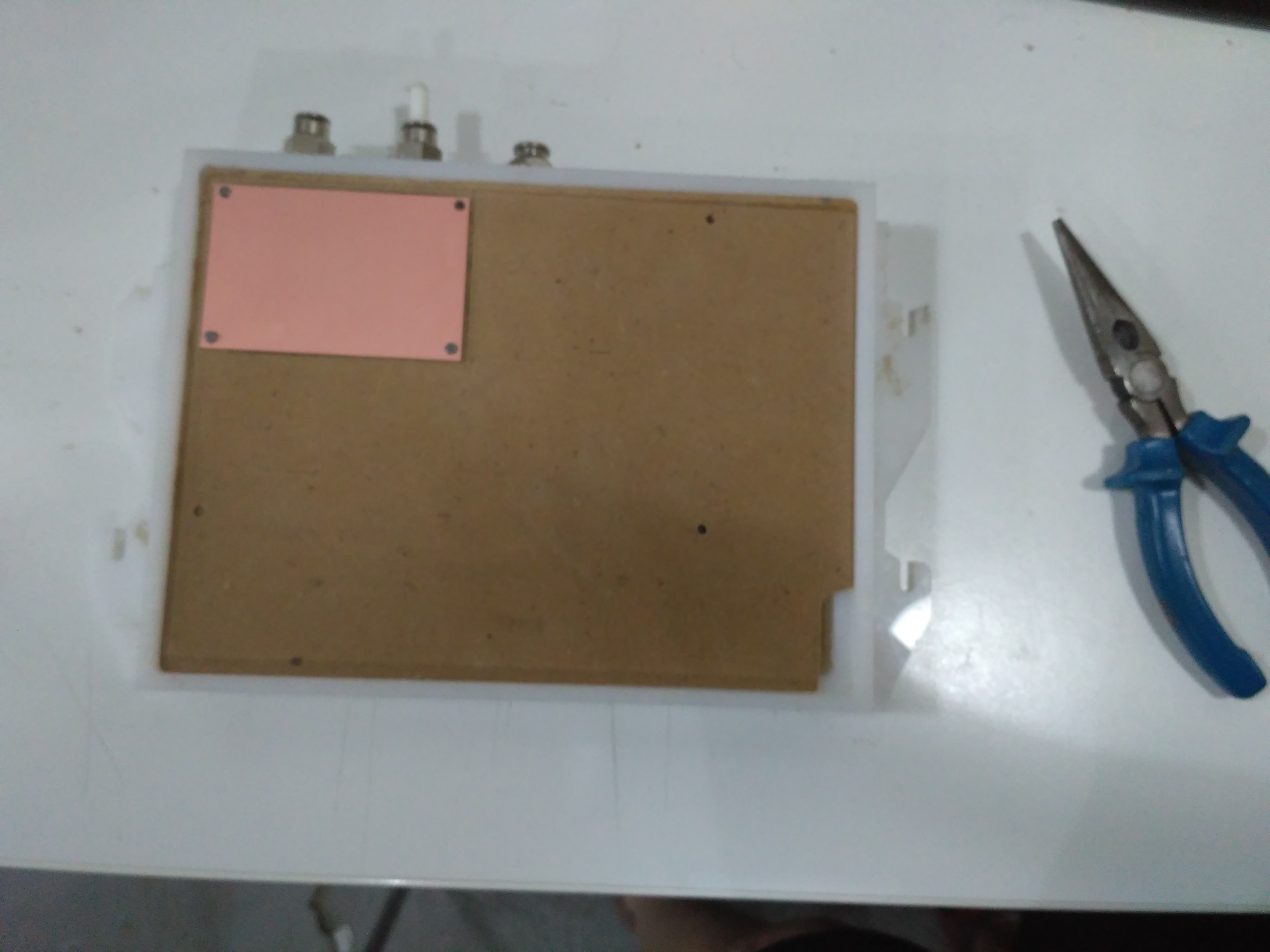
- I used the small double sided PBCS, this means that your board sould be less than 50x50 Mm.
- First of all, cut the 4 big holes from the "monofab" file from Ferdi, using the normal 1/32 tool from FabModules. Then use 4 small metal bars that Ferdi gave me and hold your board to the sacrificial board.
Cutting fixing holes
Placing copper board over sacrificial layer
- Mill your upper traces, and then the vias holes using the 1/64 tools with the specs that I've already mentioned.

Traces
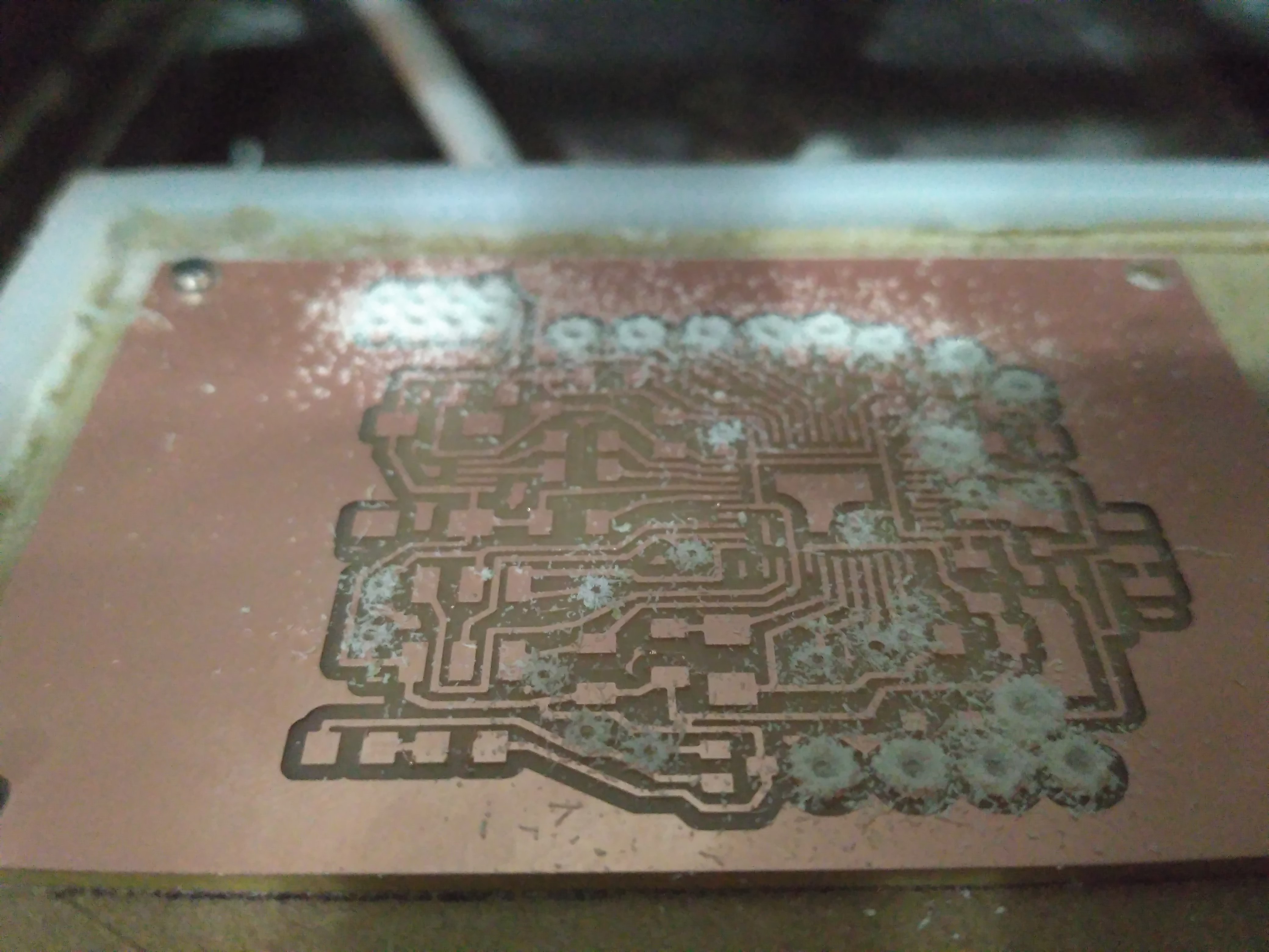
Small holes + Vias holes
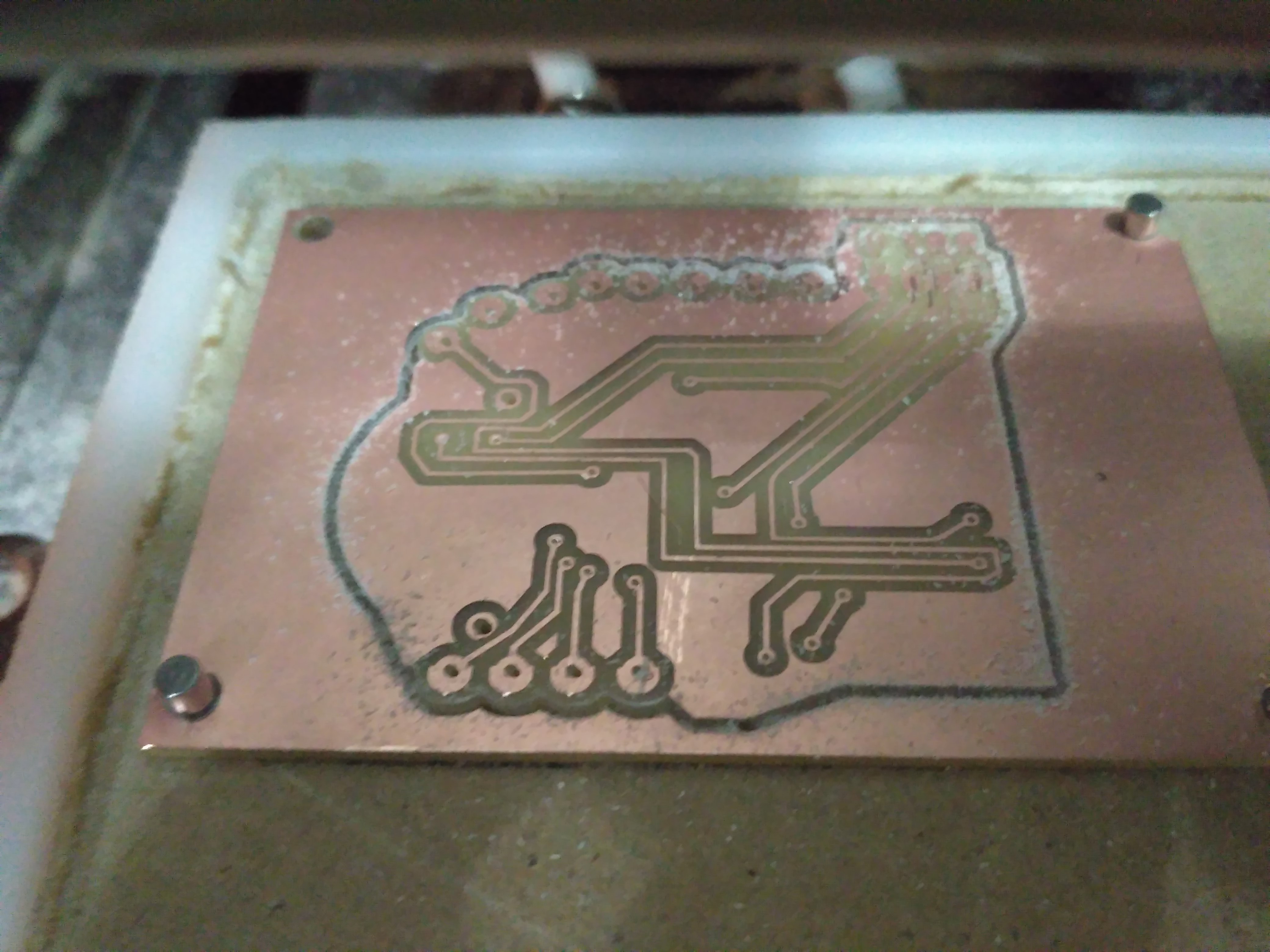
Small holes + Vias holes
By using this technique you'll find out that the 1/64 bit won't go all the way though the board, so you'll need to complete the holes using the Dremel Tool.
Final Board :D
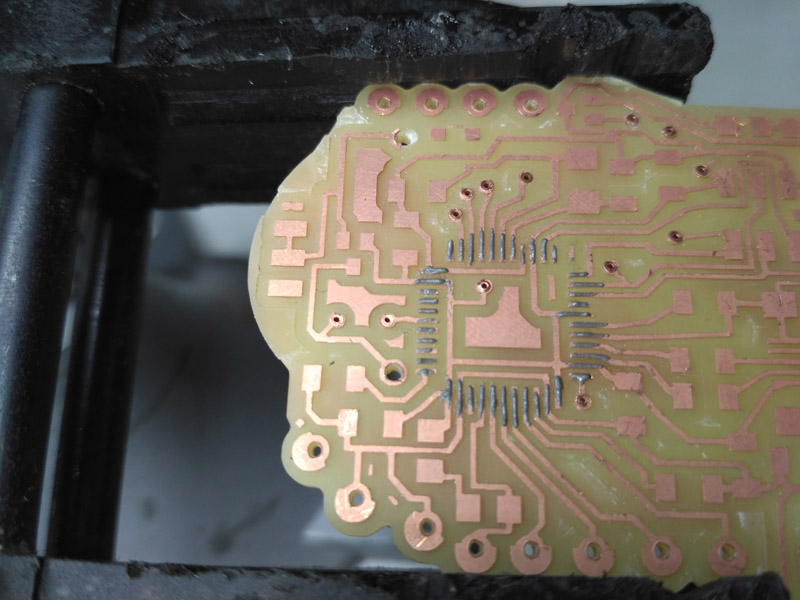
__b3_2: ADDING VIAS
-First you have to put manually all of the copper rivets. They are super small.
Placing copper rivets
Then use the rivet machine.
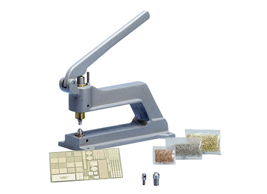
In the lab we had the "Bungard Favorit" riveting machine. At the beginning it seems to be very hard, but once hyou understand the process, you'll put every rivet very quickly. You have to be very careful though, because the metalic tips ar super tiny and because of their small diameter they can get bent very easily.
Riveting
Final Board :D
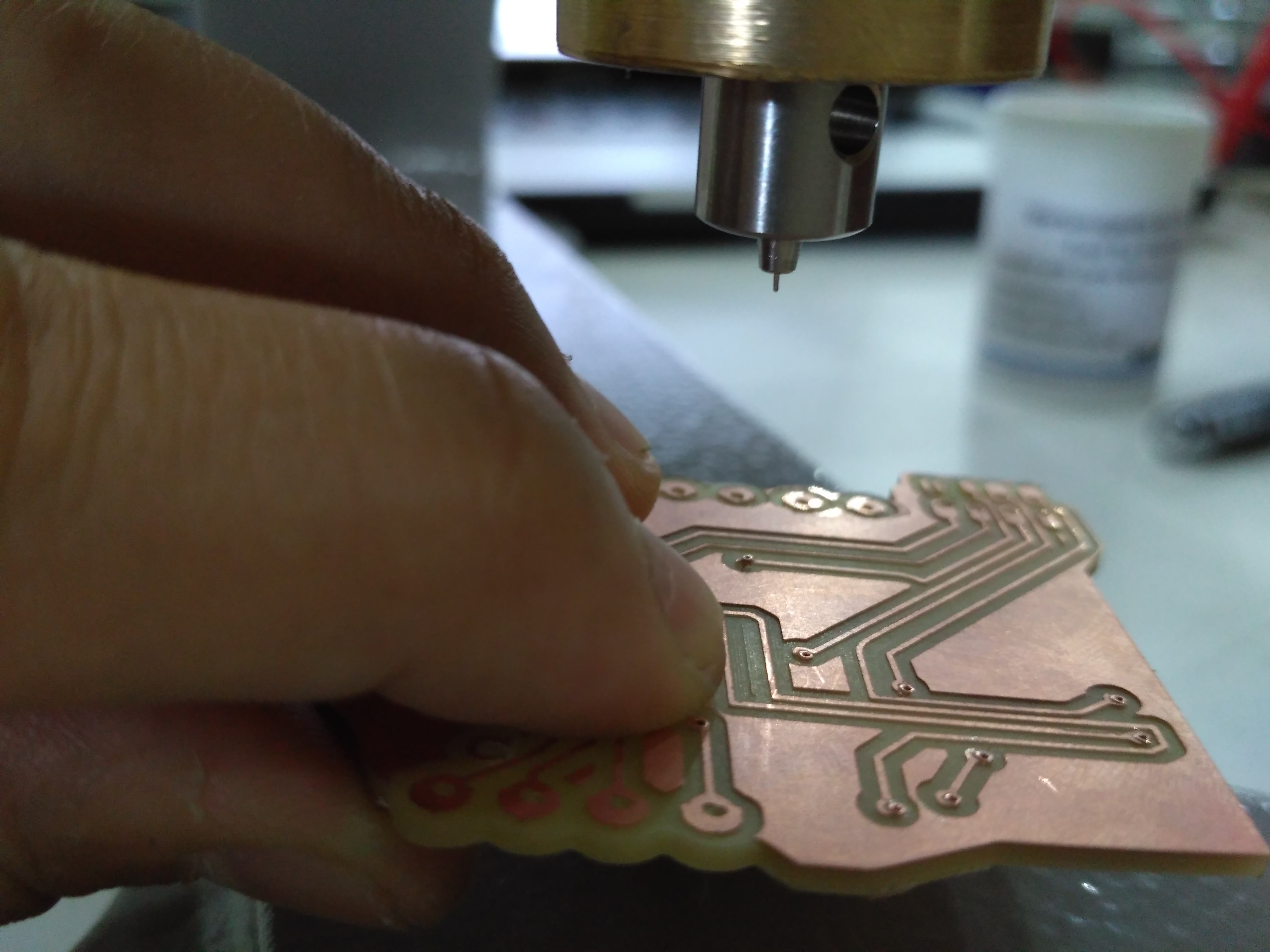
__b3_3: SOLDERING
- I began by I using soldering cold paste for the more tiny traces: ATMEGA32U4 and the mini USB connector.
Adding cold paste
Soldering paste already heated and melted
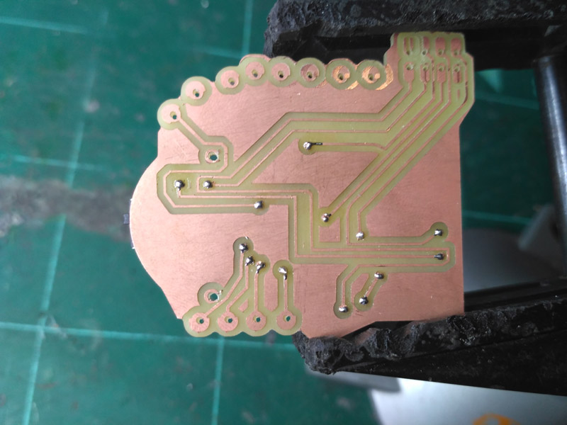
Bottom vias with solder.
As you can see in this last picture, when I milled the bottom part, the traces were misplaced. Ferdi and I couldn't understand why this was happening so we moved Y axis using the VPanel software.
One little problem that I faced is that the battery holder was bigger than I expected so I bent the metal legs and forced it into my MOMO board. This wasn't so nice because the PCB broke a little bit.
_b4) CHECKING CONNECTIONS
CAREFUL! I HAD A LOT OF PROBLEMS HERE!
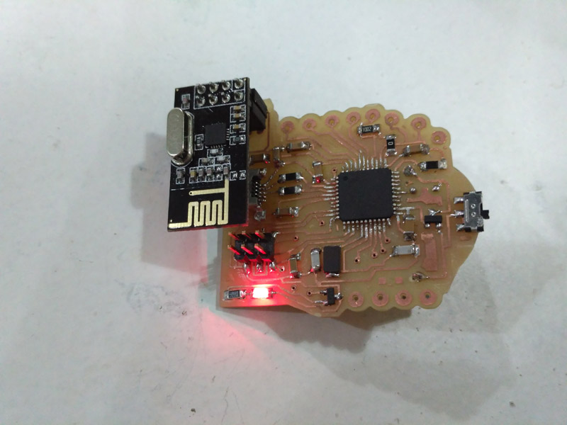
When the board was completely assembled, the littlered led turned on.
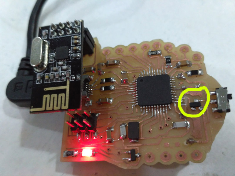
But I found out that the voltage regulator I added in order to change voltage from the two 3V. batteries (6v) to 5 V. didn't "liked" to be connected the way I did. When using the batteries, the MOMO board worked well but when I plugged it into my computer, this little regulator increased it's temperature a lot!
After a while I understood that I made a terrible mistake by connecting switch in the wrong spot.
I should have added it between the "5v out" of the voltage regulator and a VCC pin from the ATMega32u4.
TEMPORARY SOLUTION: Suggested by my tutor Ferdi, was manualy removing the copper connection between the voltage regulator to the VCC from the ATMega3232U4.
So the solution was to program the board like this, and when I finished making the programming and improving the code for radio communication and the sensor, I would add a wire between the 5v OUT from the voltage regulator and the ATMega32U4 VCC pin.
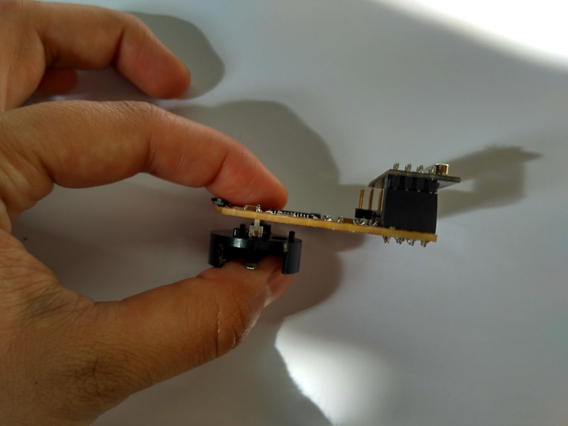
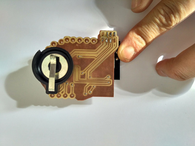
I have to say that when adding the batteries, I realized it was heavy and would create problems when sewing the board into fabrics.
Because of this situation I decided to put unsolder the battery holder and placed it in the top.
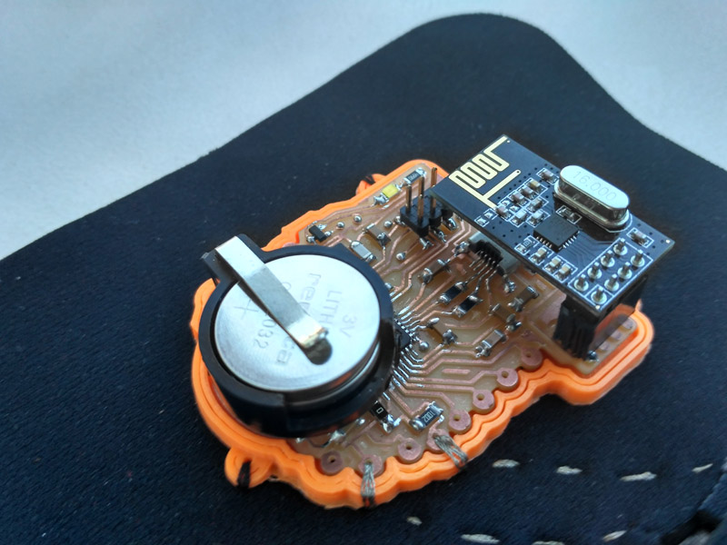
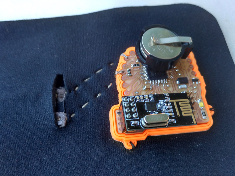
_b4: MoMoB Version 2
Milled and with rivets already placed.
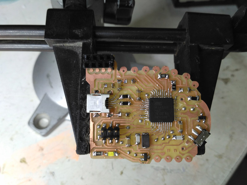
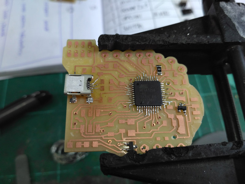
View of all components already soldered.
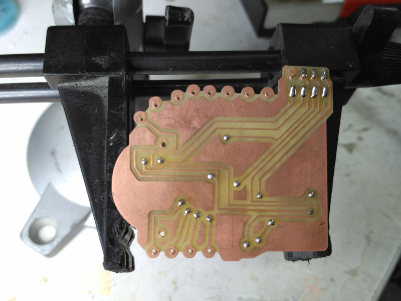
Bottom side with solder. I made this to make sure everything was connecting well.
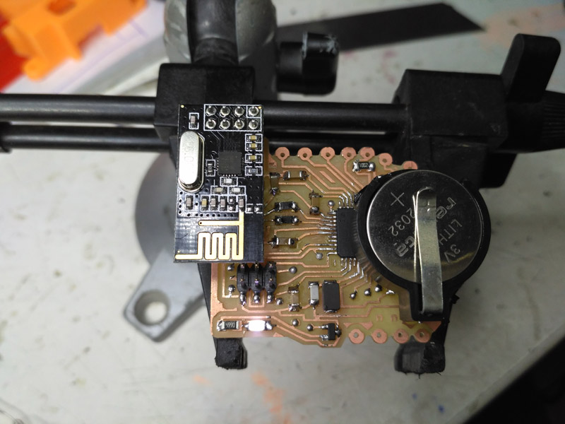
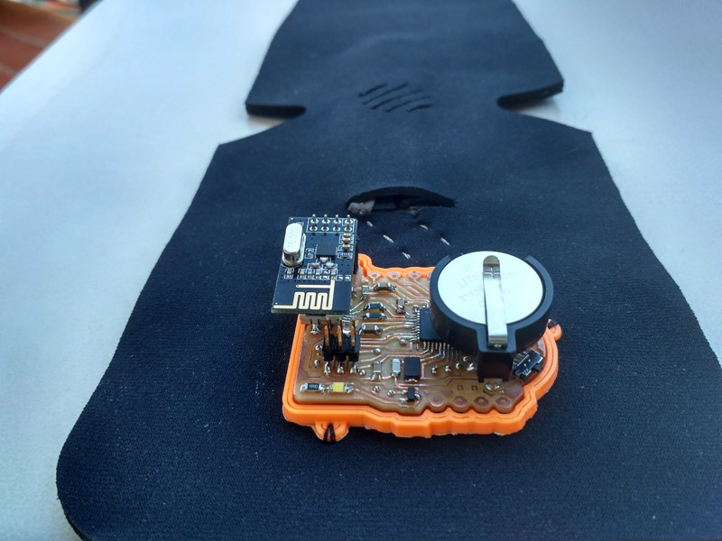
MoMoB with batteries in the top part. LED on, so it seems to be working!
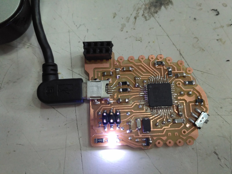
PCB working with USB cable. ( Don't forget to change switch position ).
_b5: Programming ATMega32U.
| | | | | | | | | | | | | | | | | | | | | | | | | | | | | | | | | | | | | | | | | | | | | | | | | | | | | | | | | | | | | | | | | | | | | | | | | | | | | | | | | | | | | | | | | | | | | | | | | | | | | | | | | | | | | | | | | | | | | | | | | | | | | | | | |
c) RADIO COMMUNICATION: Transmit & Receive
I used the code that I wrote for the network & communication assignment.
At the beginning I got scared because nothing seemed to be working. Radios were not communicating.
Finally I wired everything up again using MOMO board as a transmitter and Arduino UNO as a receiver, and the communication worked. To make sure this was for real I tested the receiver in another computer, and the values were received. :)
For this tests I used the bend sensor that I did for the Input Devices Assignment.
At some point I thought that the resistor that I added to the board in order to use the bend sensor, was not working. So I decided to make a little simple board with the 10K resistor on it. I made tests and everything worked. Later on I figured out that MoMoB 10K resistor was working fine too. :)
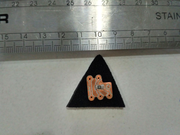
10K resistor sewing board
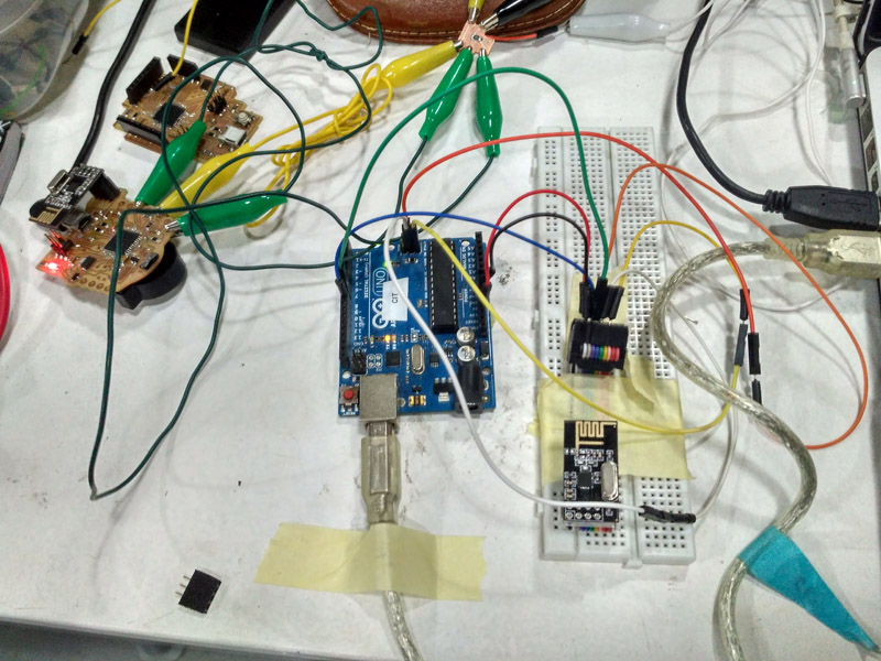
MoMoB & Arduino Uno
Arduino Code:
And a video of one of the tests I made using my MoMoB WORKING!!
Modular Body - Momo Board test no.1 from Citlali Limonada on Vimeo.
| | | | | | | | | | | | | | | | | | | | | | | | | | | | | | | | | | | | | | | | | | | | | | | | | | | | | | | | | | | | | | | | | | | | | | | | | | | | | | | | | | | | | | | | | | | | | | | | | | | | | | | | | | | | | | | | | | | | | | | | | | | | | | | | |
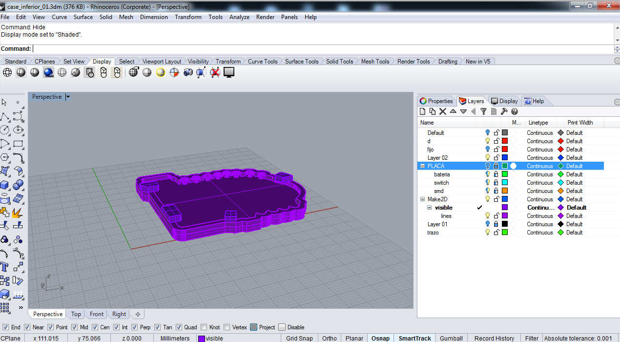
d) CASE DESIGN
_d.1) 1st Version
I first designed a complete case that would cover everything except the antena for the nrf24L01+.
I modeld using Rhino and printed with an Ultimaker 2
I also integrated in the design 4 of 3 Mm. headless blind allen screws.
Case V1 and MoMob V1
Notes about this case:
Not completely needed, it's too big and hard. The difficult part is to deal with the height of the nRf24L01+ and the 2 battery holder.
If you want to use it, download Rhino file: HERE
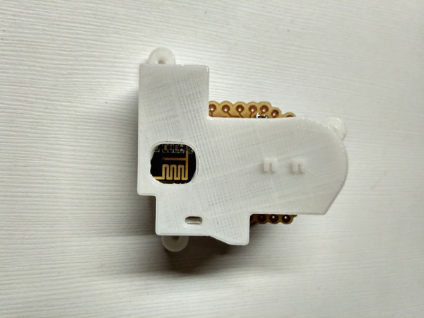
_d.2) 2nd Version
3D Modeling in Rhino
I decided to avoid covering the complete board and just to create a holding surface below it. When modeling it, I realized that PCB design should change from cell coin battery to a lipo one. But, at the end I liked the result.
The idea was to print using filaflex but all of the machines in FabLab were completely busy, as IAAC and us Fab Academy students were about to present final projects.
This is why I ended up using one of the Formbytes machines using orange PLA.
| | | | | | | | | | | | | | | | | | | | | | | | | | | | | | | | | | | | | | | | | | | | | | | | | | | | | | | | | | | | | | | | | | | | | | | | | | | | | | | | | | | | | | | | | | | | | | | | | | | | | | | | | | | | | | | | | | | | | | | | | | | | | | | | |
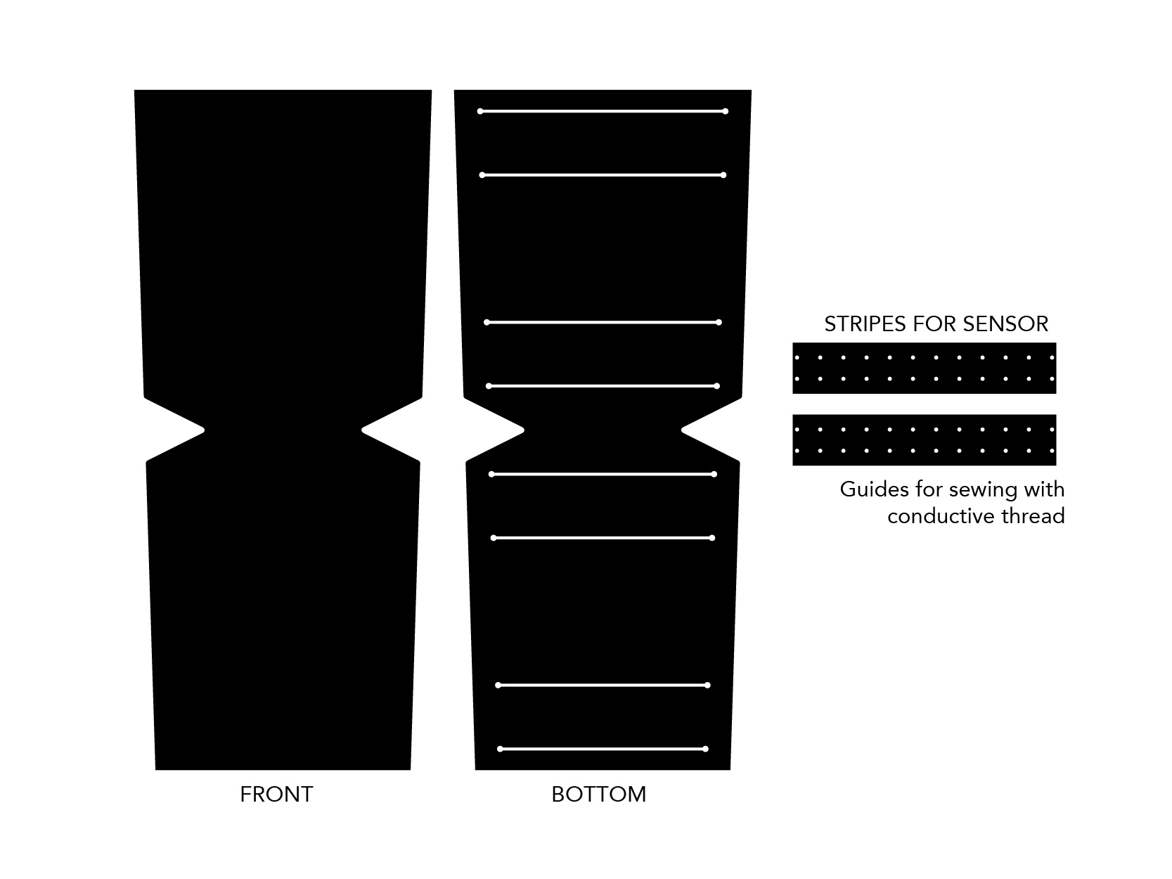
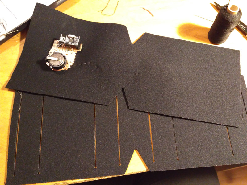
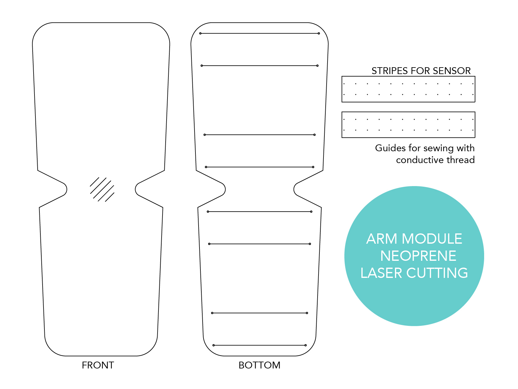
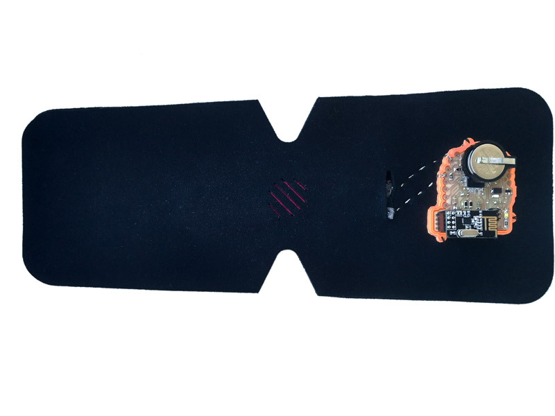
d) ARM MODULE
_d.1) BEND SENSOR
>>Materials:
You can look at the complete documentation on how I made this senso ny going into my made Input Devices Assignment. For my final project I replaced lycra for Neoprene and pink fabrics just to give it a little bit of colour.
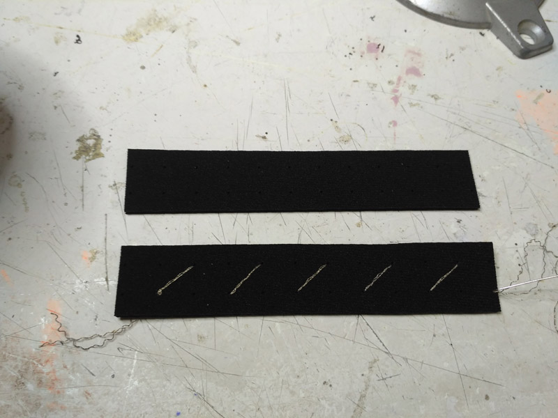
Making sensor
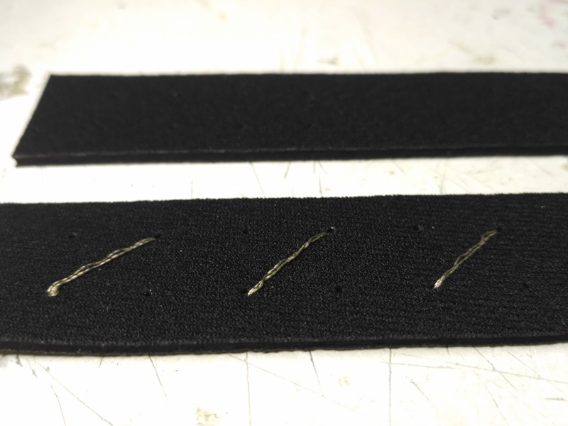
Making sensor
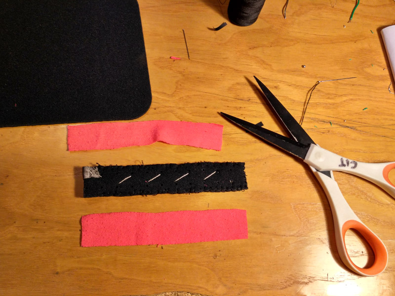
Making sensor
_d.2) ARM MODULE
>>> DESIGN: Product design guidelines
_>Ergonomics:
Keywords: Suitable for everybody including kids, soft, easy to adjust, intuitive to use.
_>Aesthetics
Keywords: Clean, Minimal, Organic
_>Functionallity:
Keywords:
_>Production:
Keywords: Laser cutting, Sewing, Conductive Fabrics, Piezoresistive materials
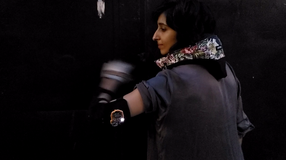
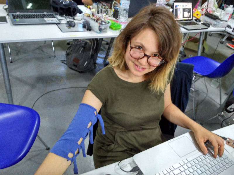
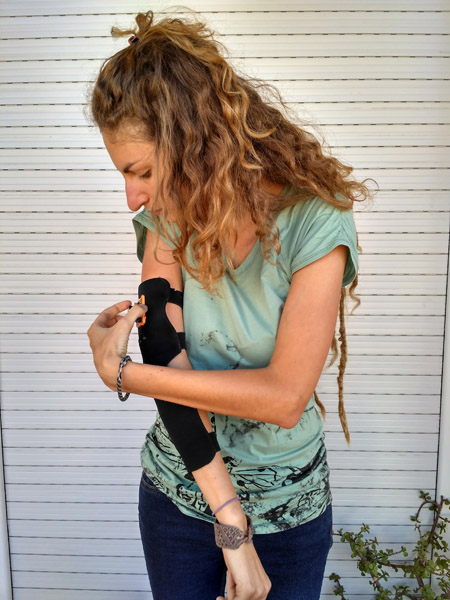
I started by making a prototype cutting an old t-shirt. My idea was to make it fittable for any arm size, including kids or adult people. But I realized it was more complicated than I expected, so at the end I decided to make it for the moment for me.
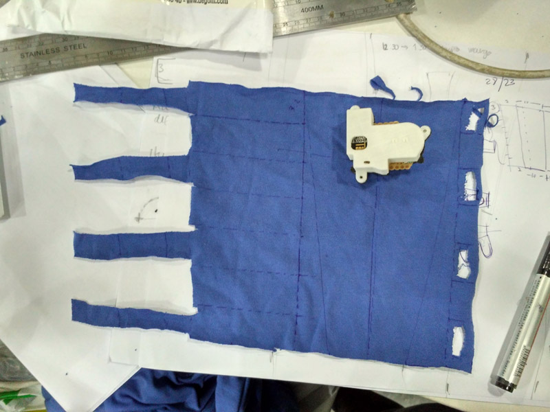
Visualizing arm module
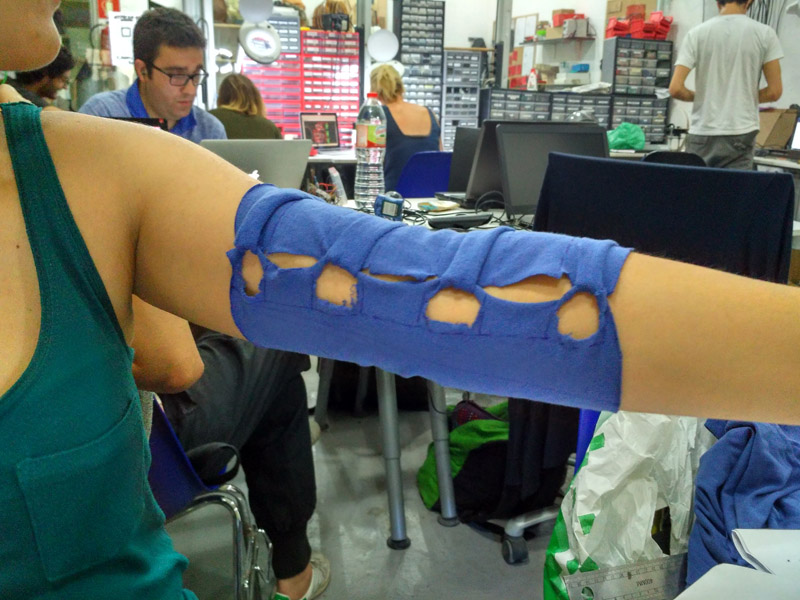
Wearing module test on myself
Understanding size and problems of Version 1 of MoMoB
The initial idea was to create a one time cut design including stripes that could wrap any size of arm. This is why I asked my classmates to wear the prototype.
Xavi
Caro
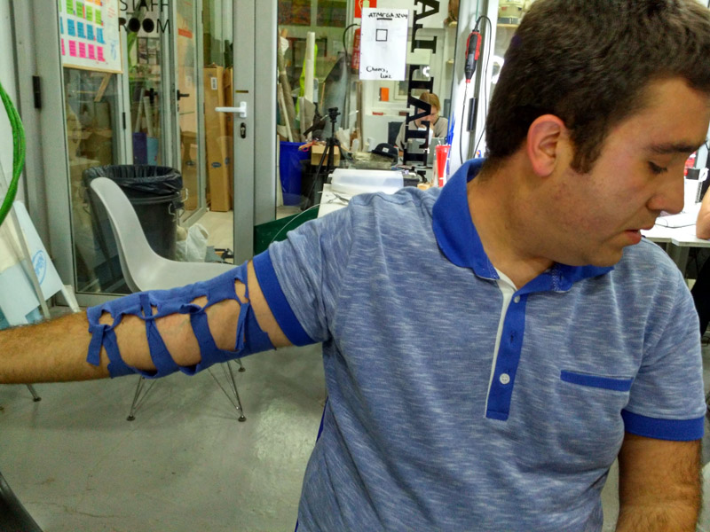
Then I experimented with some other ideas, and understood how 2 Mm Neoprene behaved in the elbow.
1st Neoprene Laser Cutting Design, Including Stripes for bend sensor.
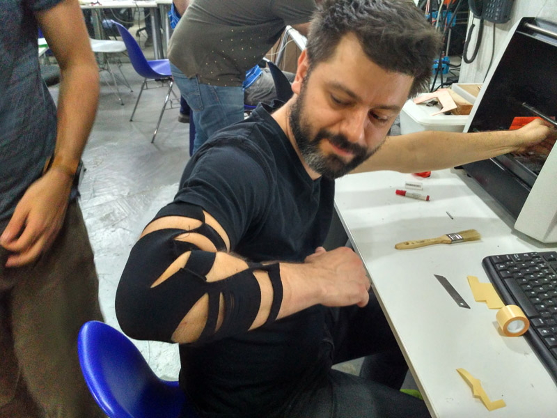
Elia wearing module test
Sewing tests
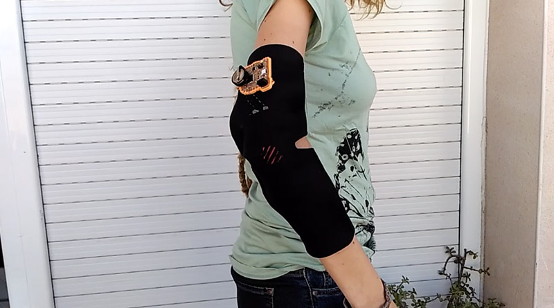
I didn't like the shape and the size, so I worked on another one which became the final module.
Arm Module Final Design
| | | | | | | | | | | | | | | | | | | | | | | | | | | | | | | | | | | | | | | | | | | | | | | | | | | | | | | | | | | | | | | | | | | | | | | | | | | | | | | | | | | | | | | | | | | | | | | | | | | | | | | | | | | | | | | | | | | | | | | | | | | | | | | | |
MoMoB: MODULAR BODY SENSORS
Arm Module Final Design
Arm Module Final Design
Arm Module Final Design
Arm Module Final Design
Arm Module Final Design
Arm Module Final Design
| | | | | | | | | | | | | | | | | | | | | | | | | | | | | | | | | | | | | | | | | | | | | | | | | | | | | | | | | | | | | | | | | | | | | | | | | | | | | | | | | | | | | | | | | | | | | | | | | | | | | | | | | | | | | | | | | | | | | | | | | | | | | | | | |
FILES
Neoprene: DXF
Code: Available to download it from my Gist Website.
| | | | | | | | | | | | | | | | | | | | | | | | | | | | | | | | | | | | | | | | | | | | | | | | | | | | | | | | | | | | | | | | | | | | | | | | | | | | | | | | | | | | | | | | | | | | | | | | | | | | | | | | | | | | | | | | | | | | | | | | | | | | | | | | |
Thanks to Neil Gershenfeld Ferdinand Meier, Santiago Fuentimilla, Luciana Asinari, Fab Lab Barcelona and all of my classmates. It was the most exhausting working period of my life, but it was completely worth it!
| | | | | | | | | | | | | | | | | | | | | | | | | | | | | | | | | | | | | | | | | | | | | | | | | | | | | | | | | | | | | | | | | | | | | | | | | | | | | | | | | | | | | | | | | | | | | | | | | | | | | | | | | | | | | | | | | | | | | | | | | | | | | | | | |
| | | | | | | | | | | | | | | | | | | | | | | | | | | | | | | | | | | | | | | | | | | | | | | | | | | | | | | | | | | | | | | | | | | | | | | | | | | | | | | | | | | | | | | | | | | | | | | | | | | | | | | | | | | | | | | | | | | | | | | | | | | | | | | | |

MoMoB by Citlali Hernandez Sanchez is licensed under a Creative Commons Reconocimiento-CompartirIgual 4.0 Internacional License.
Creado a partir de la obra en http://archive.fabacademy.org/archives/2016/fablabbcn2016/students/139/htm/final_project.htm.
Citlali Hernández - Fab Academy - 2016