Making parts
website version1.0
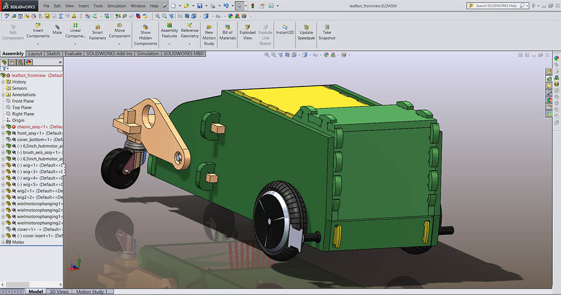
In week Week14 I started to make the first mold for the cover of the LeafBot. To fixate the cover and be able to open the cover, I decided to lengten the axles of the tilting storage volume and use these also for the fixation of the cover. On the left side the cover insert is visible and on the right side without the insert.
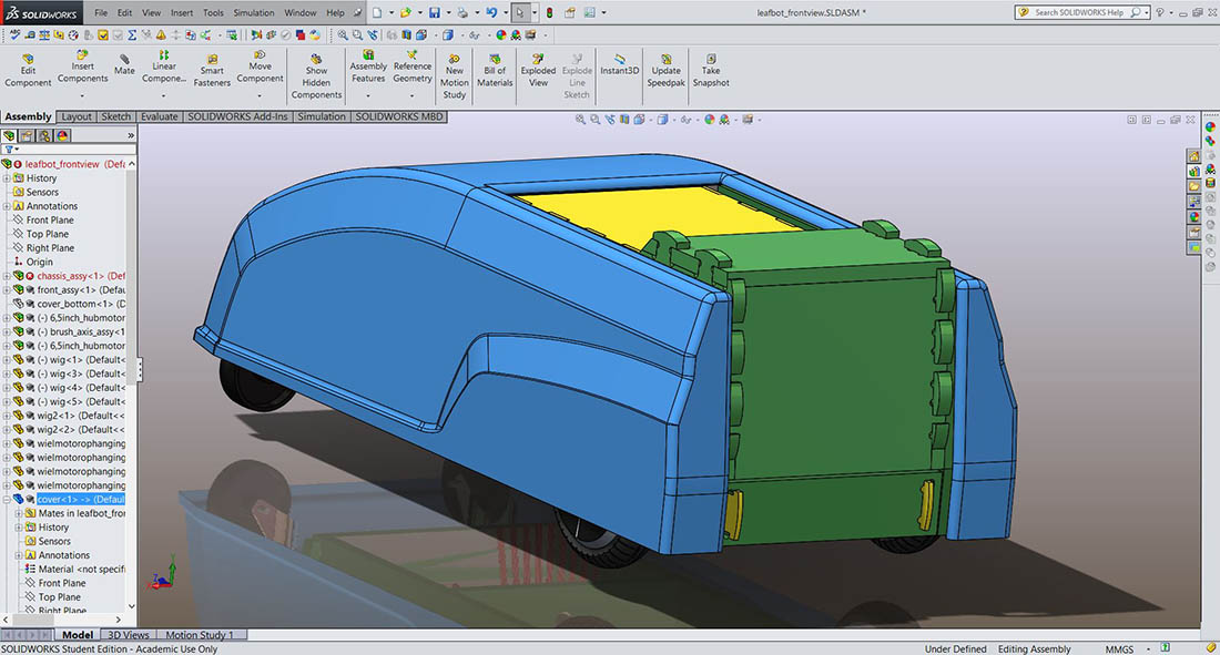
In this picture the cover is mounted on the leafbot.
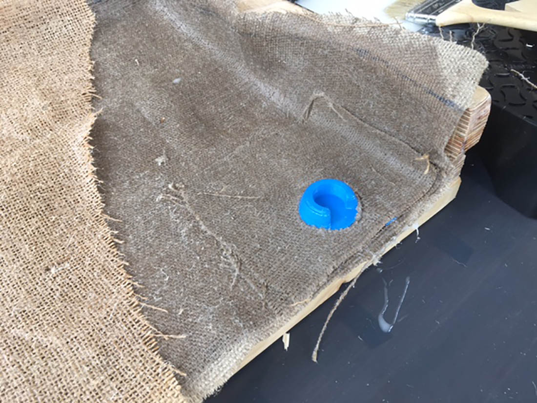
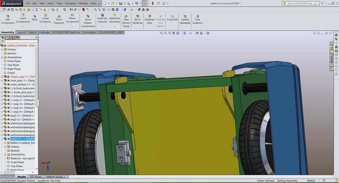
Detailed view how the cover is fixated to the 3D printed axles. The inserts are laminated in the composite.
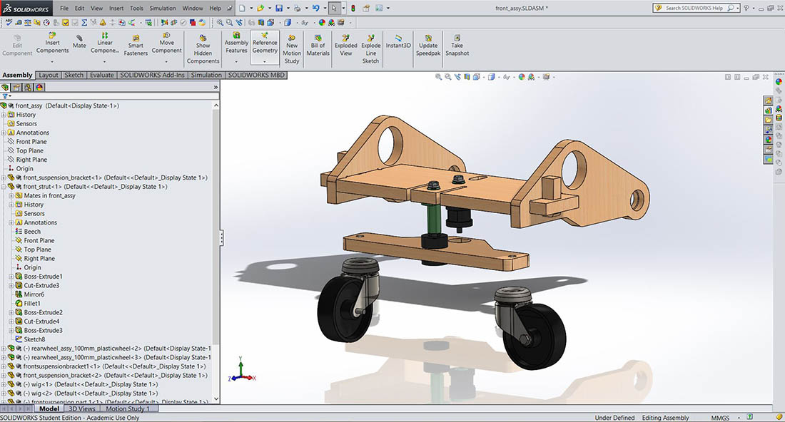
In Week12 I casted an rubber bracket part to connect the front wheels to the frontsuspension. But the design was not ok. I had to design a new different design for it. The design consist out of a 3D printed axle that is fixed in the hole of the frontsuspension. Over this axle a casted rubber part is placed, where the wooden bracket, thats holding the frontwheels, is clamped over it. A M8 bolt and nut is fixating all the frontsuspension parts. To prevent that the frontwheels are pushed backwards and or turned, a second rubber suspension part is added.
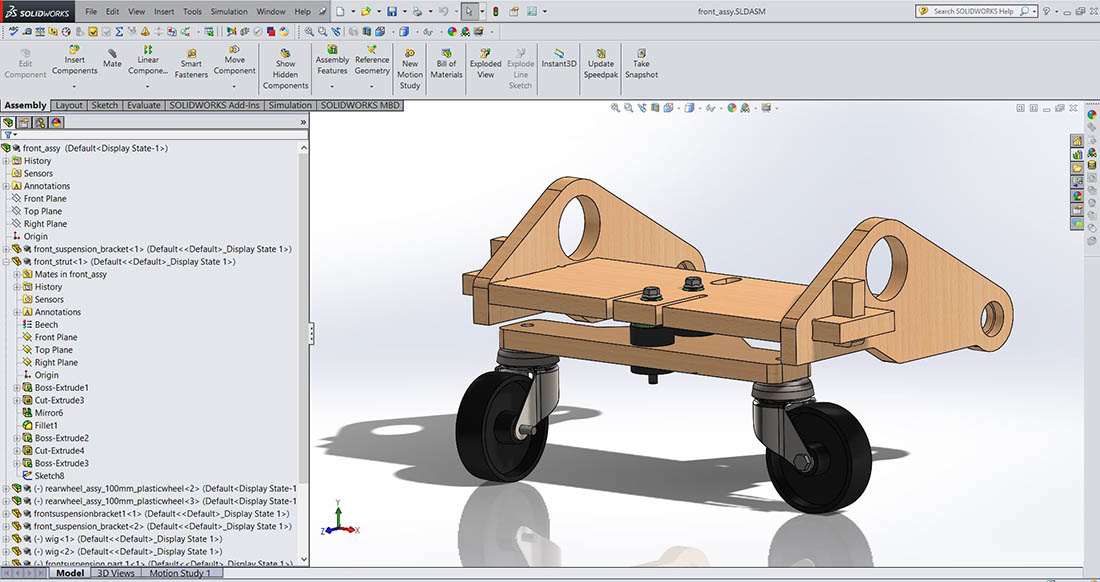
An exploded view of the new construction.
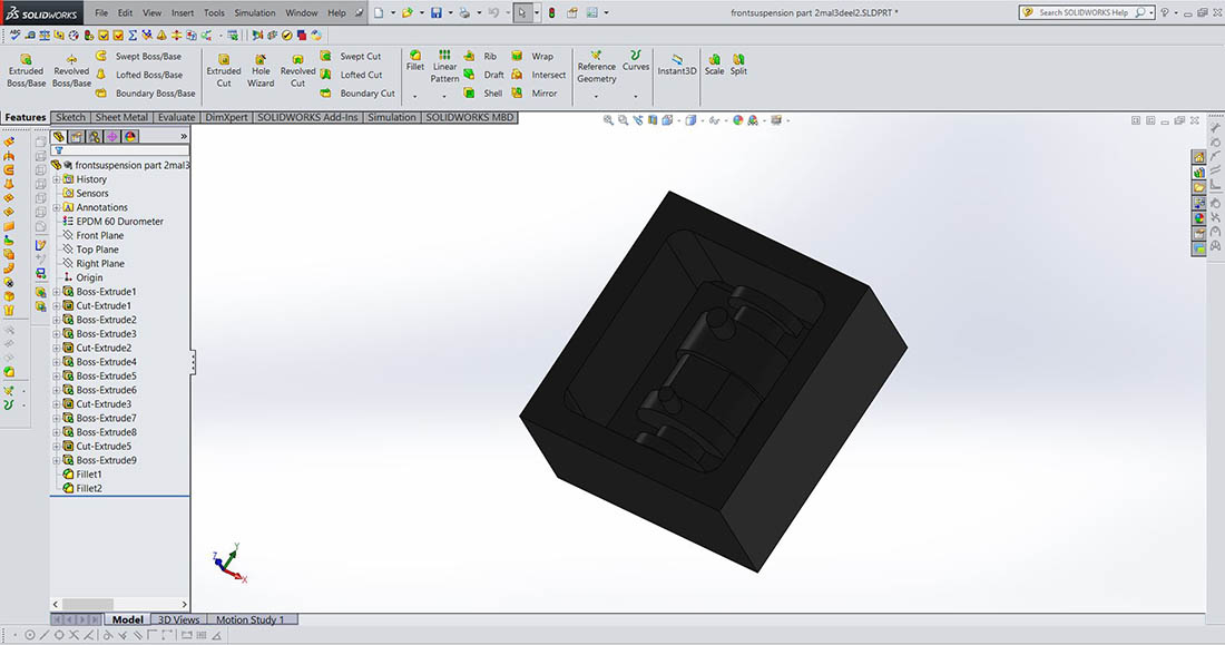
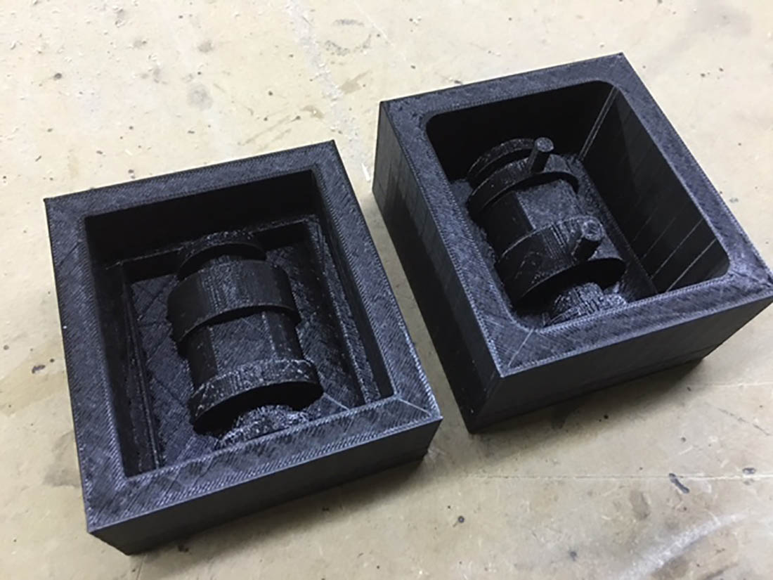
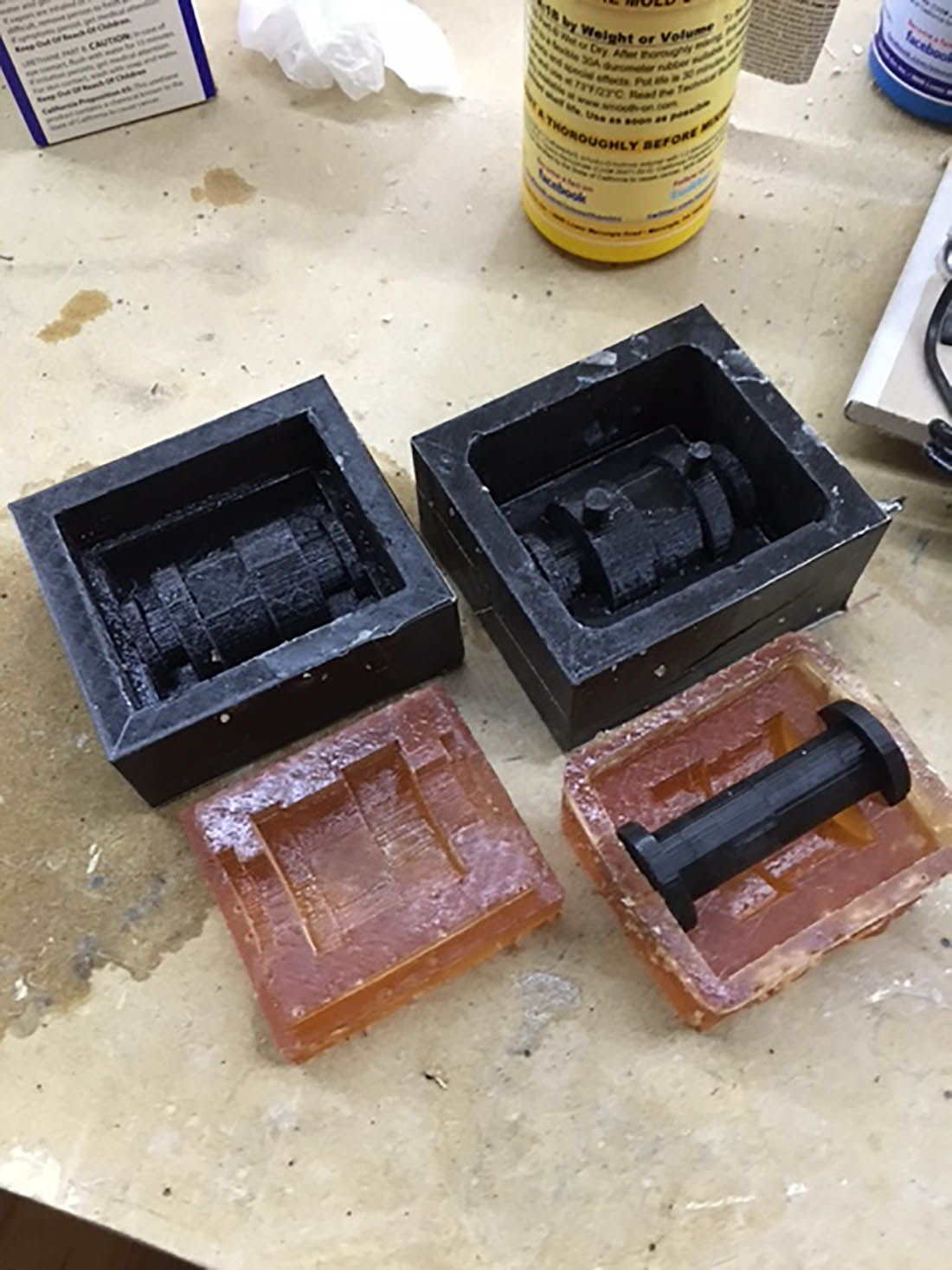
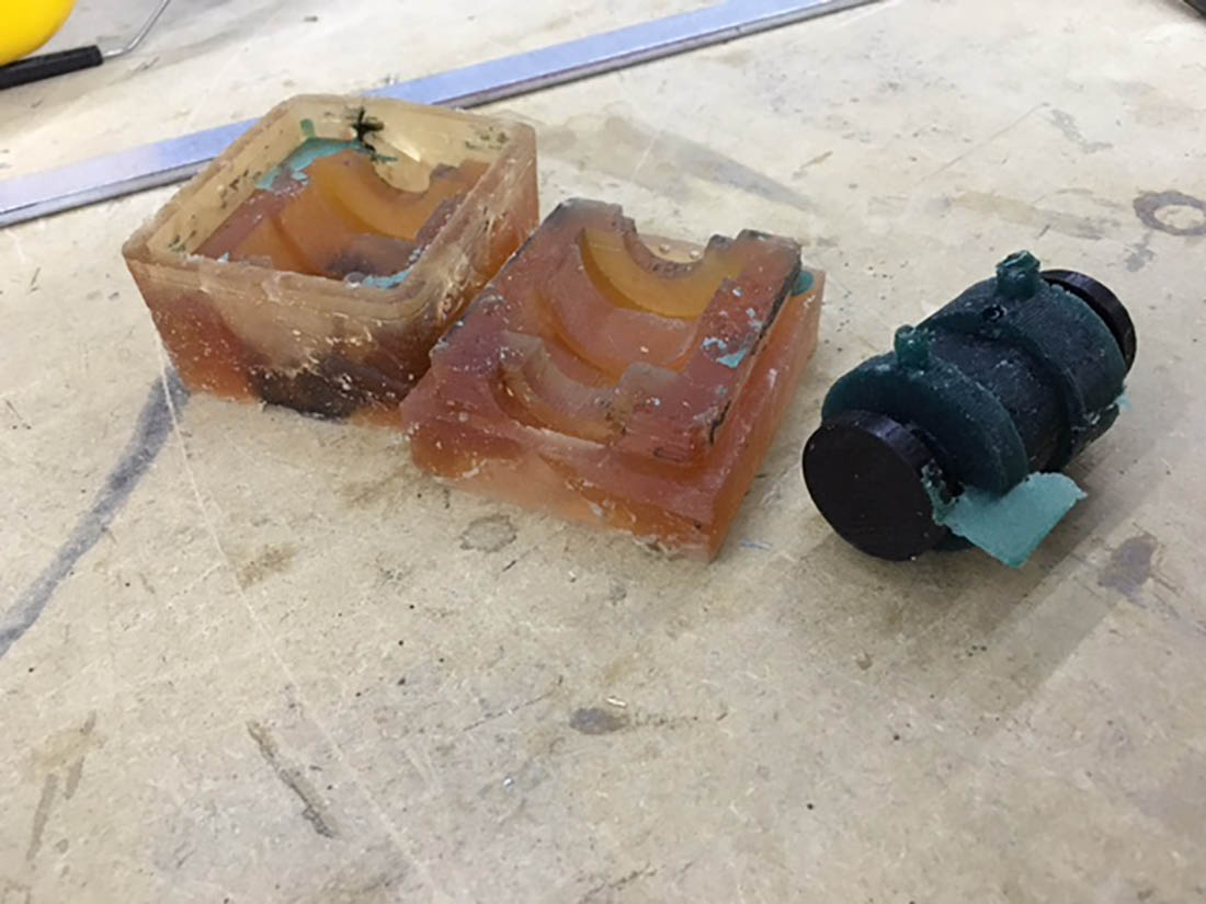
The green axle, see picture above, is been cut in two halfs. Then for each half I created an small box and one of the molds is applied with the filling and draining canals. Also in this mold the insert, to form the hollow inside, is added. This insert is also printed separtly.
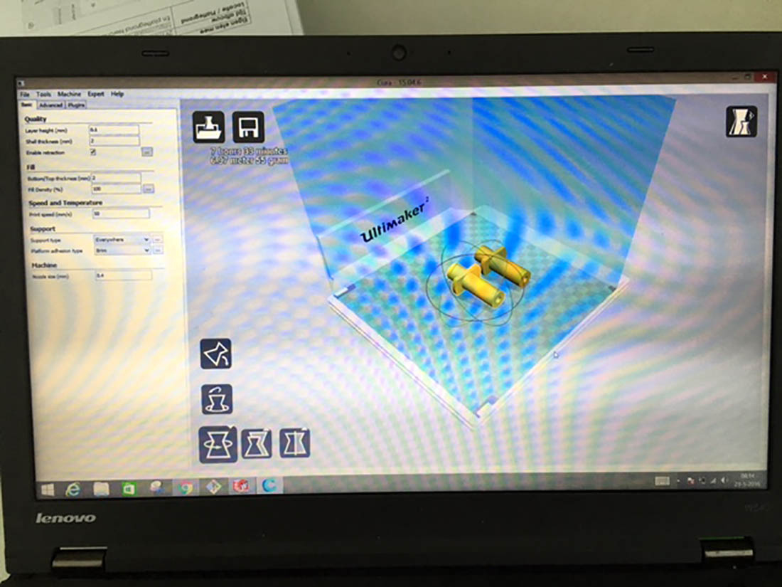
On the Ultimaker 2 the mold was printed with fast printing setting. The layer thickness is 0,3 mm. The infill 15%. With these setting I was able to print the 2 molds within 8 hours, to be able to cast at home. It was already Friday and in the weekends the FablabEnschede is closed. And I needed the weekend to for casting, otherwise I would not be able to finish the parts on time.
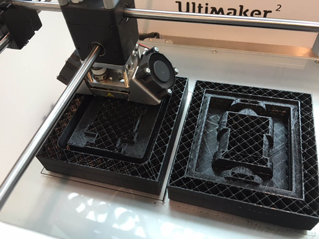
Just before closing time the molds where finished. The thicker layersettings is good visible.
Because of an curing time of 16 hours, I had to cast the silicone mold on Friday evening. I used Smooth-on PMC121/30. I mixed it carefully and slowly. Because of the fast printing speed I noticed a lot of gabs in the printing surface. For this reason I applied tape around the mold to prevent a lot of silicone would drip out of the mold.
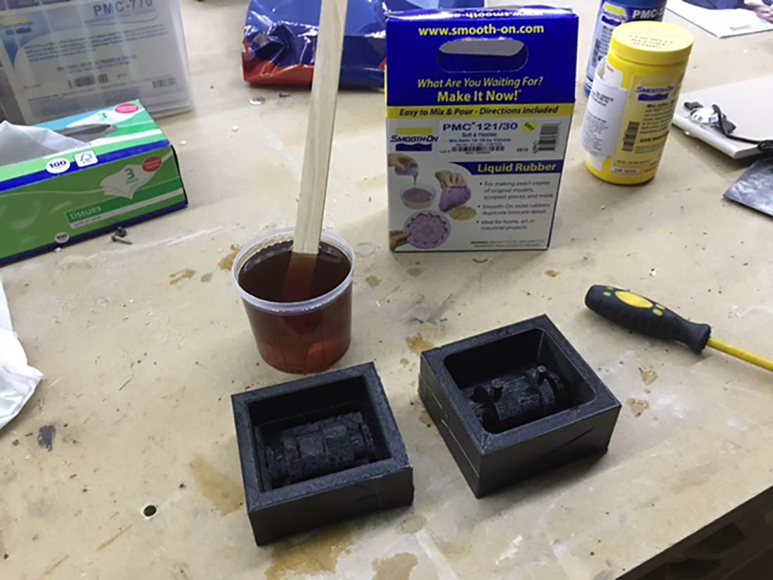
The silicone resin was casted in the mold. I tried to cast it from an higher position, and making sure the beam was as thin as possible, to "break out" the air bubbles.
But I noticed that there where still a lot of air bubbles at the positioning where the resin casted in to the mold. With an Fein Multimaster I tried to fibrate the air bubbles out of the resin, but it was not so succesfull. Next time I will try it with an vacuum camber. I did a try with an vacuum cleaner, but the plastic mixing cup pulled together.
Saterday at 13 PM I released the mold. It released well. I tried to fit the 3D printed insert and that fitted perfect. Good to see I created addition edges around the silicone mold. When put on top of each other the 2 silicone molds are guided and close to prevent resin will come out of the mold.
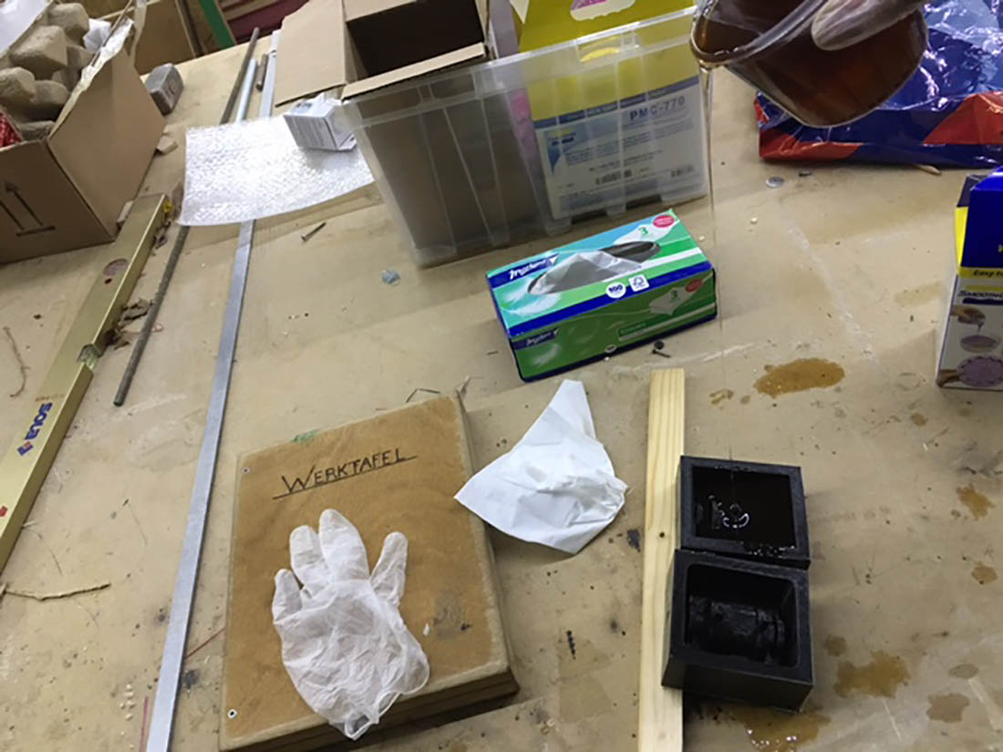
Next is vaseline the molds and insert to make it ready for casting the PU rubber.
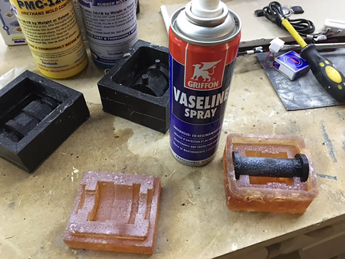
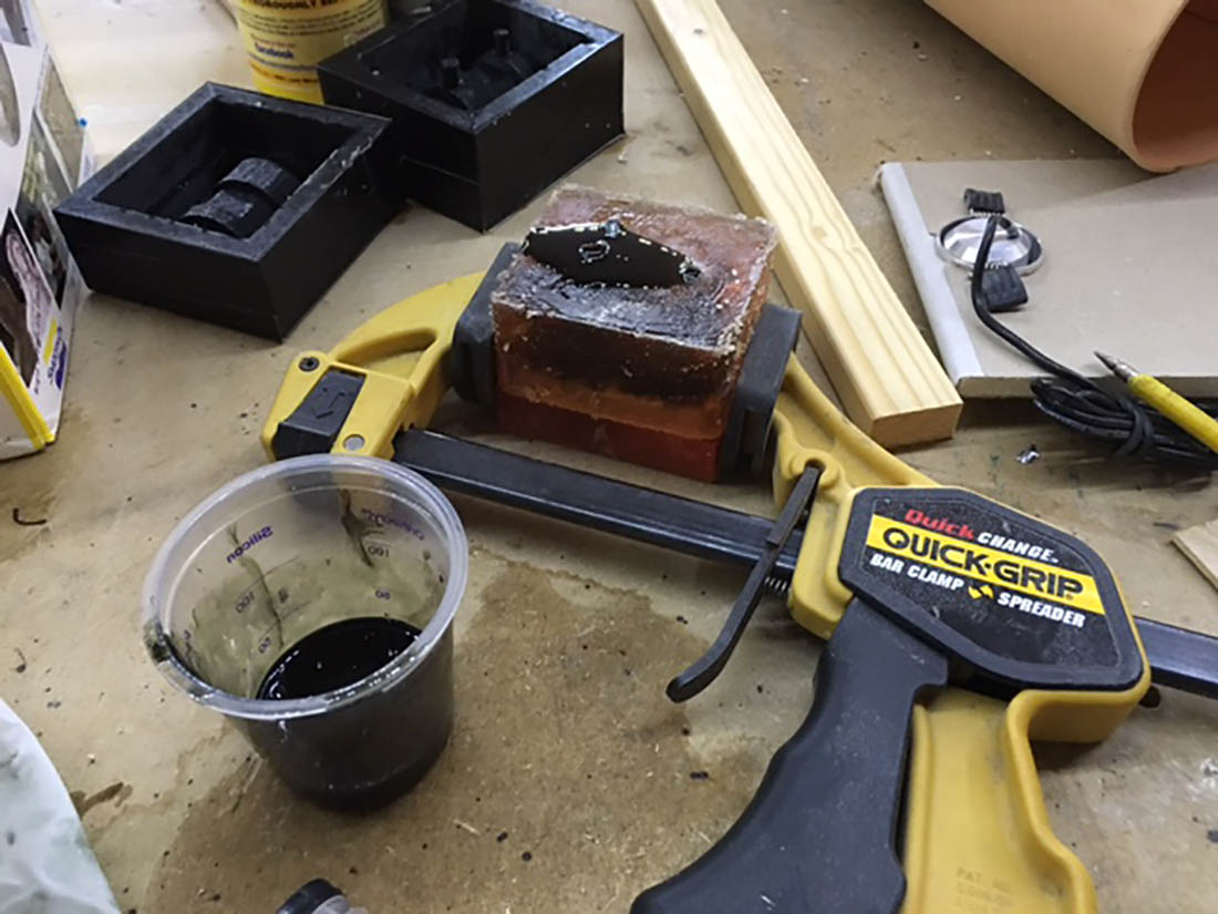
I closed the mold and angled it a bit. The injection opening positioned to the lowest side.
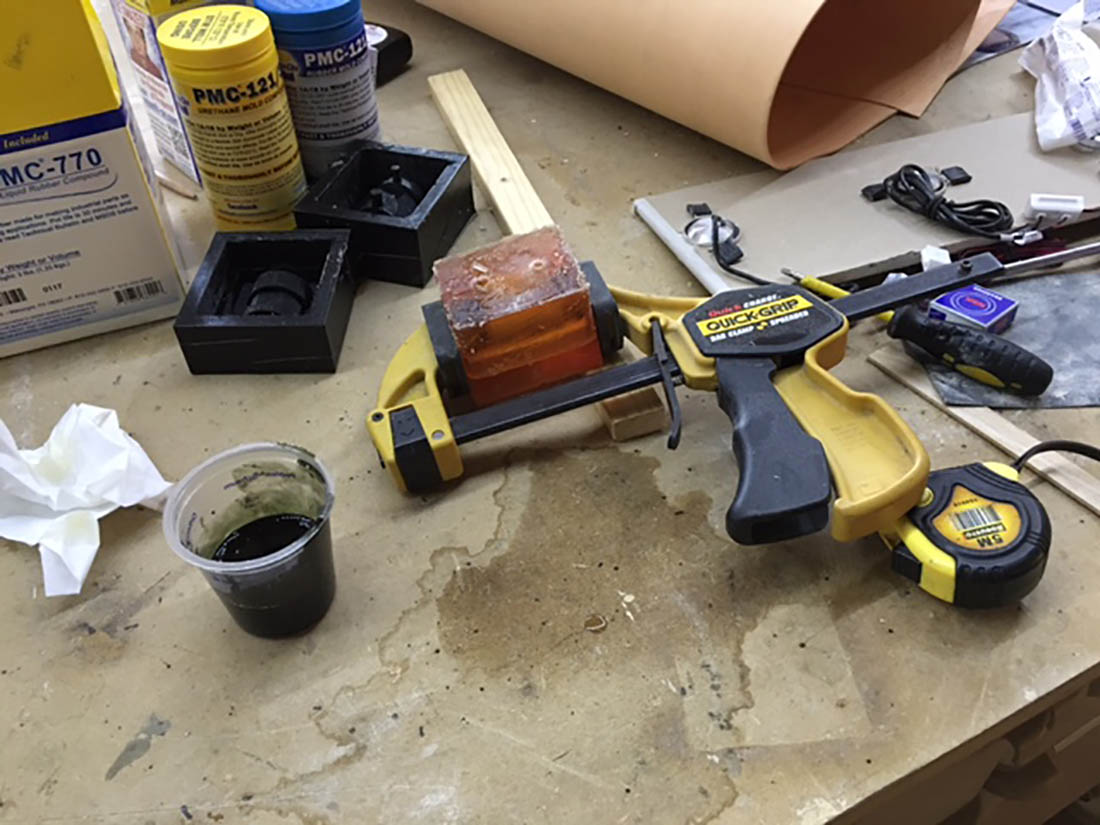
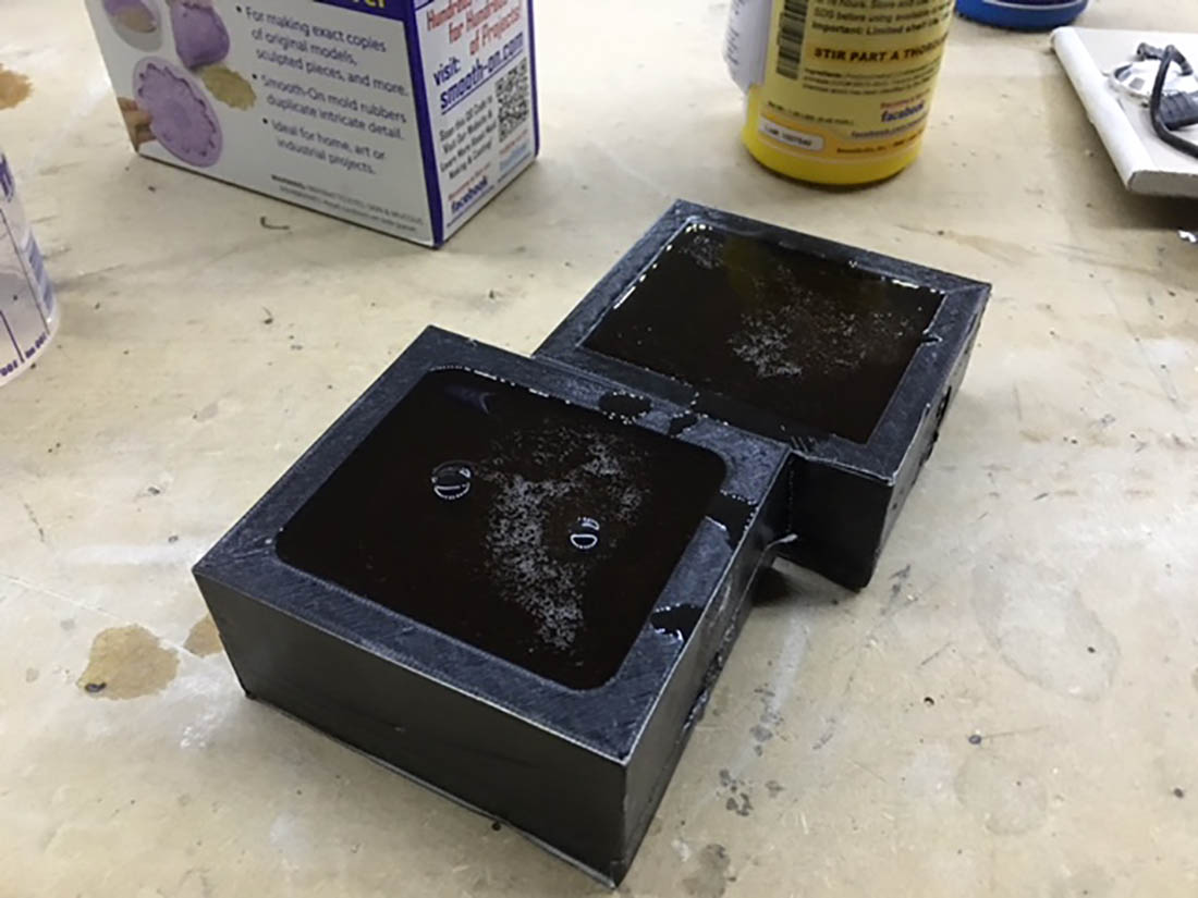
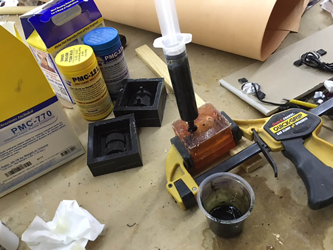
The PMC 121 resin, the same I used in Week12, is mixed. For the first one I mixed black paint in to the resin. With a squirt I injected the PU resin slowly in the mold, untill I drained out of the air escape hole.
I took the mold of the wooden support.
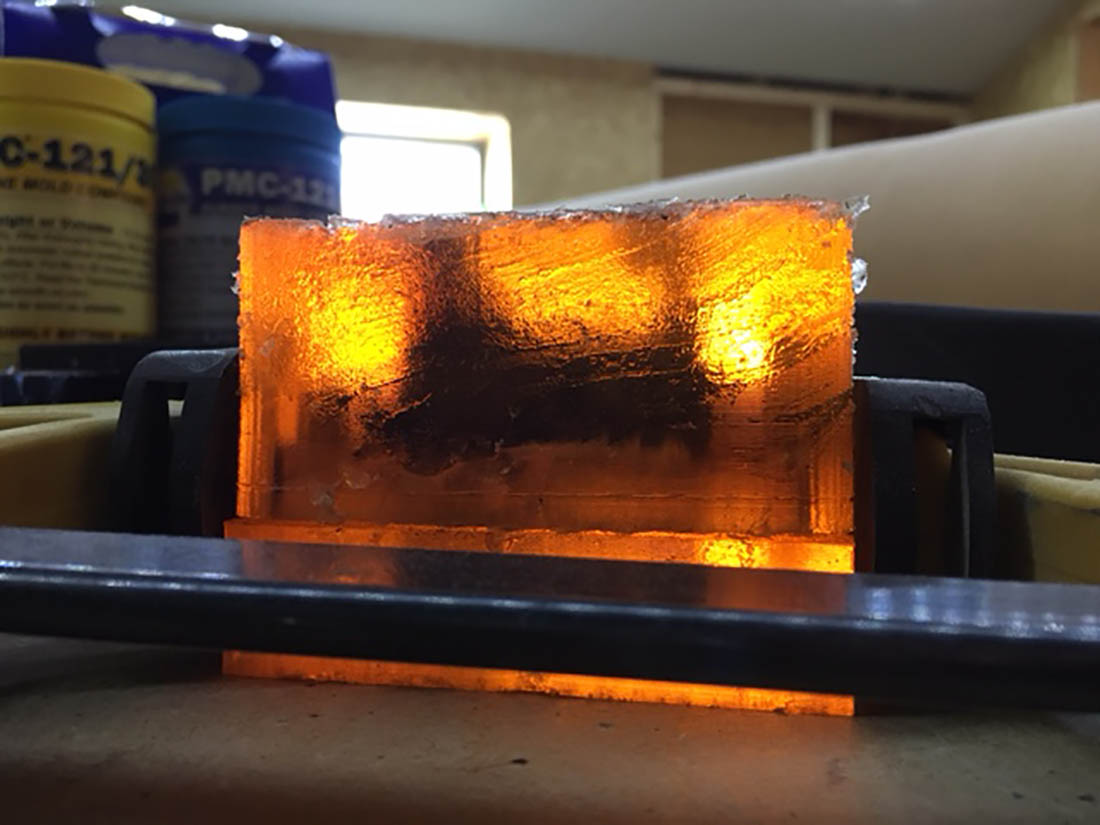
I could see that the mold was filled ok.
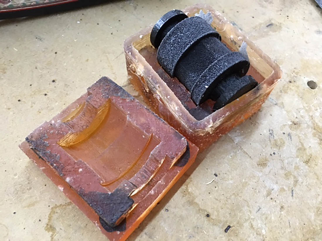
On sunday morning I could easely release the mold and takeout the rubber suspension part. Not much resin was slipped trough the two mold halfs.
The rubber suspension part fully released from the mold.
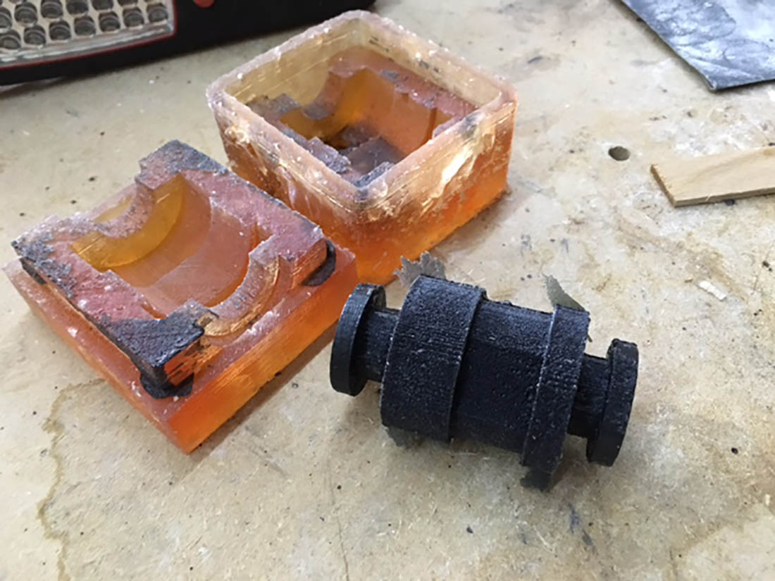
I created an insert that is separatable otherwise the it will be very difficult to get the insert out of the rubber suspension part.
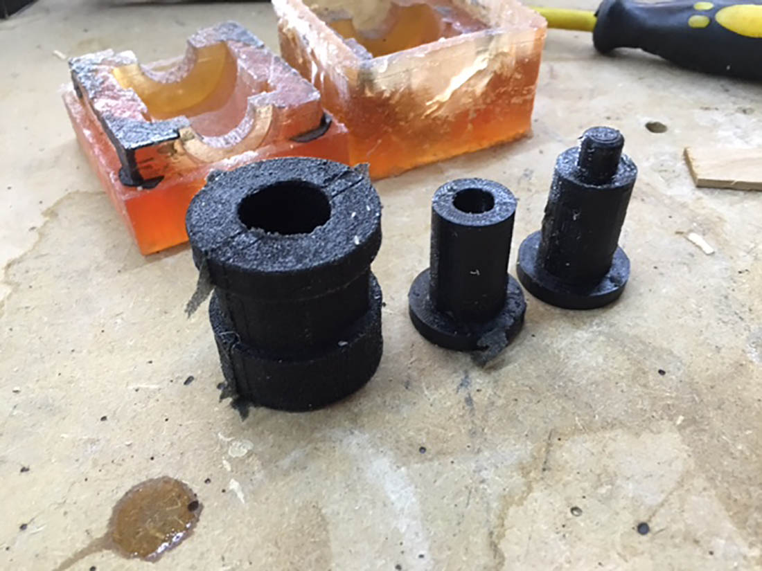
The white axles where also printed very fast, but they could only be used to do an assembly check. They where to fragile to be used in the LeafBot.
It fitted perfectly.
The second rubber suspension part could now also be casted. Sunday evening it was also ready. I coloured this one green. On both rubber suspension parts I had an small round air bubble on the part, just above the injection point. I think I should have placed the injection point a bit higher on the spot where the air bubble was not able to escape.
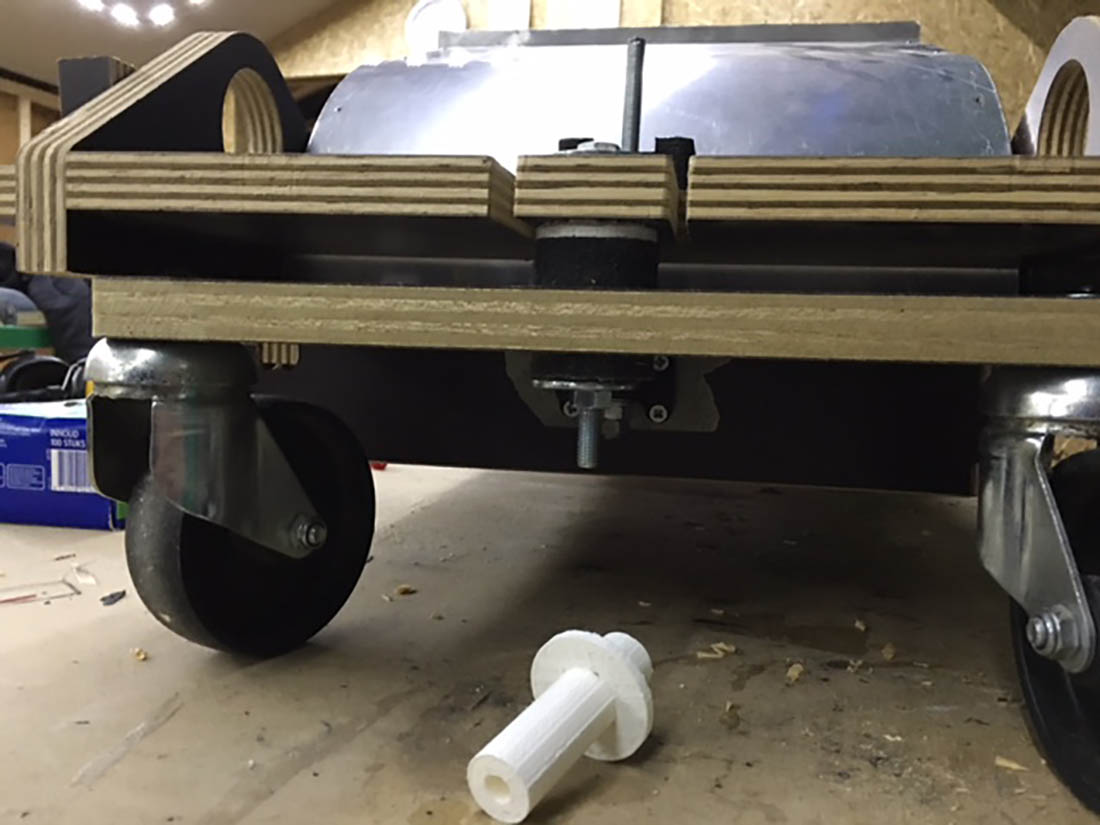
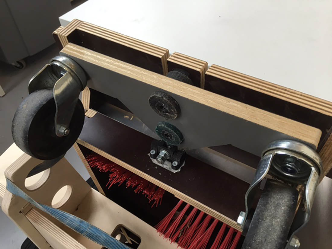
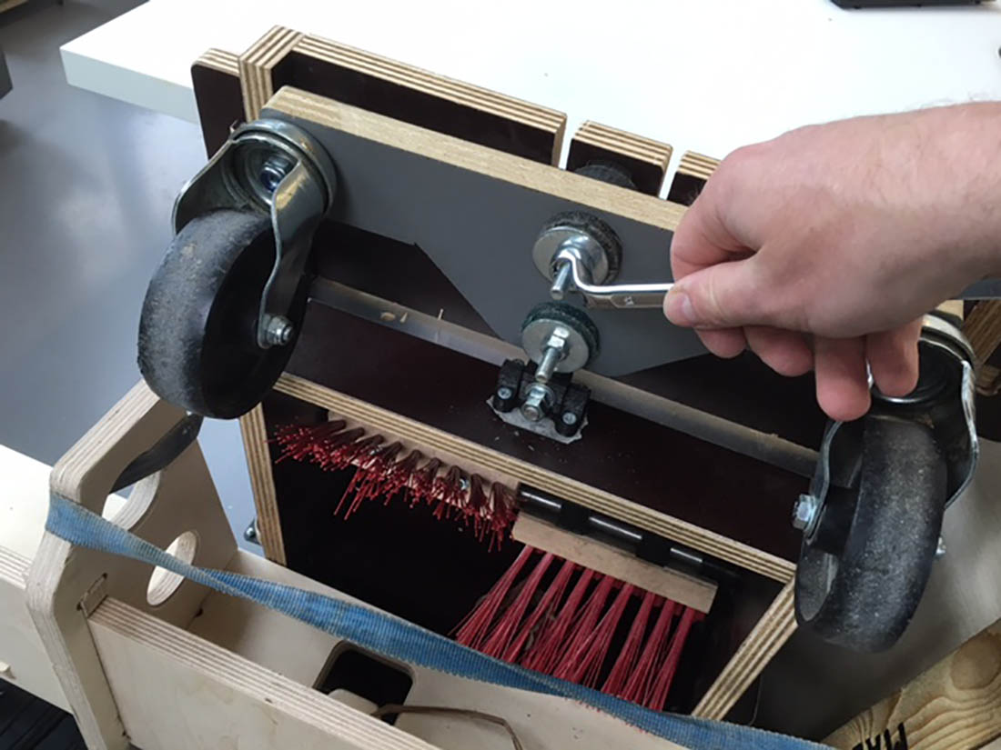
To be able to fix the new rubber suspension, I had to make an new wooden wheel support with I made also at home from concrete plywood leftovers. I drilled the holes in the frontsuspension to be able to assemble the 3D printed axles and to fixate the front wheels in the wooden wheel support.
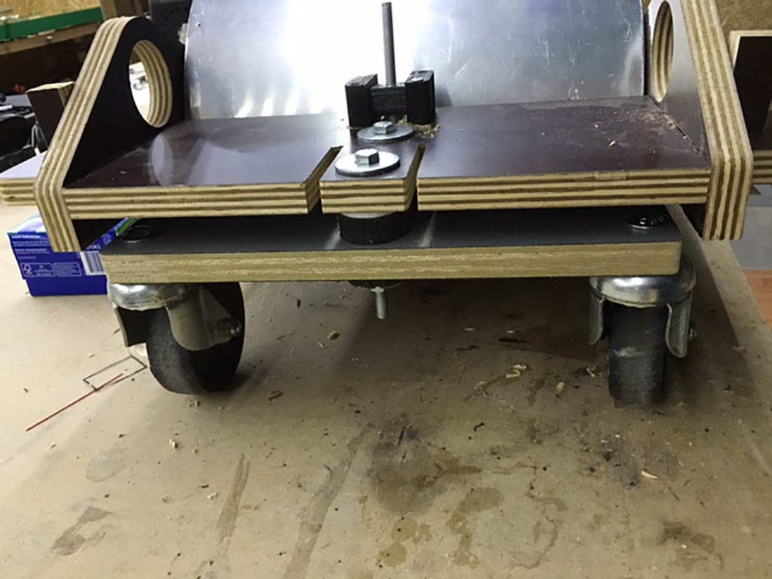
This is where I had to make the rubber suspension parts for. The wheels should be able to tilt a bit to follow the bumps in the garden.
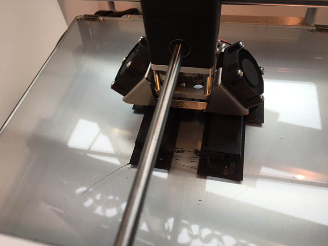
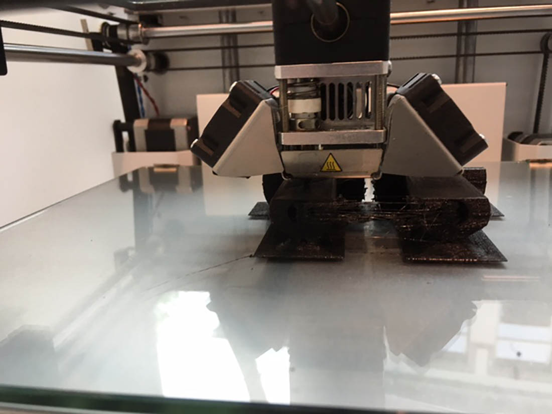
The axles had to be printed again. Now with maxium filling and 0,1 mm layer tickness. It took 7,5 hours to print them, but they are very stiff and strong.
A picture during the printing. Good to see that the filling is 100%. After finishing the printing proces I noticed that the axle where not perfectly round. They seemed to be collapsed a bit. Perhaps due to the increased printing temperature. The ultimake had troubles with this PLA filament and it was constantly blocked. I increased the temp from 220°C to 230°C. After this change the printer worked fine, but perhaps the PLA was a bit to soft that it collapsed for this reason.
In this picture the oval shape can be seen. It should be printed round.
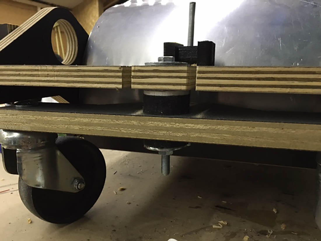
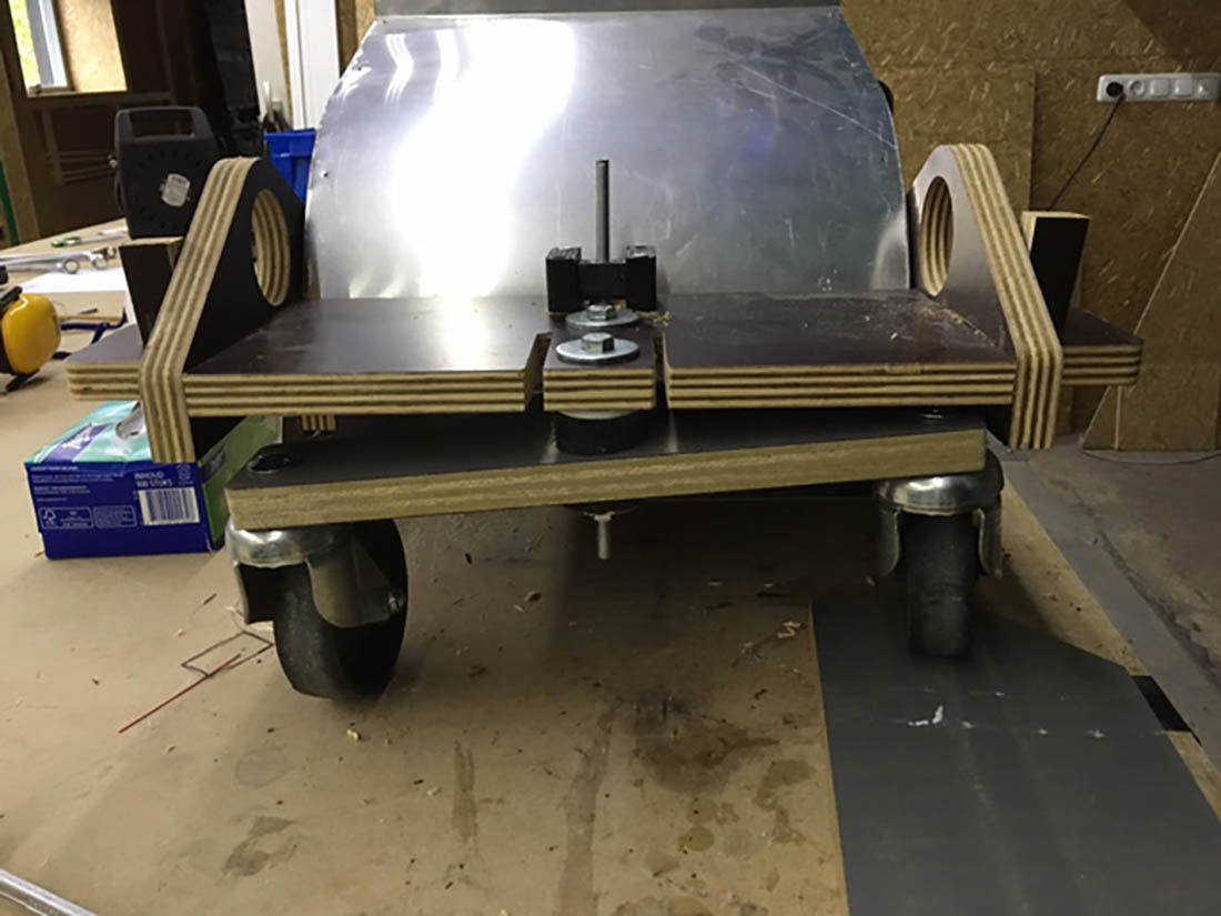
Final assembly on Tuesday with the new axles.
Perfect fit and the construction is much stiffer then with the white axles.
Assembly movie of the front rubber suspension part
SolidWorks parts of the mold + inserts and casted part