Concept development
website version1.0
First thing was to analyse current lawn sweepers that can be town behind a tractor. They come in several widths. They wipe the leafs with a brush. This brush is divided in 4 brushes fixated

On a rotating axle. A set of 2 brushes are mounted 180° from each other and the other pair of brushes are mounted 90° from the other pair on to the axle. By doing so, the resistance from the
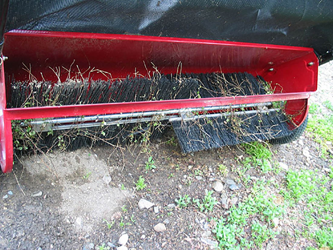
brushes that slide trough the grass, is 50% less. Because of the leaf sweepers is been town by a tractor the wheels are forced to rotate. These wheels are connected by a gear wheels to the axle
of the brushes. The faster the tractor is driving, faster the brushes starting to rotate.
But in this configuration the brushes are always rotating when the leaf sweeper is been moved. To prevent that the brushed sliding too deep through the grass, and building up to much
resistance, the height of the brushes is adjustable.
Next thing to do is to decide which parts be used for the leafbot. Standard brushes for a leaf sweeper costing about €80,-. Both locally shopped or at Amazon . Pretty expensive and far too wide
to fit in the leafbot. But the local toolshop could help me. Bricklayers using special small brushes with only 2 rows of Nylons hairs. Four of them costing only €8,95, locally made, and
equipped with long hairs, it can slide easily through the grass and can pick up more leafs at once. These bricklayer brushes are the starting point of the 3D cad design work. They depend the
size of the leafbot.
Analysing the leaf sweepers I notices that the length of the nylons hairs are about 10 cm. The bricklayer brush hair length is with 11 cm, with is similar. Since the bricklayer brushes are made of wood, I had to design a different connection system to fix the brushes on an axle. I made a design out of a metal strips that comes in a standard size (wxh) 40x4 mm. The brushes are then mounted with screws in pairs on the axle.


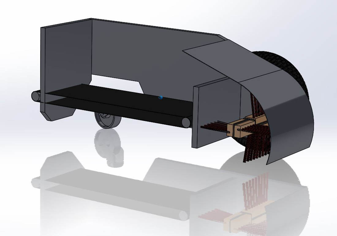
After analysing the shape of an afri-fab leaf sweeper housing, I started to design the bended metal cover. I designed it out of metal because leafs will slide against it when they are been
pushed upwards by the fast rotating brushes.
Next thing was to decide which tyres to be used. Looking at home in one of the barns the wheels of a wheelbarrow suited me. The come in 13” size which is about 310 mm in diameter.
Solidwork is the 3D software that is been used in the FabLabEnschede. I started working there in 2015. I was used to work with Solid Edge and NX, but SolidWorks was new for me. So there
is still a lot the learn for me to work with SolidWorks. In the process of the design of the leafbot, I tried several new features and possibilities. Making a tyre tread pattern was new
for me. So during the concept decision phase I made several 3D cad models of different tyre models and sizes.
The first parts, that are mention above, have been used to build up the first assembly of the leafbot.
First a configuration with 2 separate driven wheels and 1 wheel that follows, using 3 the same 13”wheels, was made. With this design the frontwheels do not need an steering mechanism.
The 3 wheels do not need a special suspension system to keep al wheel to the ground when driving over a bumpy lawn. Out of 18 mm plywood a wooden chassis was created. This chassis
can be milled on the Shopbot milling machine. Analysing this concept it proves that the rear wheel uses about the half off the total leafbot length for turning the wheel, when cornering.
So this design was not feasible to me.

Rear wheel positioned backwards
Rear wheel positioned to the front
Concept 2 the design and position of the wheels is completely changed. The leaf storage volume was doubled with the same length as concept 1. Now two wheels where located at one side and 1 in the middle of the others wheels on the other side. With this configuration the leafbot can also turn sharp around a corner. To do so the big 13inch wheels needing a lot of space to turn the wheels. This results in an very wide leafbot which is not the goal of this project. The wider the leafbot will be, the harder it gets to drive through the bushes. For the steerable wheels a steering system has to be designed and build. But the front and rear wheel steering system can be the same.

Concept 3 was an evolution of concept 2. Now equipped with 4 13inch wheels the leafbot has more stability. But this configuration is even wider then concept 3. And a Ackerman steering system has the be used, making is more complex and more costly to develop.
Concept 4 had to go back to the original idea to use 2 separate driven front wheels. But it needed smaller rear wheels. I noticed already that Robot mowers also use big wheels for driving the robot, and much smaller steerable wheels to support the robot. First I looked to wheelchair wheels on the internet. After a search, 6inch wheelchair with turn able fork looked ok
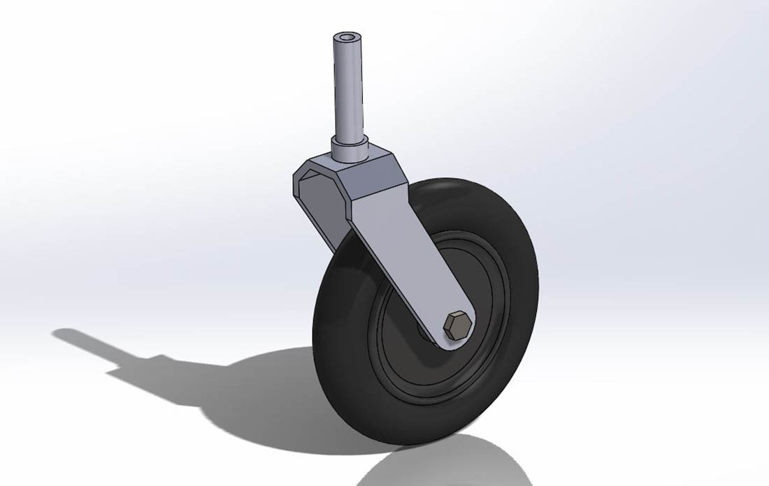
to me. With the dimensions found in the internet I build the wheels in SolidWorks. Since the wheels have an outside diameter of 12.5 cm they still need a lot of turning space and also the bottom of the chassis raised upwards, reducing the storage volume. The wheels had to smaller than this. The robot mowers use very small wheels. So I had a look in my barn and found 2x 100mm turn able wheels. I tested the wheels by driving them on the lawn. This looked promising and if
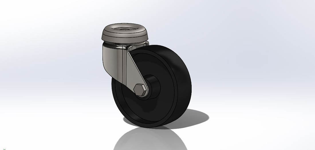
the weight of the leafbot isn’t getting to heavy, this should then not be a problem. So the design of the chassis was changed again. Also these nylon 100mm wheels, with metal turnable fork, where build in Solidworks. With the possibility to unload the leaf on the back an unloading mechanisme had to be designed. The idea is to drive backwards to a sucking mechanism and then suck the leafs out of the leafbot. But this takes a lot of sucking power to suck the leafs out of the leafbot. A bottomplate that is replaced by a driving belt can move the leaves
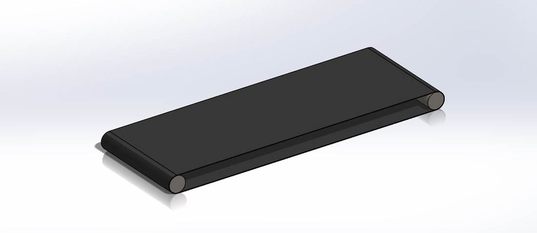
to the backside of the storage volume. Together with the sucking mechanism all the leafs should then be able to taken out of the storage volume of the leafbot. Looking again on the internet
for possible options for a drivebeld, I decided to make a belt form a innertube of a car of motorbike. This is cheap and should be strong enough. By using a innertube a wide belt can be
created. Also these parts where build in SolidWorks
The search for electric motors, to drive the wheels of the leafbot, was done at Alibaba. The amount of electric motors is enormous and my knowledge of it to make a choice to little. My
goal was also to find a cheap motor. After a long search, the motors of a self-balancing skateboard came across. This is exactly what type of system I was looking for. Steering by
independent wheel speed is the system I like to use. I searched for bigger wheels and found 10-inch-brushless-wheelbarrow-hub-motor
These wheels are a little bit smaller in diameter then the wheelbarrow wheels but I do not think this is a problem. What was a problem how to build them in to the chassis. The axle of the wheels where interfering with the brushes. I did not want to move the front wheels too much to back, because then the front of the leafbot can easily be stuck on an object.
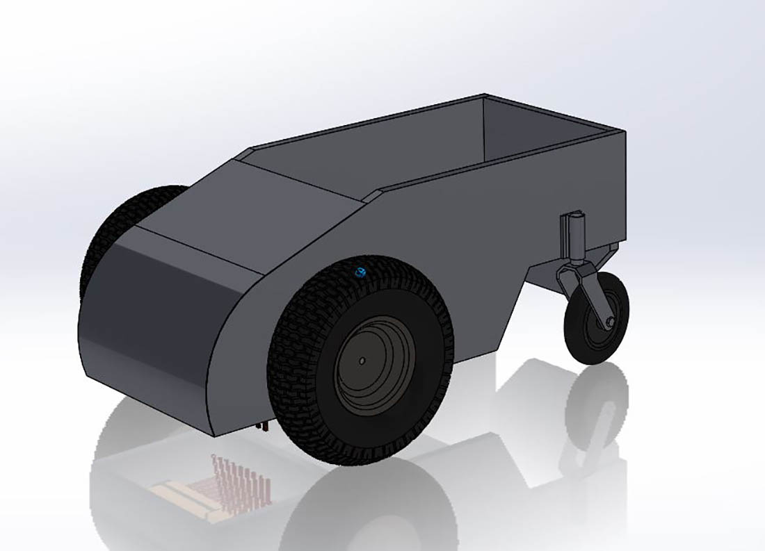

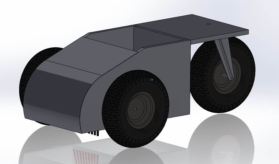
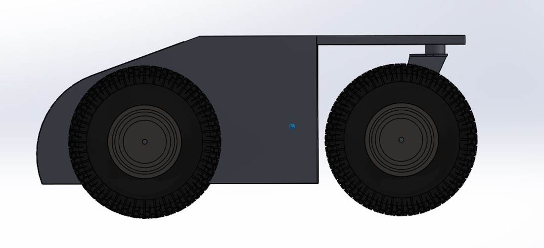
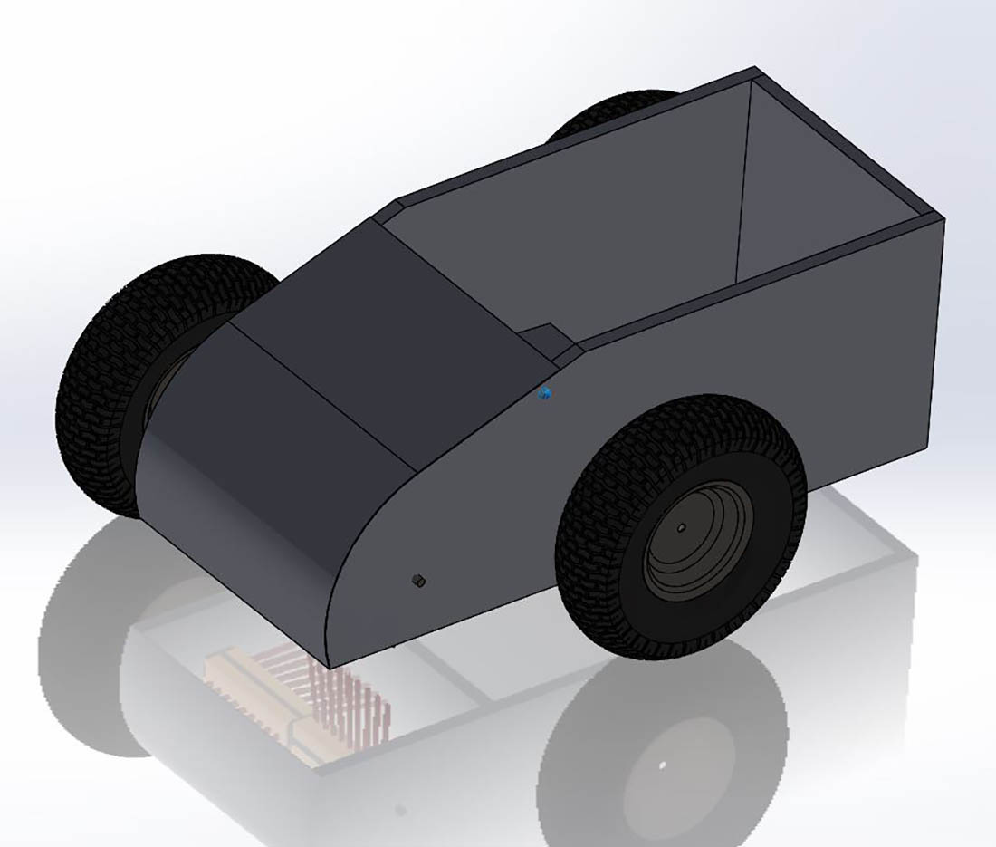
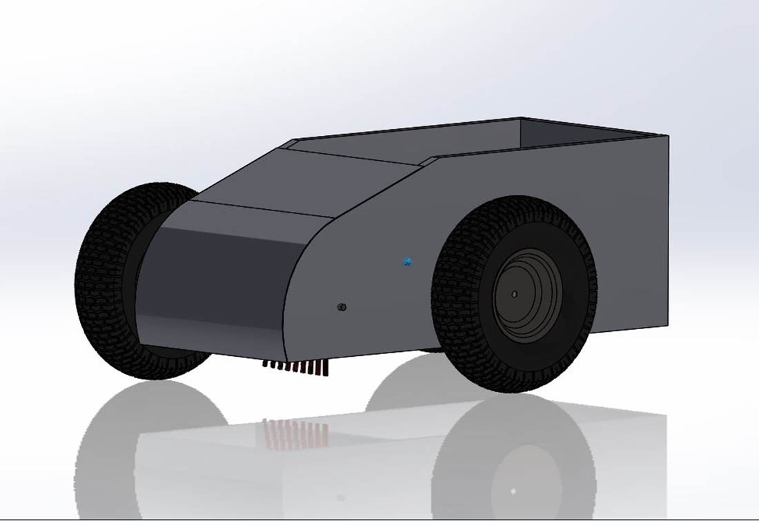
Concept 5 was then made after a long thinking process. A had to move the big wheels to the back of the chassis, making it possible the place them nearer to the chassis. The smaller wheels where places in front of the leafbot, reducing the width of the leafbot. Also this give the opportunity to design a self-alignment system to keep al wheels toughing the ground when driving over a bumpy lawn. Also a important reason to place the smaller wheels in front is that when entering a sharp corner, concept 4 swings the back of the leafbot to the outside, bumping in to a obstacle. With the steering wheels at the front, the front side is been pushes into the corner. I noticed this looking to the lawn mower robots.
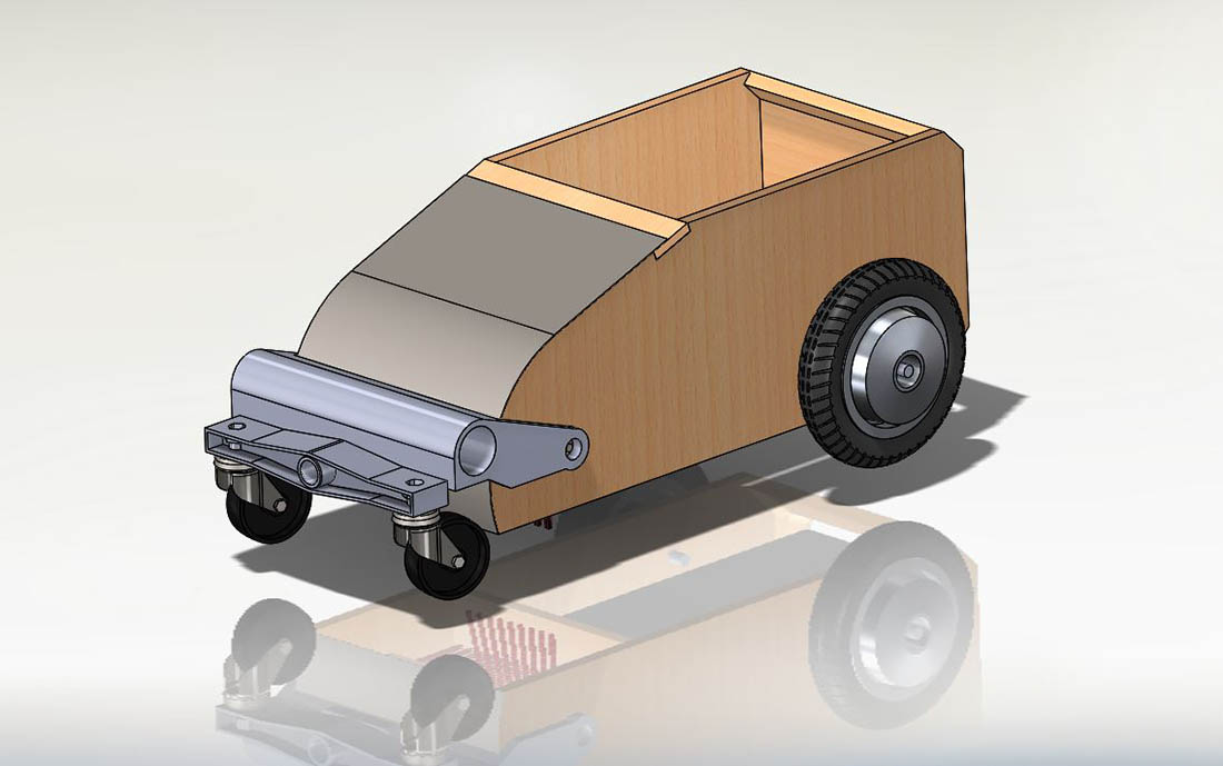

I designed a front suspension system in solidWorks and intergrade the electric motor which drives the axle of the brushes. Also it is now possible to intergrade a levelling system to adjust the ride height. I made a first design to be made with SLS 3D printing technic. The hole front suspension system can be printed as 1 object. When I have found a suitable electric motor to drive the brushes I can finalise the design of the front suspension.
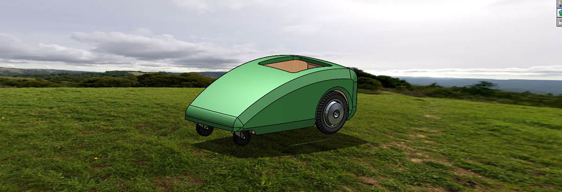
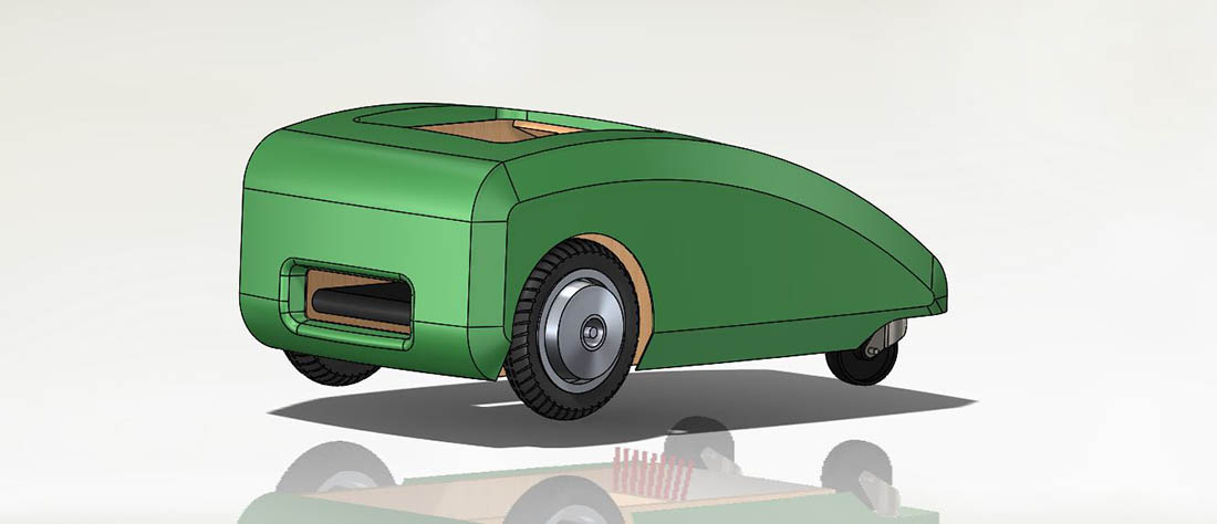
With the concept fixed, I started to design the body work. This part I like to build in the week where we have to make parts with molding and casting. The design is made sleek so the robot does not get stacked behind something easily. Also at the left and right side of the chassis I created space to fit the electric controls and batteries.

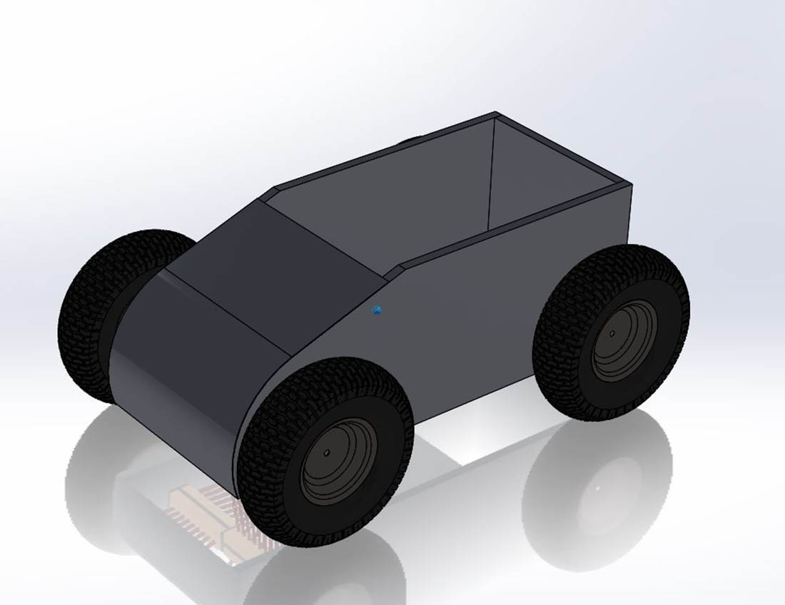
The build of the 3D SolidWorks leafbot model is done by making first separate parts and make then part assemblies. Out of off the separate part assemblies I made bigger groups of parts.
Like the front suspension is one bigger assembly. The wooden chassis, with contains several wooden parts, is one bigger assembly. All the movable parts have been mated so that they can
turn or move in the total assembly. This is done to be able to check if the parts fit in all positions in the body of the leafbot and to be able to make nice renderings.
I started by making a rendering in SolidWorks.