Sander van Vliet
Fabacademy2016
@Fablab Amsterdam
Development process of:
a window control / ventilation system responding to CO2 levels (prototype)
 See the description of the initial idea on the page of the first week.
Final Project Presentation
On 15 june 2016 we presented our Final Projects to Neil and all other Fablabs and students who joined the session that day. The video on the left was recorded on the video conferencing system that was used throughout the Fabacademy course. The video on the right is the presentation video I had to make as part of my documentation.
|
|
Here is an article on the Fabacademy final presentations 2016 published on the Waag's blog.
Overview of components
The system consists of two parts which will be communicating with each other:
A wall panel containing a main microcontroller board, a wifi board, the CO2 sensor and breakout board, an LCD and an external power supply.
A window mounted casing containing a main microcontroller board, a motor driver board, a wifi board and an external power supply. And close to it two mounts which hold the motor that will operate the window by moving a mechanical part.
Fabrication process of components
Below you can see how I made it. Scroll down to see it all or use the links to navigate to specific components.
A panel for the display and sensor
Rear part of the panel
Window frame model for testing mechanics
Output device: Testing with a stepper motor
Stepper motor with leadscrew and leadscrew nut
Testing mechanism and leadscrew stepper motor
Mounting the motor and the screw
Casing for electronics
Cover
Input device: a CO2 sensor
Microcontroller board to control the motor
Motor driver board
Wires overheating!
Voltage regulator boards
Schematics
Networking
Code
Putting it all together
Ideas for improvement
The last day of Fabacademy 2016 and credits!
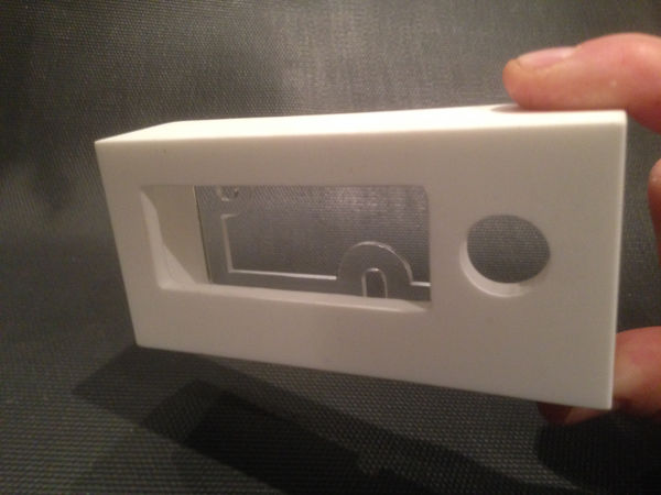
A panel for the display and sensor
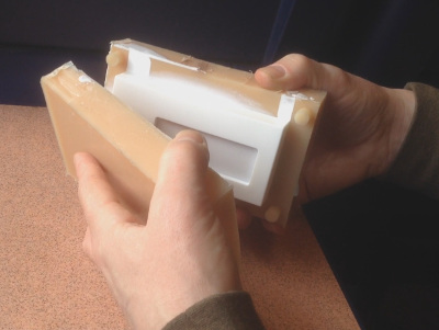
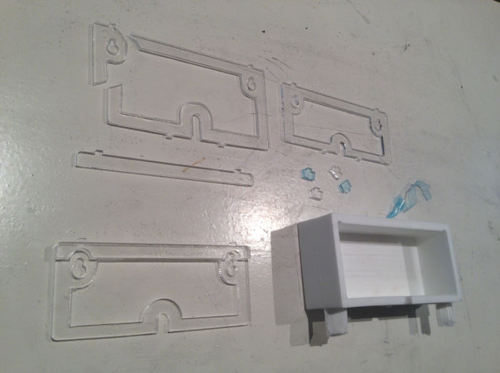
During the Molding and Casting week I created a panel which will be holding the CO2 sensor and will have an LCD (display) which shows the current CO2 value. Here you see the panel coming out of the rubber mold.
At this point I noticed that the openings were not formed because I had put too little pressure on them and the material had found its way in between the rubber mold parts where the openings should have been. You can also see the flashing at the parting line; material came through at the line where the two mold parts met.
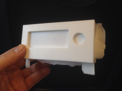
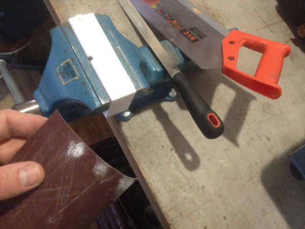
I used a file and sandpaper to remove the flashing and I was surprised how smooth the surface of the Smoothcast 305 white plastic became!
I also removed the thin bits that had closed the openings and I was happy with the looks of the panel!
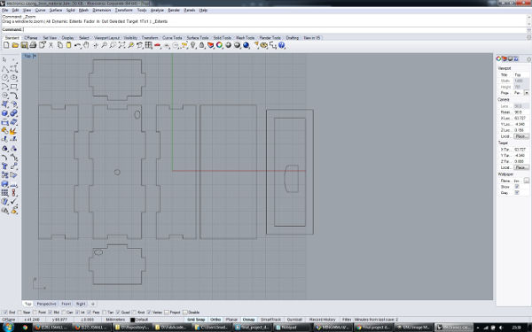
Rear part of the panel
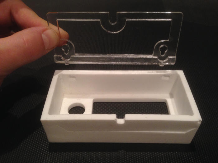
I wanted to be able to hang the panel on the wall, but I did not take the time to think about a mounting system when designing the mold (of the mold) of the panel.
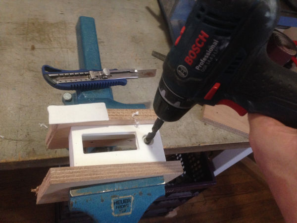
I made a 2D drawing of a mounting plate which will be attached to the wall with two screws. I used the lasercutter to cut the plate out of 3mm acryllic (pmma) and I made the plate a bit higher in the middle (it is a bit flexible) so it would press fit inside the panel and it worked out well. The opening is for the power cable going into the panel. Below you can see a few iterations and how I eventually used an extra strip with two tabs to secure the panel onto the plate. You can not glue pmma very well so I used Acrifix which actually bonds the two parts together.
With a rotary power tool called a dremel and a 3mm flat end milling bit in it, I made two holes for the tabs to stick in.
 Rear plate of panel source file - Rhino
List of material:
- Machinable wax
- Vytaflex 30
- Smoothcast 305
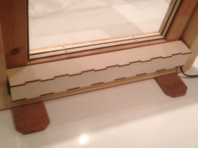
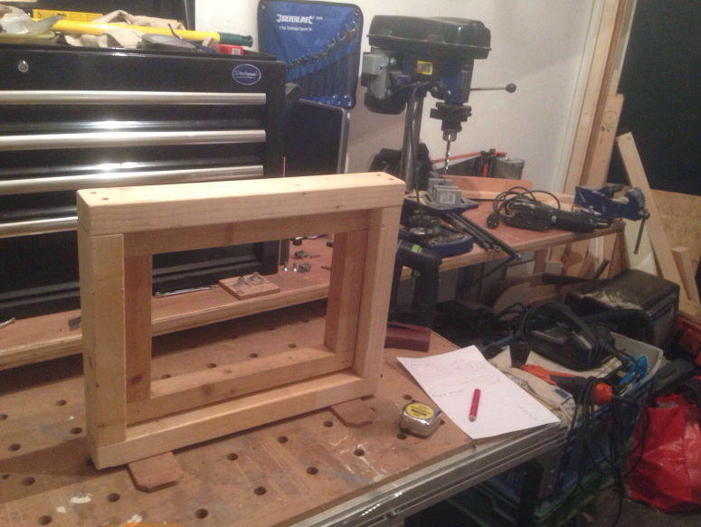
Window frame model for testing mechanics
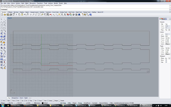
My dad helped me to quickly make a window frame model using his tools and workshop. This model has the same dimensions as the windows in my living room have so I can test the motor and mechanical parts with it. I will also use it for my final project presentation.
Output device: Testing with a stepper motor
To play around a little, I tried if the stepper motor could move the window, but with these (poor) mechanics the motor did not have enough torque.
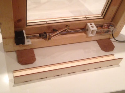
Stepper motor with leadscrew and leadscrew nut
I took a another stepper motor home from the Fablab to test with. The Nema17 Hybrid Stepper Motor (42mm x 42mm) with a leadscrew permanently attached to the axle. On the screw is a leadscrew nut which moves along the screw in a linear direction when the motor axle and screw rotate. I tested it with arduino code and my motor board.
I played around with the speed and the amount of steps to get to know this motor type a little. Also tried different voltage starting from low, going up. This motor is functioning well with 12V. It works with lower voltages such as 7,5V and 9V, but then it is making a permanent noise so it's probably best to keep it at 12V. It was clear that the power of the motor was used more effectively this way, utilizing the screw. The linear movement felt like it was strong enough to open the window and my fellow student Paul Groneveld had useful input for the mechanics which I will test later on.
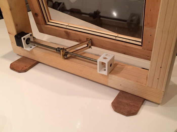
Testing mechanism and leadscrew stepper motor
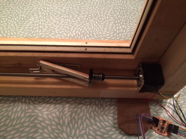
In this test setup I used a metal strip screwed onto the window and a piece of wood and some metal wire to attach it to the leadscrew nut. This piece will be attached with a hinge to the leadscrew nut on one side and on the the other side it will be attached with a hinge to the window.
At first I placed a piece of wood between the screw and the window, but because it then was exactly parallel to the screw it would not make the outbound tilting movement.
Another thing I had to tackle was to keep the leadscrew nut from rotating.
Then the idea of a slot in the piece came to me. This would make it possible for the piece of wood to cross the screw and already be in a tilted position when the motor is at the initial closed window position.
Below you can see that the motor can easily open the window this way.
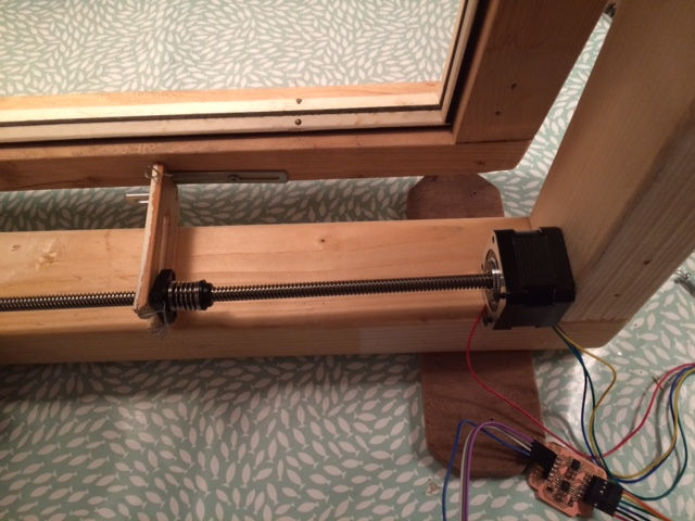
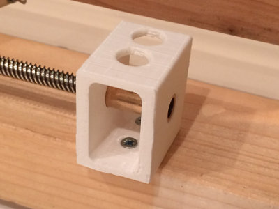
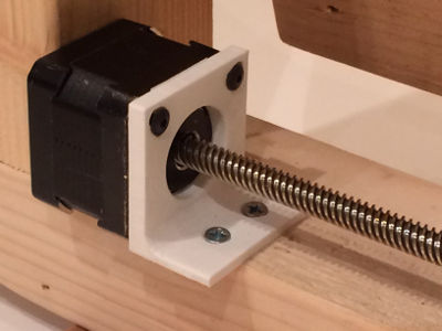
Mounting the motor and the screw
To keep the motor and the bearing for the screw in place I modelled two parts below in Rhino.
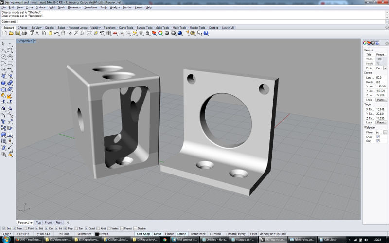 bearing mount and motor mount source files - Rhino
Jannes helped me print them from white pla using the PrinterBot. The two parts came out nicely and I had to use only a little force to insert the bearing in the bearing mount, so it fitted nice and tight.
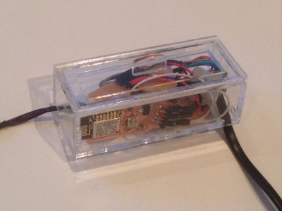
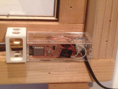
Casing for electronics
To keep the electronics together and protected from dust and moisture I made a little box in Rhino. This box will be next to the motor and will fit under the cover.
 electronics casing source file - Rhino
I cut 3mm acryllic (pmma) on the lasercutter and used Acrifix to join the pieces.
Cover
To cover the whole window system (motor, screw, electronics, wires), I made a cover of 4mm poplar plywood which slides over the motor- and bearing mount. It press fits so I did not need to use any screws which keeps removing the cover very easy.
 cover source file - Rhino
Input device: a CO2 sensor
As a test I connected my MG811 CO2 sensor to analogue pin 0 of the FabKit (ATmega328p microcontroller) I could use from Shirley and I was able to read the output of the sensor using the serial monitor of Arduino IDE.
I found out that the mg811 co2 sensor board is quite sensitive to slightly lower or higher voltages than 5V. It gives inconsistent readings when connected to my transformer which, although set to supply 5V, measured with a multimeter it supplies 5,2V. The sensor does work well when connected to my laptops usb ports.
The parts list/bom consists of:
- 1x ATMega328
- 1x 1UF capacitor
- 1x 10k Ω resistors
- 1x 0.5k Ω resistors
- 1x smd 1012 led
- 1x touch switch
- 1x 6 pin FTDI header
- MG811 CO2 sensor
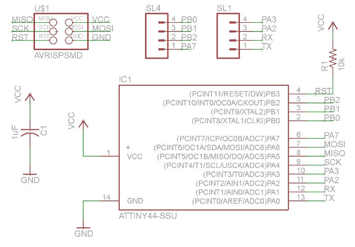
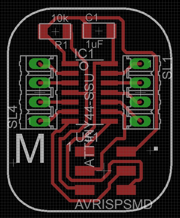
Microcontroller board to control the motor
I had used an Arduino board to control the motor and test with, but now it was time to create a board for this myself. I could have used an Arduino board because I had created more than enough boards to fit the Final Project requirements, but I enjoy making boards myself and an Arduino board would be too big to fit in my casing anyway.
The board would at least need 4 pins to control the motor and a RX pin to receive communication from the esp8266 #2. An attiny44 seemed to have enough pins and memory for this.
The parts list/bom consists of:
- Attiny44
- 1x 10k Ω resistors
- 1x 1uF capacitor
- 1x 2x3 ISP header
- 1x 6 pin FTDI header
- 2x 1x4 row male header
Motor driver board
A stepper motor needs motor drivers to operate. From wikipedia: A motor driver (or amplifier) converts the command signals into the power necessary to energize the motor windings. I wanted a separate board for this function. This motor driver board will be in between a microcontroller board (which will send the command signals) and the motor. It seems to keep things less complicated and more flexible. Also for troubleshooting or replacing defective parts of the system, separate boards seem to be the way to go.
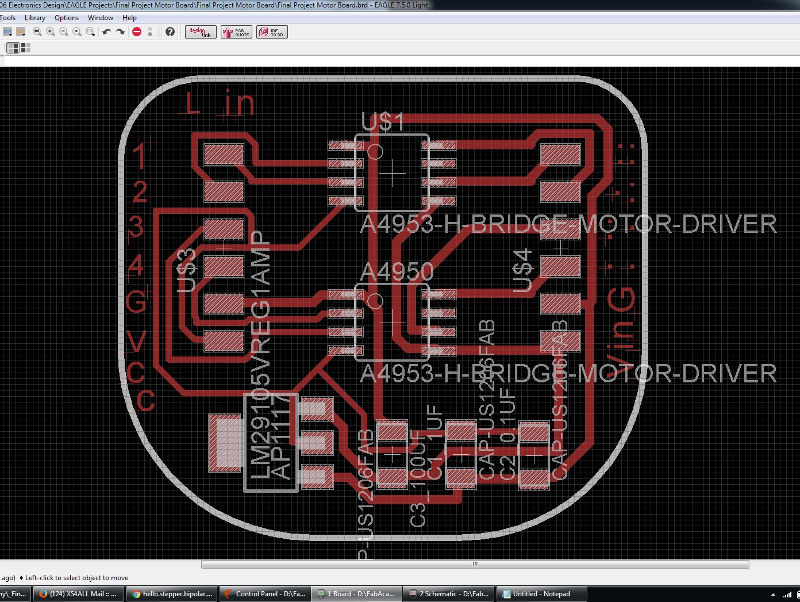
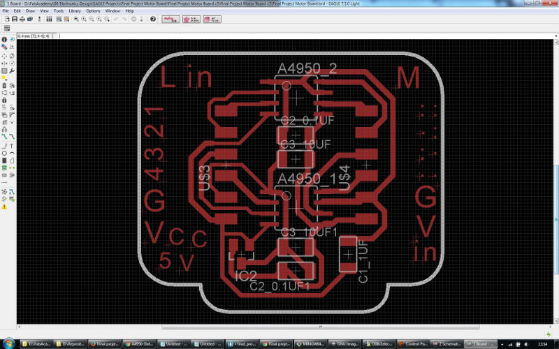
I based my design partly on Neil's example board and I also gathered information from previous years' Fabacademy students. I created a board in Eagle containing the following components:
2x A4950 Full-Bridge DMOS PWM Motor Driver
LM2910 Voltage regulator 5V 1A
100uF capacitor
1uF capacitor
0.1uF capacitor
2x 6pin header
This board will use an external power supply of 12V because the motor I will use needs 12V. The voltage regulator supplies the two motor drivers with 5V and it will be able to supply the microcontroller board with 5V as well. The capacitors are necessary to reduce noise induced by the circuits into the power supply voltages. Used this way they are called decoupling capacitors.
Design issues
When I checked with Emma to see if my design would work she noticed quite some things that were not correct!
She saw the 100uF capacitor and told me that 10uF should be enough for this board and application. As on the example board of Neil, she advised me to keep the 0.1uF capacitor, but to move both that one and the 10uF one as close to the motor driver components as I could. I also needed to add one more 0.1uF capacitor and one more 10uF capacitor so I could place a couple to each of the two motor drivers. Also should place them close to VBB (ext supply voltage), between VBB and Ground. This way their functioning would be more effective and stable.
Unlike on the example board, she advised me to connect the LSS pin of each motor driver to Ground. In the datasheet it says this pin is for "Power return – sense resistor connection" which I am not using so to not let this pin floating I will connect it to Ground.
Another thing I needed was a 1uF capacitor for helping the voltage regulator to function stable.
As a last tip she told me to connect the wide pin of the voltage regulator to Ground. I did not connect it to anything, because I already connected the other Ground pin to Ground, but connecting this fourth pin would help coping with dissipated heat flow.
So here is the corrected bom:
2x A4950 Full-Bridge DMOS PWM Motor Driver
1x LM2910 5V/1A Voltage regulator
2x 10uF capacitor
2x 0.1uF capacitor
1x 1uF capacitor
2x 6 pin header
and an image and the .png and Eagle files of the improved version: motor board v2:
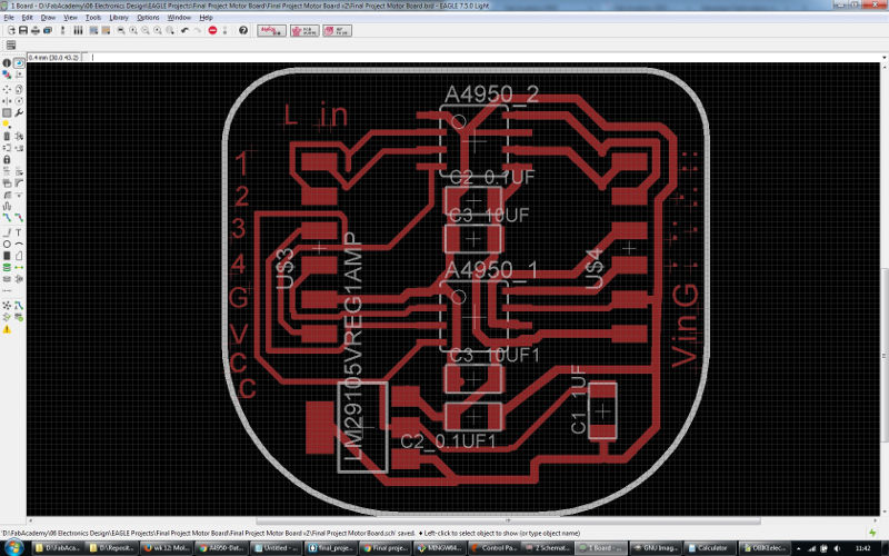 final project motor board v2 source files - Eagle
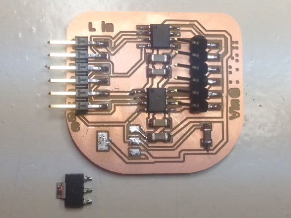
Another issue, wrong component!
After I milled the board I checked it with a multimeter and the traces were good. Then I stuffed the board and it looked fine, but when I checked the connections of the components I found out that the voltage regulator from the Fablab inventory, which I had soldered on the board (LM2940) was different from the one in my schematic (LM2910). The footprint was the same so I could have soldered it on fine, but the pinout is different so the connections were incorrect. I decided to remove the regulator and think about a solution.
Trying to fix it
I created a pad for it by cutting the copper with a knife, next to its original location. This way I could move the regulator to create some space for jumper wires. Then I made tiny jumper wires and the connections of the voltage regulator were now correct.
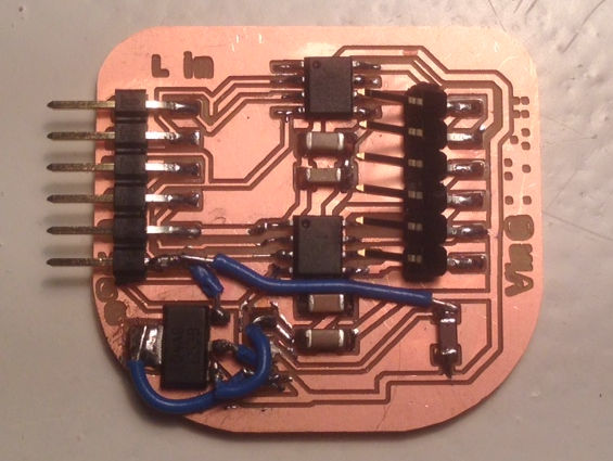
But when I checked the 6 pin header I noticed that one of its pins was connected to a trace and this should not be connected at all! I couldn't see why this was the case and gave up. After spending all that time making the board and adding the jumper wires, it did not feel right to spend anymore time on it. It was around 17:00 so time to go home, but I couldn't take it; having made no progress at all. I checked if someone could take care of my kids this evening and stayed in the Fablab until 22:00 redesigning, milling and stuffing the third and hopefully final version of this board; v3.
 final project motor board v3 source files - Eagle
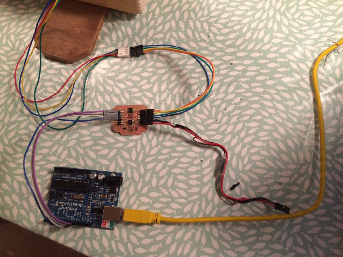
Testing my motor board
I connected the IN1 and IN2 pins of both of the A4950 motor drivers on my motor board to digital pins 8,9,10 and 11 on the Arduino Duemilanove board. Also connected the DMOS full bridge outputs OUT1 and OUT2 of the two A4950's to the 4 wires on the motor (red, blue - green, black: two for each coil). I then used an Arduino example sketch to do a first test to see if the motor board is functioning.
When I searched online I saw different voltages to be used with this motor type so I tested it with different voltages myself. I noticed that the motor only functioned well when I supplied 7,5V or 9V. With 6V it did not rotate at all and with 12V the motor was rotating frantically.
Anyway; it was indeed working and I was happy to see the motor moving!
I played around with the code to see how it would affect the rotation speed and revelutions (amount of steps) of the motor and I attached a laundry pin to visualize the rotation and also to feel the torque of the motor. It felt quite strong at speeds between 25 and 150. I guess that this motor will be strong enough to open the window, but I will see about that when I have built the model of the window frame and window tomorrow and the mechanics after that so I can test this.
And another issue with the motor board..
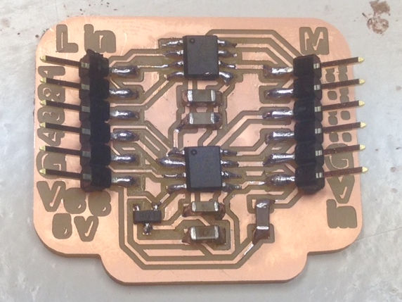
Right when I was setting up things for testing the mechanics I slid the motor connector onto my motor board pin header. I must have pushed too hard and the connector pushed the pin header upwards and the copper pads of the pin header came off... So I had to make a new motor board again!
I did and added glue underneath and against the pin header this time to make it a bit stronger, and ofcourse I will be more careful with sliding on connectors like that one.
Wires overheating!
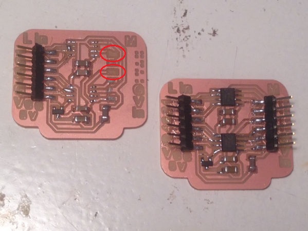
While testing my motor driver board, suddenly I noticed smoke and immediately unplugged the transformer which was supplying 12V to the motor board. The black and the red wire connected to the Vin and Gnd pins of my motor board had become so hot that the insulation had started to melt! I'm not sure why this happened and will check this back in Fablab Amsterdam.
At the lab I checked and found out there was a short on the motor board between VBB and Ground. The current must have been too high for the black and red wires connecting to the VBB and GND pins of the motor board, and they overheated. We could see clearly that the wires to which these two wires were connected didn't suffer from any overheating at all. The short circuit probably damaged the two motor drivers on the board causing the permanent short between VBB and GND. I replaced the two motor drivers and am not using the thinner wire anymore for these type of higher current connections.
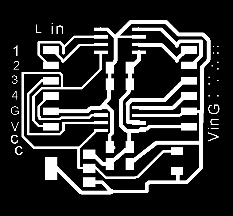
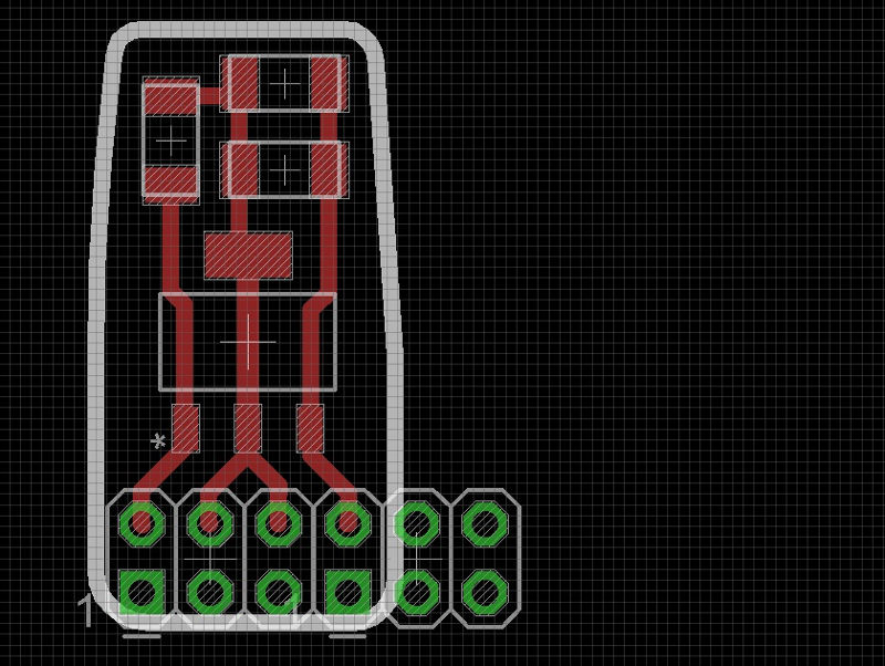
Voltage regulator boards
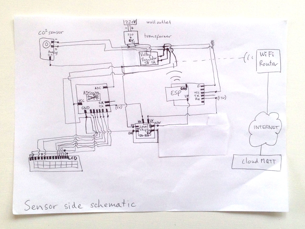
Sensor side
The CO2 sensor board which needs to be supplied with 5V doesn't work on my transformer when it's set to supply 5V. I measured the output and it was 5.2v, so apparently this is outside the operating range of the sensor board. I still wanted to use this transformer I already had so I needed a Voltage Regulator board here.
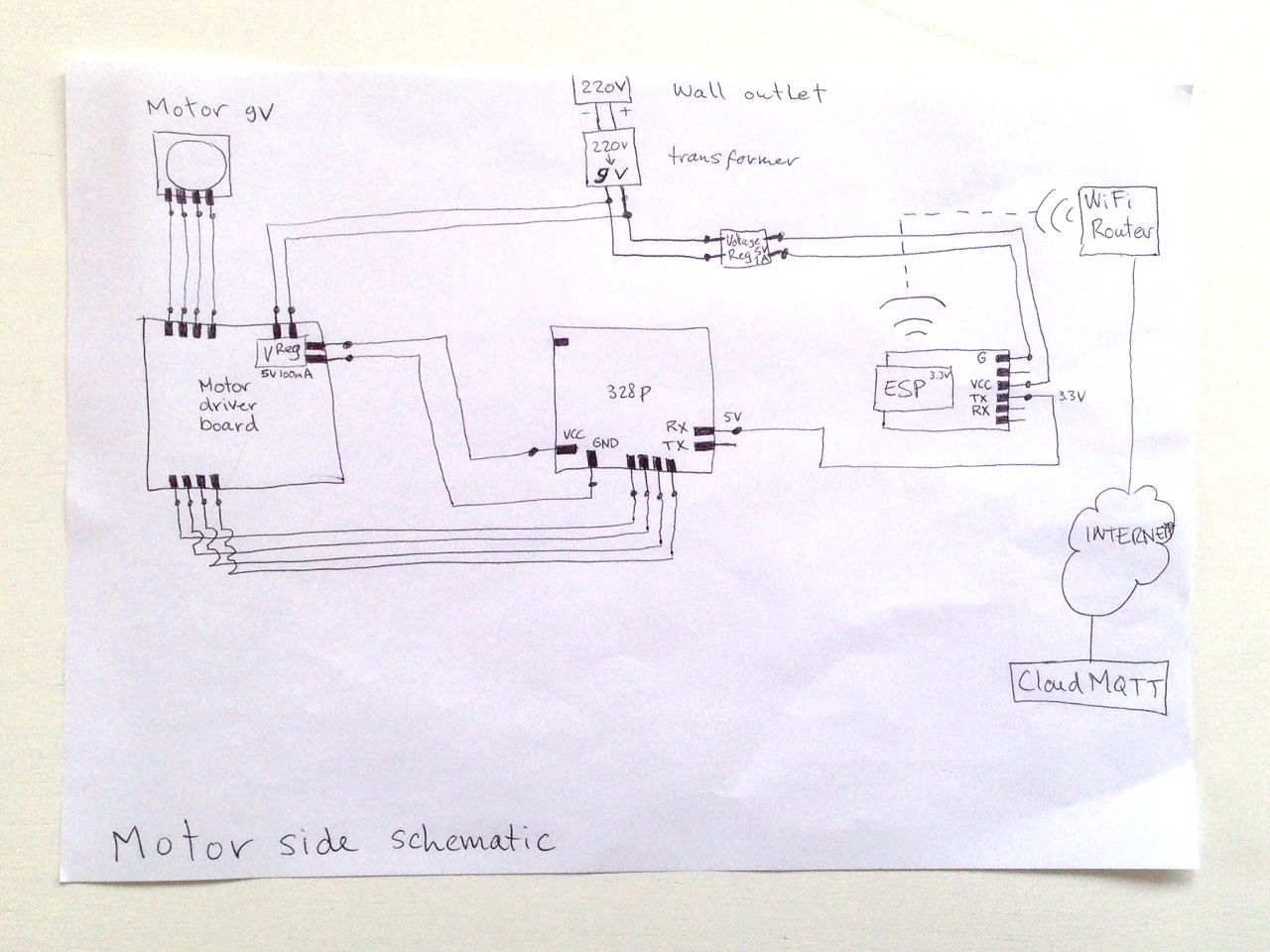
Motor side
I needed another Voltage Regulator board for supplying the ESP8266 WiFi board on the motor side with 5V and at least 300mA because the 5V power source I have availabe on this side is a 5V 100mA Voltage Regulator (which is located on the motor driver board). So I designed and made this little board, but redid it two times to come to the below design. The first design didn't have the necessary capacitors because I forgot to check the datasheet of the LM2940IMP-5.0/NOPB LDO Voltage Regulator (5V/1A) I had used. Emma reminded me and indeed it says:"The capacitor on the Vout side must be at least 22μF to maintain stability" and "a capacitor of 0.47μF on the Vin side is required if the regulator is located far from the power supply filter". Our Fablab inventory didn't have these exact capacitors available so I used 2x 10μF caps in parallel on the Vout side and a 1μF on the Vin side.
On the third and final version I also added a second ground pin, because I needed to have a ground pin for the supply and one for the output as well.
Notice that in the schematic and the board layout I used a 2x03 pin header although it is not what I used on the board. I removed bits of it from the .png file using Gimp to have only the four through hole pads and holes I needed.
I know Eagle has the Via function to add this kind of pad and hole, but I didn't know at what distance they should be for using the through hole pins we have in the inventory so to save time finding that out I did it this way.
Voltage regulator board v3 source files - Eagle
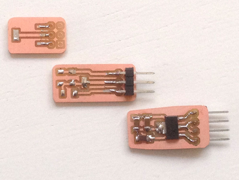 voltage regulator 5V 1A boards v1 v2 and v3
The parts list/bom consists of:
- 1x LM2940IMP-5.0/NOPB LDO Voltage Regulator (5V/1A)
- 1x 1uF capacitor
- 2x 10uF capacitor
- 2x6 header
Schematics
When I was trying to work out all electronic functions and connections I noticed myself drawing things on several sticky notes. After having drawn one for the power plan and a few others I realized it would be more helpful to draw a schematic for the complete electronic situation. It helped me to get an overview and make it easier to discuss my plans with Emma, our local instructor.
Networking
After I had completed the networking assignment in week 15, I created two new esp8266-12e wifi boards to be used for my final project. Read below how I continued from that weeks' progress.
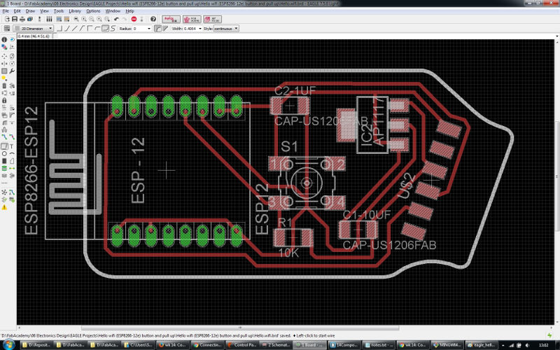
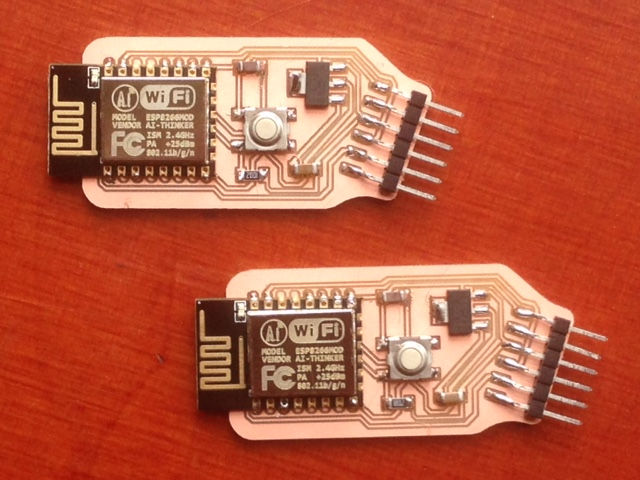
Making two improved wifi boards
Because handling the jumper wires manually to connect them and program the boards is not a very stable and practical way of working I redesigned the hello.wifi.ftdi boards. I added a pull up resistor (read further down the page what I did wrong here..) and a button going to ground to the gpio0 pin. This way the board will be in its normal operating mode by default and I will able to ground the pin during powerup so it will boot in UART programming mode when I need to flash the esp8266. I also swapped the positions of the tx and rx header pins so the ftdi header pins would align with my ftdi cable pins.
So just connect them and program them right?
Well.. no! Trying to program one of them (while keeping the button pressed) I received the following error in Arduino IDE:
warning: espcomm_sync failed
error: espcomm_open failed
error: espcomm_upload_mem failed
It seems like a connection problem again. I tried the other board, but received the same errors so it seemed a design problem.
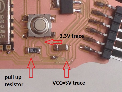
I measured the gpio0 pin and when I pressed the button it was 0V so that worked well, but when I didn't press the button the voltage on the pin was 5V and now it became clear to me why I couldn't program the boards! I had connected the pull up resistor to 5V (which I called VCC in my schematic, but this is actually incorrect as 5V should have been called Vin and 3.3V should have been called VCC). The esp8266 is a 3.3V module so it can not handle more than that on its pins. At this point I also noticed that the onboard led's were not blinking anymore so Emma and me concluded that I must have killed them both..
Fixing the problem
I replaced the esp module on both the boards and cut the trace which connected the pull up resistor to VCC/5V. The resistor trace and the 3.3V trace were running alongside eachother so I connected them with a little piece of wire and soldering tin.
The parts list/bom consists of:
- ESP8266-12E/li>
- 3V3 - 1A - LDO
- 1x 10k Ω resistors
- 1x 10uF capacitor
- 1x 1uF capacitor
- 1x touch switch
- 1x 6 pin FTDI header
Flashing the esp8266 with AT firmware
To test them and to prepare myself for the wifi boards to be connected to the motor board and to the sensor board I wanted them to have a AT firmware again. That way I could use the AT commands if needed. I downloaded this .bin file and flashed the esp8266 with it using the ROM Bootloader utility esptool which is a Python script. Python 2.7.3 was already installed on my laptop and to install esptool I used pip which I already had installed during the Input Devices week (command: python get-pip.py). Below you can see the installation command and response for installing esptool.
D:\FabAcademy\15 Networking\Firmware esp8266\esptool-master> python -m pip install esptool
Collecting esptool
C:\Program Files\Python2.7.3\lib\site-packages\pip\_vendor\requests\packages\urllib3\util\ssl_.py:318:
SNIMissingWarning: An HTTPS request has been made, but the SNI (Subject Name Indication) extension to TLS is not available on this platform. This may cause the server to present an incorrect TLS certificate, which can cause validation failures. You can upgrade to a newer version of Python to solve this. For more information, see https://urllib3.readthedocs.org/en/latest/security.html#snimissingwarning. SNIMissingWarning C:\Program Files\Python2.7.3\lib\site-packages\pip\_vendor\requests\packages\urllib3\util\ssl_.py:122: InsecurePlatformWarning: A true SSLContext object is not available. This prevents urllib3 from configuring SSL appropriately and may cause certain SSL connections to fail. You can upgrade to a newer version of Python to solve this. For more information, see https://urllib3.readthedocs.org/en/latest/security.html#insecureplatformwarning.
InsecurePlatformWarning
Downloading esptool-1.0.1-py2-none-any.whl
Requirement already satisfied (use --upgrade to upgrade): pyserial in c:\program files\python2.7.3\lib\site-packages (from esptool)
Installing collected packages: esptool
Successfully installed esptool-1.0.1
And here the installation command and response for using esptool to flash the esp8266-12e with this firmware:
D:\FabAcademy\15 Networking\Firmware esp8266\esptool-master> python esptool.py -p COM8 write_flash 0x000000 "v1.3.0.2 AT Firmware.bin"
Connecting...
Running Cesanta flasher stub...
Flash params set to 0x0000
Writing 1044480 @ 0x0... 1044480 (100 %)
Wrote 1044480 bytes at 0x0 in 90.5 seconds (92.3 kbit/s)...
Leaving...
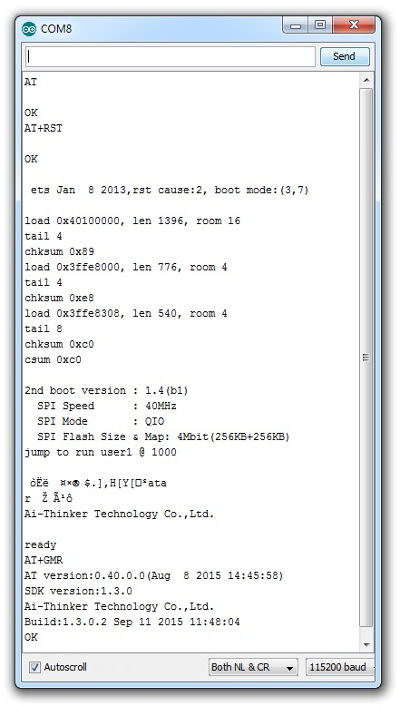
Testing with some AT commands
In Arduino IDE's serial monitor I checked a few AT commands to see if it would respond like I expected. Here is a nice overview and explanation of the possible AT commands for the esp8266.
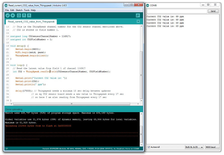
Reading my CO2 sensor data from ThingSpeak (internet server)
After I managed to send the CO2 sensor data to the internet (ThingSpeak) using my esp8266 wifi board during week 15, I now wanted to see if I could also retrieve this same data with the board which could control the motor handling the window. I based my arduino sketch on an example sketch which used the ThingSpeak.h and ESP8266WiFi.h libraries. After I changed things like channel number, field number of the Thingspeak channel I had set up before, and ofcourse my WLAN credentials, I managed to read the values coming from the sensor via WiFi and Thingspeak!
Later I decided that I would use a separate microcontroller board for controlling the motor and use my esp8266 wifi board only for communication purposes because the esp8266 tends to become unstable when it needs to control several output pins (I would need 4 to control a stepper motor via a motor driver board) and utilize its WiFi capabilities at the same time.
 sketch to read co2 sensor data from ThingSpeak via wifi source file - Arduino IDE
MQTT
Later I changed from using ThingSpeak to using CloudMQTT because the MQTT protocol is gaining populairity and will probably be used more and more in the near future for all kinds of sensor related projects. Because of that I thought it would be useful to work with this. I also could make use of existing code from the Making Sense project at De Waag incorporating the json and mqtt protocols.
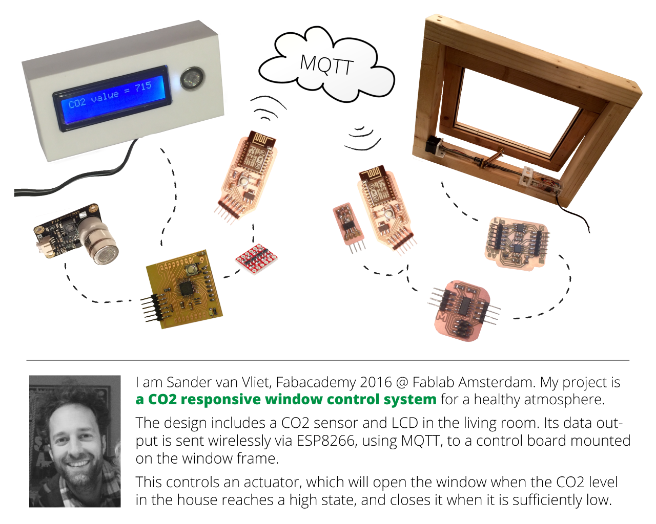
The network is described in the image below.
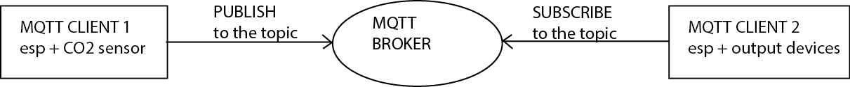
Client 1: it's called clien publisher and it is the esp board that measures the CO2 level. The Data is sent to the host, in this case a MQTT server, cloudmqtt. The software manager of the IoT server is called broker. After a MQTT client is connected to a broker, it can publish messages. MQTT has a topic-based filtering of the messages on the broker so each message must contain a topic, which will be used by the server manager to forward the message to interested clients. Indeed once the data is storage on the server, any device with the right credential can read it back. Each message typically has a payload which contains the actual data to transmit, in this case JSON.
Client 2: it's called client subscriber and it's the esp board that read the data from the server. A client needs to send a SUBSCRIBE message to the MQTT broker in order to receive relevant messages. A subscribe message is pretty simple, it just contains a unique packet identifier and a list of subscriptions.
Code
I used Arduino IDE to create the code I needed to make it work. I combined parts of existing code and changed it with the help of Emma to work for my situation.
There are 2 boards which will be running code on the sensor side:
The sensor/LCD controller board (atmega328p/fabkit)
this will read the signal coming from the CO2 sensor
The pin which the CO2 sensor is connected to is the A0 pin, which is an ADC pin so I'm utilizing the AnalogRead function to retrieve the value.
it also controls the LCD through the use of 6 pins
I used this adafruit tutorial to complete the code to display the current CO2 value.
and it will send a 0 or a 1 depending on the CO2 value being under a minimum or above a maximum threshold to esp8266 wifi board #1
The boards communicate through serial communication. The TX pin of the fabkit is connected to the RX pin of the esp8266. Not directly, but via a level shifter to reduce the voltage as the fabkit is running on 5V and the esp8266 on 3.3V and it can not handle higher voltages. The Serial.print function is used to send the data through serial communication with a baudrate of 9600 bps.
atmega328p/fabkit code - source file
esp8266-12e wifi board #1 (sensor side)
the arduino code on this board uses the wifi manager library to set up a wifi access point and then hosts a html wifi config page where you can enter the local wifi network password. Then the esp connects to this wifi network as a station and receives the data from the sensor/LCD controller board
The code is interpreting the data which it receives on the RX pin. The Serial.read function is used to read the bytes which are then stored in a char variable until it reads a new line command byte (asci command 10). This way a full line is stored before it is being processed further. Then the characters at specific positions within the char variable (a 0 or a 1) are interpreted with the readStr.substring function and stored in a string variable.
it then sends the data (publishes) to an mqtt server
MQTT is a machine-to-machine lightweight protocol which is created with embedded systems, sensors and mobile applications in mind.
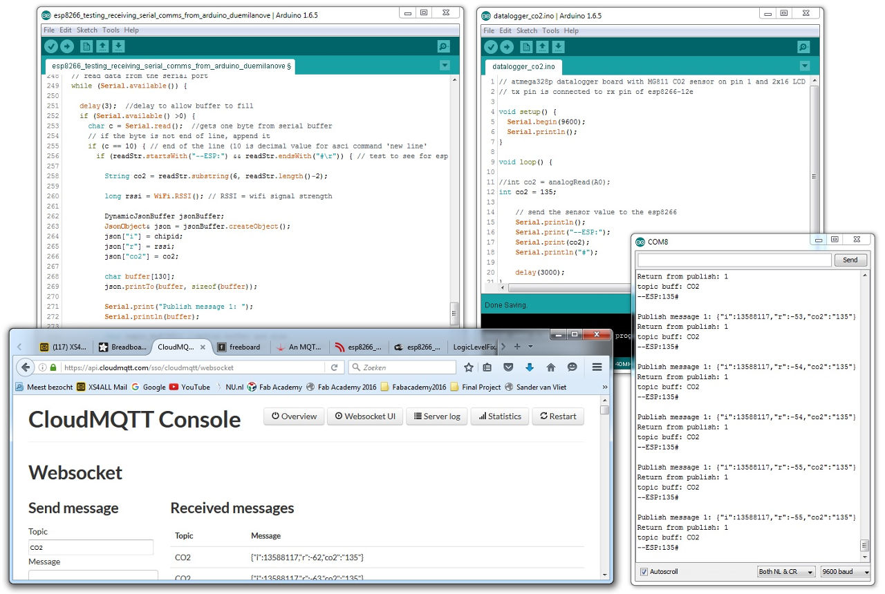
With json.printTo a buffer is defined which includes the data. This is then used with the mqttClient.publish command to send to CloudMQTT, a globally distributed MQTT 'broker' which distributes and saves the data.
esp8266-12e #1 code - source file
Testing the code for the two boards above
Here you can see the esp8266 receiving the data from the Arduino board. In this test case it is no live sensor data, but a fixed value (int co2 = 135). Then the esp8266 publishes this value to the CloudMQTT topic which you can see coming in on the CloudMQTT console. On the serial monitor (COM8) you also see the esp8266 writing what it is receiving from the arduino board and what it is publishing
to the CloudMQTT topic. On the right is the schematic for this test setup.
And there are 2 boards which will be running code on the motor side:
esp8266 wifi board #2 (window side)
this connects to the internet with the WiFi.begin command using the ESP8266WiFi.h library and downloads the data (subscribes) from the above mentioned mqtt server with the command client.subscribe using the PubSubClient.h library.
and it forwards the data to the window controller board through serial communication with a baudrate of 9600 bps.
esp8266-12e #2 code - source file
The window controller board
this will receive the data from the esp8266 wifi board #2 and stores it in a byte variable (this can store an 8-bit unsigned number, from 0 to 255).
and using the Stepper.h library, it will send control signals to a motor driver board (which then drives the motor), opening or closing the window depending on receiving a 1 "if (ch[0] == 48)" or a zero "if (ch[0] == 49)". Characters which are sent via serial communication are interpreted as ASCII characters and encoded with the decimal number corresponding to the character on the ASCII table. In the ASCII table you can see that a 0 is represented by 48 and a 1 is represented by 49.
attiny44 code - source file
Testing the code for the two boards above
Here you can see a test where the esp8266 connected via WiFi and subscribing to the CloudMQTT topic. Then it is sending the value via serial print from its TX pin to the RX pin of the Arduino board. Because I could not use the ftdi cable (TX and RX serial comms source and destination boards need to share the same power circuit) I added feedback to the code by turning the onboard LED on every time the Arduino board received the data from the esp8266. For this test setup I sent the data manually by sending it through the MQTT console which uses a web socket for publishing and subscribing.
Putting it all together
At this point I had completed all the components and I assembled my whole system.
At the top of this page you can see a presentation slide and my actual presentation video which has been recorded during the Final Project presentations on june 15th 2016.
Ideas for improvement
Below is a list of things I could add to the system to improve it in the future:
Switch power: I could add functionality which switches the power to the motor on only during operation. This would save energy consumption and make the system silent for most of the time. This can be done with a relay or using a motor driver with enable/disable or sleep status functionality.
End stop control: For stable functioning in the long run I could add end stop sensors to avoid changes in the range of movement of the motor in case it misses some steps.
App for manual window control: I could use Blynk and create a smartphone app to manually control the window
Visualizing data: I could use Plotly or Freeboard to make a dashboard to vizualize the data which the CO2 sensor generates
The last day of Fabacademy 2016
And then, as if it has come all of a sudden, here it is.. Today was the last day of the Fabacademy digital fabrication course (originated from the MIT course "How to make almost anything") that dominated my life for the last six months.
AMAZING, really amazing! Time flew by and it has been inspiring to me. Hard work throughout almost the whole course because of the rythm of the weekly cycle of subjects and assignments, but I really enjoyed it too.
I didn't write my documentation in diary style, but today I feel a bit like writing memoires. Amazing, what intense days and actually last few weeks I have had finishing my final project. With as a climax todays long and productive last session with still quite some issues that needed debugging.
And it all came together! I surprized myself and I am happy with the result which I will be presenting at the final presentations.
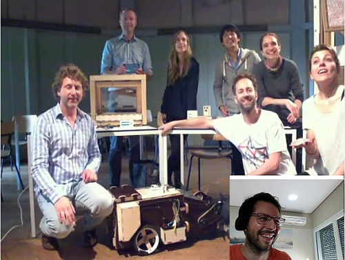
Below is the group of students I was part of for these 6 months and on the right is Emma Pareschi, our local instructor and coordinator. On the little screen is our remote reviewer Luís Carvão.
Credits, props, love and respect =)
I want to thank my girlfriend Shirley for supporting me in deciding to enter Fabacademy and for her input and moral support during the whole course.
A very big thanks to Emma Pareschi, who was always dedicated and very helpful. Also to Luís who had useful input for us during the weekly review sessions.
And to everybody else who helped me in any way they did!
This work is licensed under a Creative Commons Attribution-NonCommercial-ShareAlike 4.0 International License.