Sander van Vliet
Fabacademy2016
@Fablab Amsterdam
Networking and Communications
Week 15 (11 may - 18 may)
Lecture
This weeks class was about networking and communications so we were introduced to various ways of communicating through the means of a network like asynchronous as well as synchronized serial communication. Many other things were discussed like the OSI layer model, internet protocols and modulation. Several types of wireless network standards were explained like radio frequency, bluetooth and WiFi and for a more detailed overview of the lecture you can check the class lecture file.
Assignment
- Design and build a wired or wireless network connecting at least two processors.
What to make
For this weeks assignment, again I wanted to do something that can be useful for my final project.
At the window I will have the motor board operating the window and somewhere else in the room I will have the sensor board containing the CO2 sensor and LCD. These boards need to communicate to each other so the window can be opened and closed by the motor (output device) depending on the value that is read by the CO2 sensor (input device). For this I need to create a network of some kind and because I would like to be able to retrieve the sensor readings on my pc or on an LAN/internet server as well I will use a wifi connection between the two boards.
Making two WiFi boards
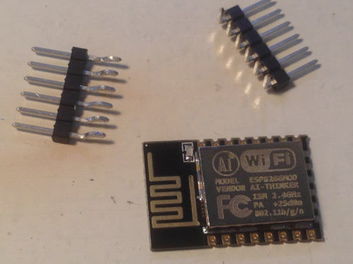
I recreated two of the hello.ESP8266-12E.ftdi example boards which can be connected to other boards with a serial connection. This board contains a:
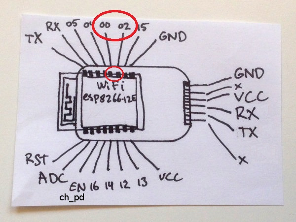
ESP8266-12E WiFi serial transceiver module like this:
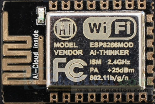 In short, the ESP8266 module is a TTL "Serial to Wireless Internet" device which includes GPIO (in- and output pins) with hardware-based functions like PWM, I2C and ADC.
A 6 pin FTDI header for programming it
and a 1 Ampère voltage regulator and two capacitors (1 uF and 10uF) to supply the ESP8266 with 3.3Volt
In short, the ESP8266 module is a TTL "Serial to Wireless Internet" device which includes GPIO (in- and output pins) with hardware-based functions like PWM, I2C and ADC.
A 6 pin FTDI header for programming it
and a 1 Ampère voltage regulator and two capacitors (1 uF and 10uF) to supply the ESP8266 with 3.3Volt
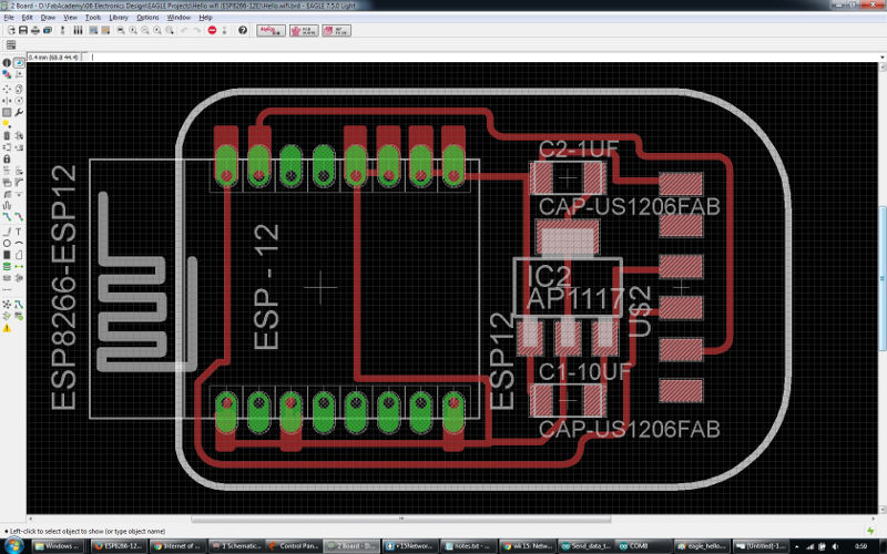
I had created the schematic and board layout files in Eagle the previous evening:
hello.wifi.ftdi source files - Eagle
and right after the networking local lesson I had about 4 hours to mill and stuff the two boards. My schedule came under pressure because I ran in to a few issues while making the boards.
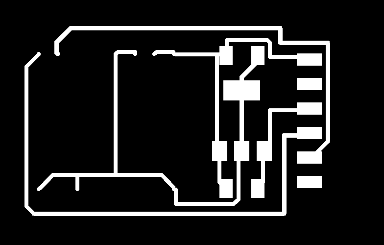
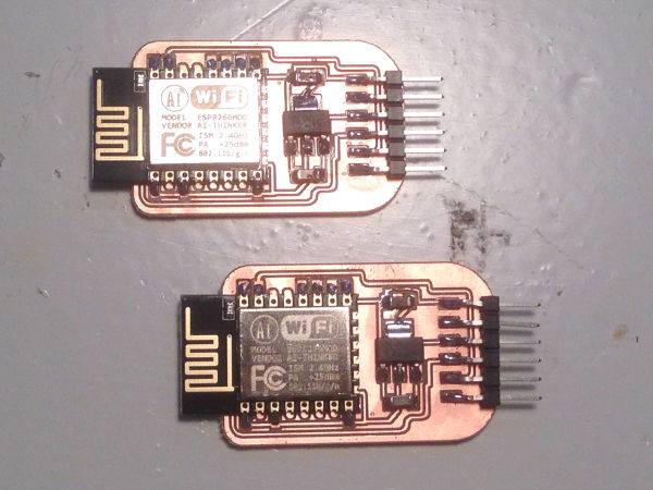
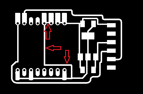
To start with I had forgotten to turn on the pads layer in Eagle when I exported the board layout to .png to create the traces file for the Modela. This resulted in having no copper pads for the ESP8266-12E module, see below:
Without the pads I could not solder the esp module to the board, so I had to make the .png files again and mill two new boards again. Here are the two source files including the pads:
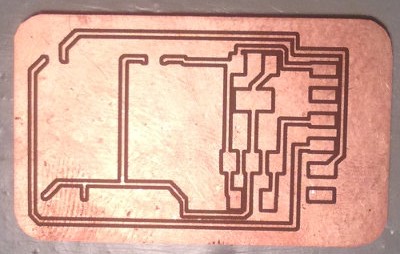
Milling the traces went fine again and so this time with the pads, but after the cutout job with the 1/32mil end mil I noticed that it didn't mill deep enough so the boards were still attached to the plate of FR1 (which is the paper based copper plates we use). I guess I forgot to select the 1/32 milling bit size in Fabmodules and this probably caused it? So I started the job again but now with this setting correctly selected. (I was glad that I had taken a photo of the X and Y origins of the traces job in Fabmodules before!) and this time it did cut out the boards.
While soldering the through hole 6 pin ftdi header of which I had bent the 6 pins to make it into a horizontally lying smd ftdi header (see below)
 I heated up 1 ftdi header pin pad for too long and the copper layer came off. Luckily this was the copper of an unused pad and although it's good to solder it for stability of the 6 pin header it was not an issue that I could not solder this specific pin.
I had to hurry so I quickly tested the connections with a multimeter and everything looked fine so then I rushed to get on the train home.
Programming the boards
That evening at home I tried programming the boards using Arduino IDE and sending AT commands through the serial monitor. In Arduino IDE's Boards Manager I added a board named Generic ESP8266 Module by adding http://arduino.esp8266.com/stable/package_esp8266com_index.json to "Additional Boards Manager's URL's" under Edit - Preferences. I connected the hello.esp8266-12e.ftdi board to my laptop with the ftdi cable and although it all looked to be fine and I thought my boards were be ok, I did not succeed to program the boards. I kept receiving the following error messages right after compiling:
warning: espcomm_sync failed
error: espcomm_open failed
error: espcomm_upload_mem failed
It seems like a connection problem and I searched and read several possible fixes but found none that worked.
I also couldn't get all the expected responses to the AT commands in serial monitor.
With the command "AT" I receive "OK" and with the command "AT+GMR" I receive a response containing the current firmware version, but to the other AT commands that I tried I receive the response "ERROR".
Testing with the NodeMCU devkit
Our local instructor Emma was so helpful to give me a NodeMCU devkit from the Fablab to be able to try some things out at home in case my self made boards would give issues.
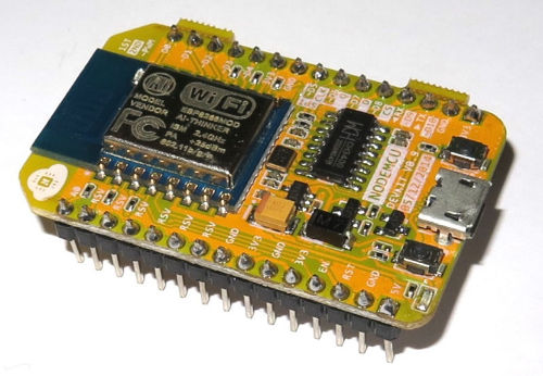 The NodeMCU is a board which includes the ESP8266-12e WiFi serial transceiver module, an LED, a voltage regulator and a CH340G USB/UART converter chip / USB to Serial adapter for communication with a pc directly (find MAC, Linux and Windows drivers here).
I installed the driver and could see in Windows Device Manager that it was installed correctly and was using Port 7.

I found this site which was very helpful and I managed to program the board using Arduino IDE after I selected the correct board in board manager. I used a sketch I found here and got the NodeMCU connect to my WLAN.
Continuing with programming my boards
Only later I found out why my boards were not responding the way I expected them to.
At first I thought that grounding the gpio0 pin was necessary only when flashing a new firmware on the chip (which I don't need), but after spending much time searching good information about the esp8266-12e I found out that the gpio0 pin has to be connected to ground at the moment it is powered on to enter UART programming mode while booting. When booted this way it can be programmed via UART/serial/tx-rx.
On http://www.forward.com.au
I found information about boot settings that can be controlled with the GPIO0, GPIO2 and GPIO15 pins on the ESP8266, see below:
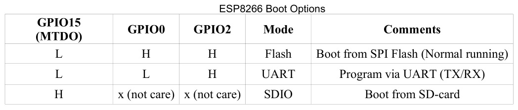 "For normal program execution GPIO0 and GPIO2 need to be pulled up to Vcc (3.3V) and GPIO15 needs to be pulled to GND, each with a resistor in the range 2K to 10K resistor. A 2K resistor gives better noise immunity. OLIMEX uses 2K resistors SparkFun uses 10K resistors. I use 3K3 resistors.
The settings of these inputs is only checked during the power up (or reset) of the chip. After that the pins are available for general use, but as discussed below their use is restricted by these external pull up/down resistors."
! Please note that the information on that page is meant for using with the ESP8266-01 module, but it partly applies to the ESP8266-12e module that I use.
I desoldered the WiFi module and cut the trace which connected gpio0 to gpio2 and to vcc.
 Then I resoldered the esp module. I also soldered a cable (blue) to a pin which is connected to ground so I could manually connect gpio0 to ground for programming. On the photo you also see a cable (black) connecting the gpio2 pin to VCC again (after I had to remove the trace between that pin and the gpio0 pin).
 Again I tried and tried, but still I couldn't program it! Then something else came to mind: the tx and rx pins of the ftdi header on the hello.wifi.ftdi board should be connected to their opposites on the ftdi cable, so tx to rx and vice versa. BUT these pins on the example board are actually not aligned with the connector of my ftdi cable.. I guess this is Neil's way of making you troubleshoot and learn this way =)
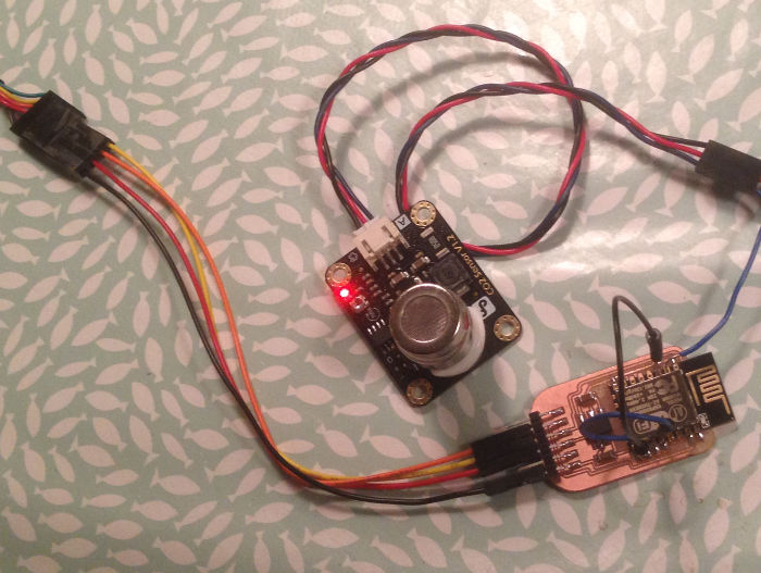
Once I crossed the tx and rx connections with separate wires (orange and yellow) and tried a few times I managed to program the module with a sketch which made it connect to the WLAN in the Fablab!
Sending data to the internet
Now that I was able to connect my altered hello.wifi board to a WLAN I wanted to try sending information out to the internet. I found an example sketch here and I connected my CO2 sensor (powered by an external transformer set to 6V) to the analog pin of the esp8266 module (ADC).
Then I changed the arduino sketch to match this setup and I created an account at ThingSpeak.com where I set up a channel for the data to be sent to and to be visualized and here it is!

The values are not stable, probably because I had only just powered on the sensor and it needs more time to get to its operating temperature to generate proper results, but I am glad that I have proven the concept of networking that I will use for my final project!
Next to a 'Write API' you can also read data from ThingSpeak using a 'Read API'. This could be a way for my sensor and motor boards to communicate.
sketch to send co2 sensor data to ThingSpeak via wifi source file - Arduino IDE
How does Client/Host Comunication work?
The connection between the esp and the platform Thingspeak is based on a Client/Host relation. In this case the esp is the client and thingspeak is the Host. In this contest 'host' means the virtual and physical space that manages the collection and storage the data. The IoT platform uses channels to store data sent from apps or devices. Every channel has its own auto-generate ID, the Client can so identify the right location where to publish.

A great source of information
(which I only ran into around the time I fixed the boards at the end of this interesting networking week)
Next to the internet sources I referred to I would like to add a link to Neil Kolban's site. He wrote -and keeps updating- a great e-book about the esp8266. Very well documented valuable information for anyone using the esp8266 and the development kits built with it.