The lecture was about many aspects of mechanical design like common design principles, materials and ways of fastening, framing and driving. Also bearing types, conveyors and lubricants as well as different types of mechanisms. For examples see the lecture class file.
Assignment
Make a machine, including the end effector. Build the passive parts and operate it manually. Document the group project and your individual contribution.
We were supplied with motors with integrated lead screws, anodized aluminium rods as guide shafts, and nylon bushings. The idea was to either use these reconfigurable stages made out of tri-fold cardboard or create something ourselves to use the motors for our machine.
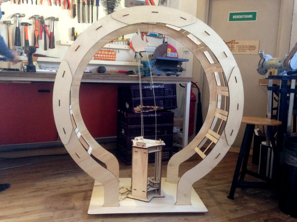
And this is what we made!!
Here is a video which shows the machine up close during the last steps of assembly and programming:
Our local instructors Emma and Mickael guided us through the first step: gathering our ideas and discussing concepts and functionality. In teams of two we made lists of 5 properties we thought to be interesting for our machine. This could be any functional, aestetical, emotional, technical or conceptual property or anything else we would like to see in our machine. The properties I suggested were: Including a circular motion, writing text, making drawing, stamping something, using water in the process/use floating elements.
After clarifying and discussing all input we voted which properties we wanted to let go and we ended up keeping the following: should make us laugh, anyone can use it, having an organic motion/flexible part, including an interface.
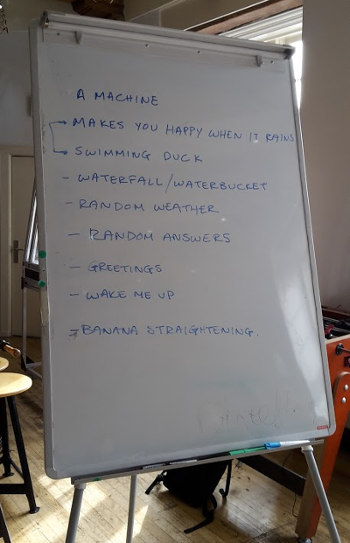
Then we thought of functions the machine could have and we came to this list:
After voting it became clear we would be making a Random answer machine!
How it will give a user answers exactly, we still have to figure out, but now we have something to work with.
A first test
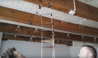
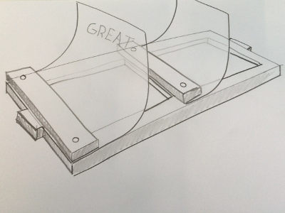
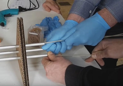
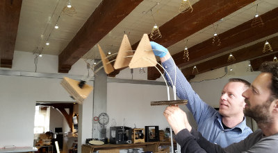
After combining the chosen properties and function we came to the idea of using glassfibre rods which will be moved up and down by the supplied lead screw motors. The rods will form an arm which maybe can push up or out some form of answer cards.
A fellow student lasercut some parts which is keeping the rods at a certain distance in a triangular shape and we put together this first model to be able to test the concept:
After having tested we concluded that the arm was unstable which resulted in torque and we were not able to control the arm well enough.
A second test
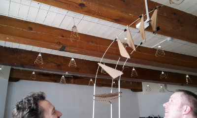
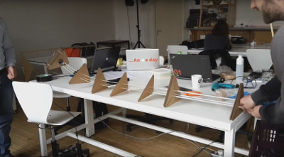
We changed the model to a wider configuration and tested again. This time it was more stable and now we could control it a lot better. Having the arm upright was the position in which we wanted to use the arm in the machine.
The concept was proven to be working well enough to continue developing the machine with this type of arm using glass fibre rods.
With Jacopo I also did tests with an arm constructed of 4 glass fibre rods, but this configuration did not seem to be as flexible as the three rod version. The fourth rod limited the moveability of the arm.
Assembling the frame
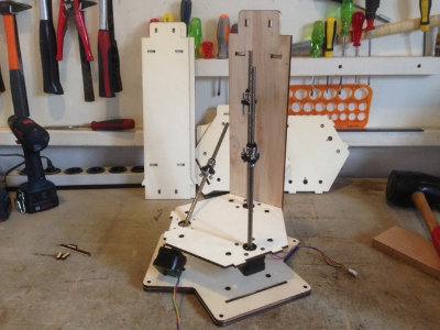
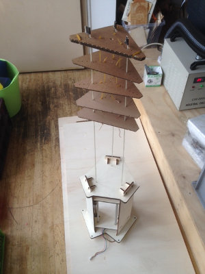
After Paul had drawn parts I bought a sheet of 6mm poplar plywood. I did some tests and gave feedback to Paul about the kerf so he could adjust the drawing so the press-fit slots would fit nicely (the sheet thickness was actually 5,7mm, while being sold as 6mm..) I then used the laser cutter to cut the parts and assembled the frame, inclusing the motors and aluminium rods. It seemed fine and it was nice to see how Paul had constructed it.
After assembling the frame I added the three glass fibre rod arm and already we could see the machine taking form!
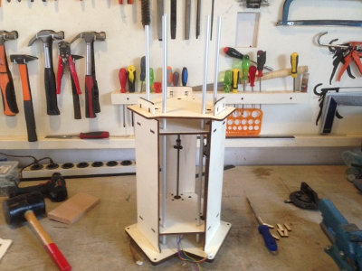
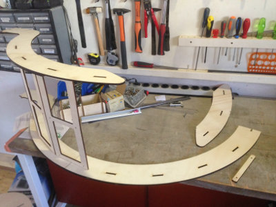
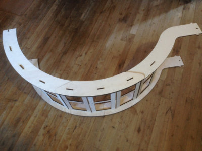
Assembling the arch
Now it was time to assemble the arch which will be placed over the machine. On the arch there will be answer cards which can be pushed out by the arm to show them to the user.
I was not present when these parts were discussed and designed so it was a bit like a puzzle, but I had a general idea how it should come together.
I knew there was one part missing as my fellow student Shunichi could not finish all parts during the previous session. I cut the missing part on the laser cutter and started putting the parts together.
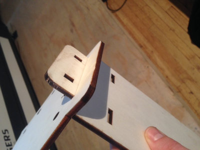
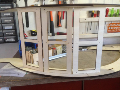
I missed the fact that the card holders are not symmetrical and thus directional. On the right photo you can see that one of the three card holders is not in the same direction as the other two (see where the four holes are).
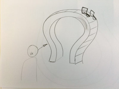
After talking to Sebastiaan on the phone it still was not fully clear to me how the cards would be moving and which way they would be facing the user of the machine. Sebastiaan said he would clarify by sketching it and after I had seen the below sketched he sent me, it all became clear!
It's quite an experience to work on a project as a team when you are not working at the same location all the time. When the team has just recently been formed it also becomes clear that every person has their own way of communicating, like Sebastiaan is a more visually inclined person than me. He prefered explaining by making a sketch, where I would probably have chosen to explain using words (audibly inclined).
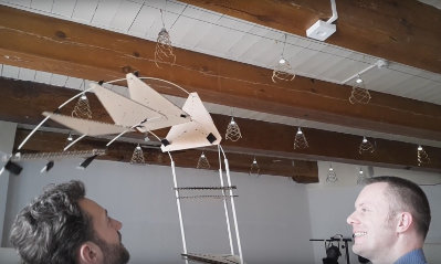
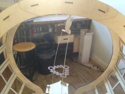
I put both the arch parts together, connected them and placed the full arch over the machine.
I noticed that the hand was not aligned with the arch and after consulting Sebastiaan again I took it off and put it back on the arm end plate the way it was designed to be aligned.
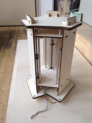
Very nice to finally see the shape and dimensions of our machine!
Creating answer cards
We would use transparent sheets for the answer cards and now we needed some answers! =)
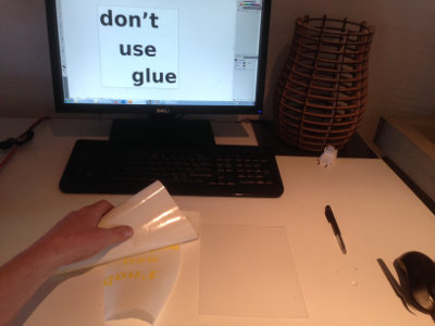
I made up and had gathered all kinds of random answers and asked the others in my group to review these and add answers they would like to use for our machine. I started with an answer that actually became a running gag during the Computer Controlled Machining week. Having to design press fit products for that weeks' assignment, we were told that using glue would be a sign of failure and ever since, many times this was used as a joke in our group.
I used Inkscape to create the text and cut the vinyl stickers on the Roland GX-24 (speed 20cm/s and force 80gf) from Illustrator. I applied the stickers on the transparent sheets using application film.
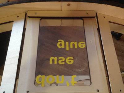
Below you see how the transparent answer card is pushed out (with my own hand for now), showing the answer to the user of the machine.
Opportunities for improvements in the design
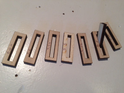
Press-fit slots too tight
During the assembling of the frame I had a bit of an issue because the press-fit slots did not fit as nicely as I thought. I had ran some tests with small parts to see how big the kerf would be, but the real parts did not fit as well because they were a lot bigger than the test parts. Because of this there was much more friction between the slots and the internal parts. I had to sand parts to make them fit better so the design can be optimized by making the slots a little bit wider.
Arch parts not staying in place
The arch consists of multiple parts which are being held together by the press-fit connection between them. I noticed that after a period of moving, working on and using the machine, these press-fit connections became more loose and at one point one of the arch pieces came off. The design can be improved here by extending the answer card 'window' parts a bit and securing the press-fit connection with a slot-and-pin connection as used for securing parts of the base structure.
Position of the machine
The user of the machine should be able to see the answers well as the machine pushes them out of the frames. For this, the top edge of the arch of the machine needs to be around eye-height of the user. The design could be changed so that the base of the machine is higher. This way it can stand on its own and does not need to be placed on a table or some other structure. This will make it more stable and I think it is a nice idea in general.
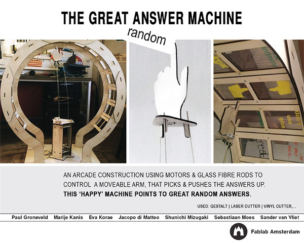
 After voting it became clear we would be making a Random answer machine!