Assignment
group assignment:
- design a machine that includes mechanism+actuation+automation
- build the mechanical parts and operate it manually
- document the group project and your individual contribution
In this assignment we had to work as a group, and based on the resources we have in the lab; the maximum Rod length available is 40cm so our two axis machine will be limited to 40 x 40 cm .
For that we decided to create a machine that has the Y axis on the Rod and the X axis on wheels:
The Y axis is limited to 40cm (maximum Rod Lenght) and the X axis is unlimited and it will be on wheels.
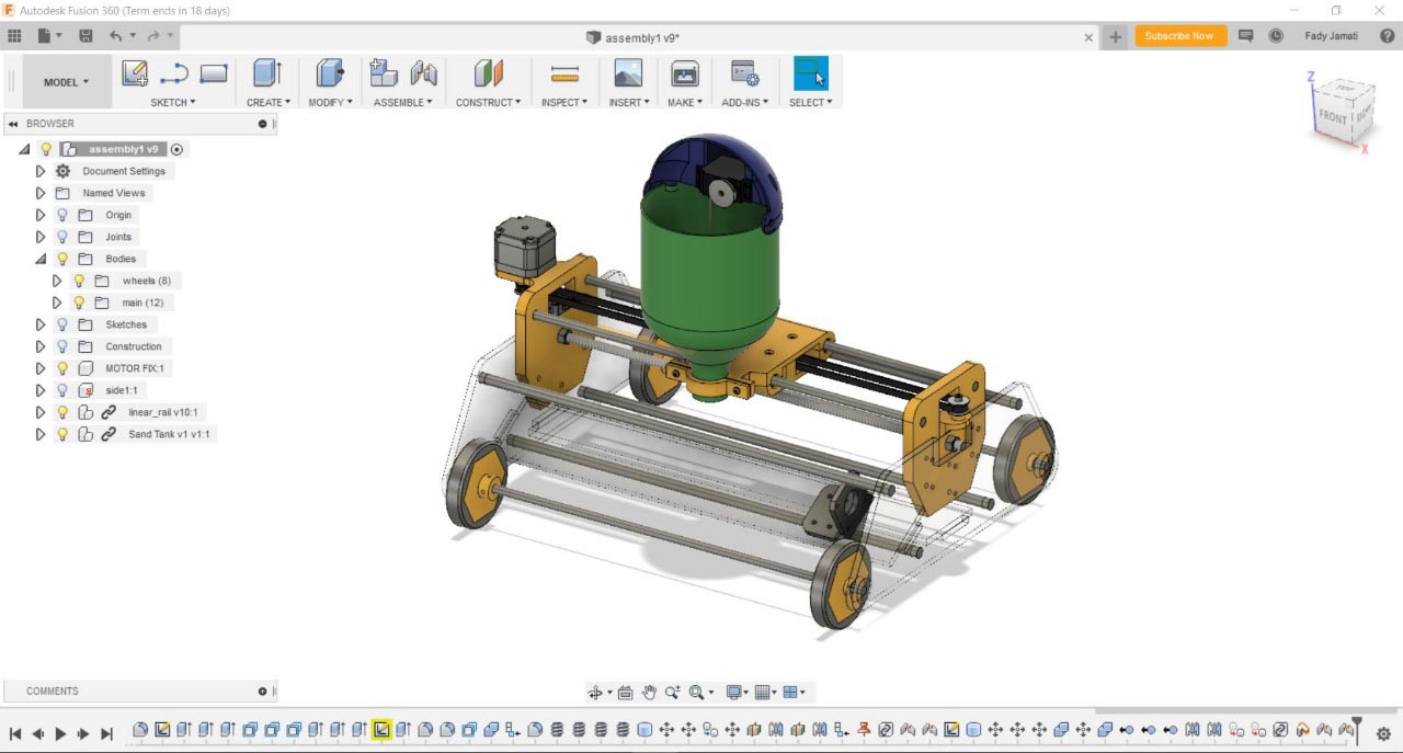
Our machine will be a sand plotter ; it can be placed on the floor and make drawings with sand of 40cm width and unlimited lenght
The project is divide into 4 parts and distributed on the 4 group members:
- The Main Body (the X axis)
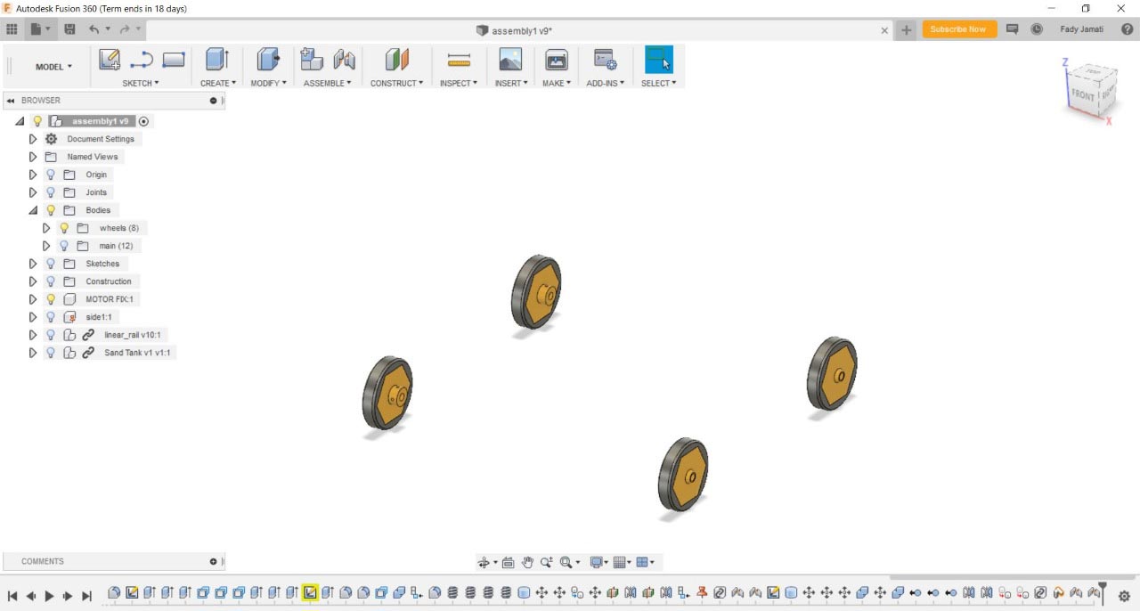
- The Wheels
- The Linear Rail (the Y axis)
- The Sand Holder or the Nozzle

The Main Body.
The Design
For the main body I started sketching on Autocad to visualize the overall dimensions with all the parts
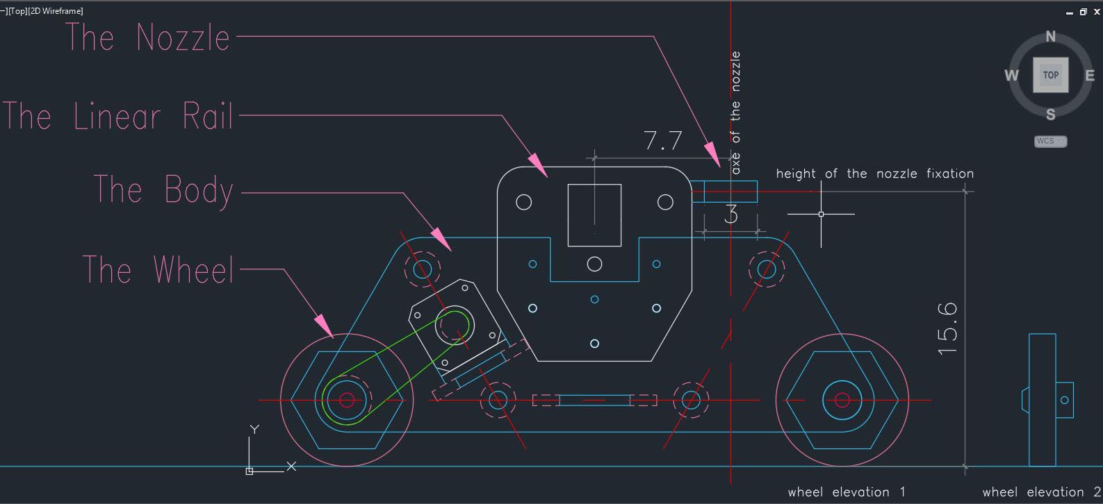
And below is the main body details
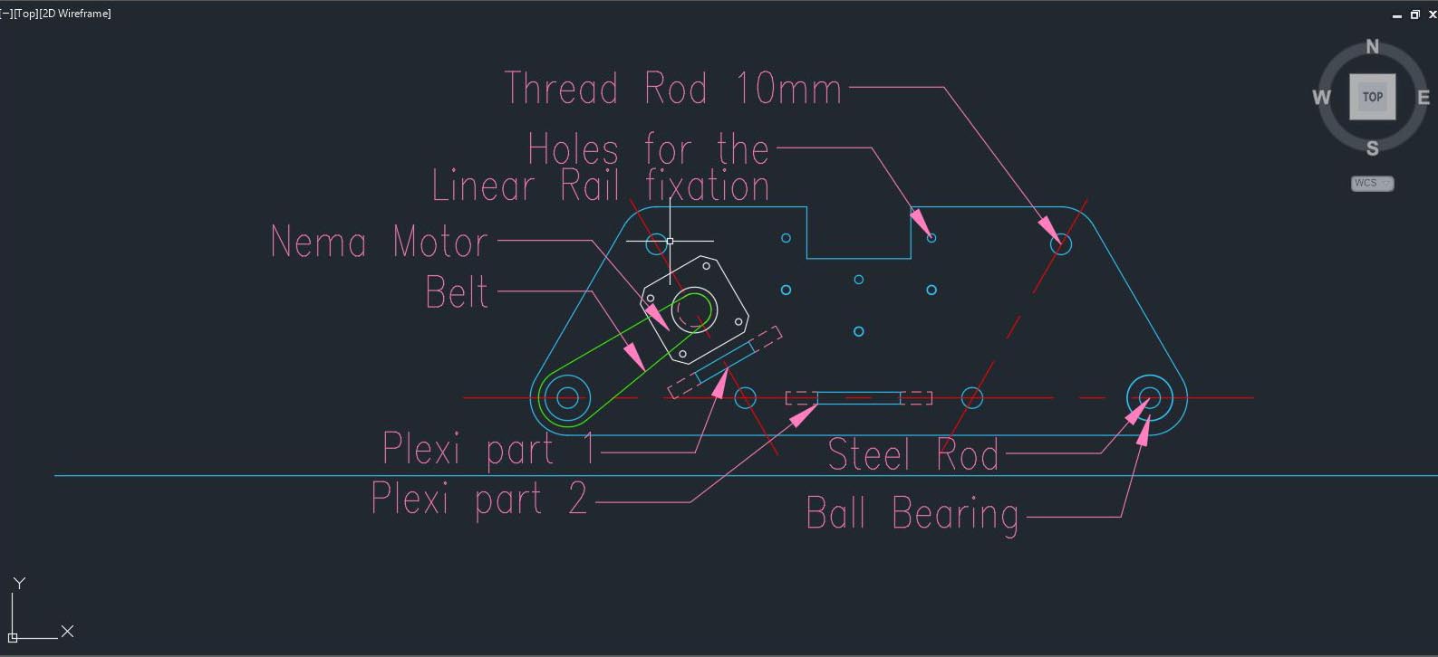
The Idea is to have 2 main plexi part (6mm thicknes) linked together with four 10mm Threaded Rod. Four ball bearing will be inserted in the plexi part to hold two 8mm steel Rod which will hold the wheels.
Two other plexi parts will are placed perpendicularly between the main plexi part to give more rigidity to the body ; Plexi part 1 will hold the Nema motor and the Plexi part2 will be holding the Battery and the Electronic Board.
Three holes are made in the main plexi in order to hold the Linear Rail.
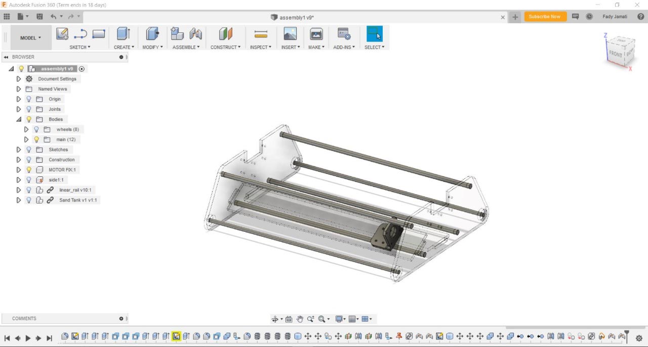
Now I will insert the dxf sketch on fusion to 3D model it and visualize it with the other parts.
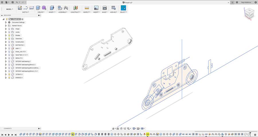
After drawing the 2 main plexi pats , now I will draw the Plexi part 1 and Plexi part 2

Now I will add the 10mm Threaded Rod linking the main parts together.

Than I will add the two 8mm Steel Rod and the four ball bearing holding the wheels.
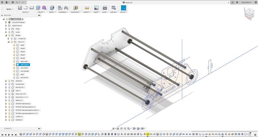
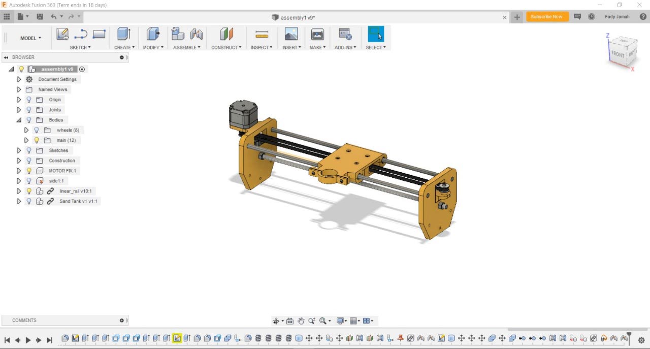
And finally I will add the Nema motor and it's support.

The Production
The ball bearing should be tightly inserted in the plexi part: for that some testing should be made and calculate the kurf.
The ball bearing diameter is 22mm and the best fitting hole turned to be 21.8mm and the kurf is 0.1mm
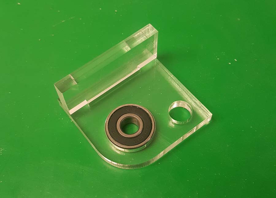
Based on that I will adjust the design, extract the dxf profiles and prepare them for plexi laser cutting.

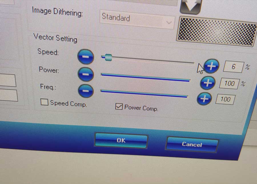
Laser cutting the parts.


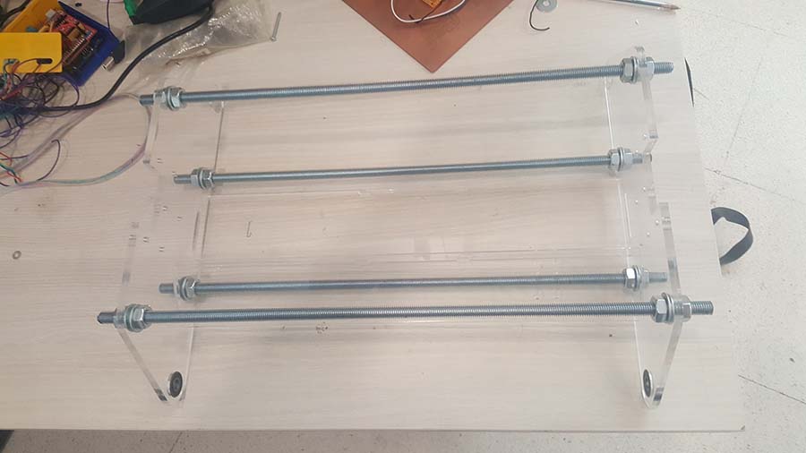
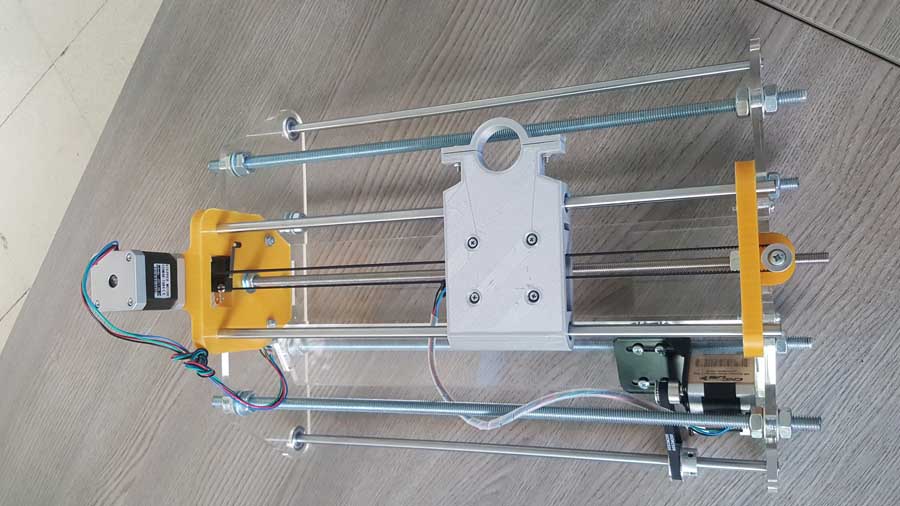
The Assembly
I will start by assembling the plexi parts and the threaded rods.
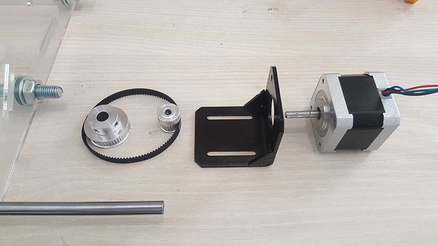
Than I will assemble the motor with it's fixation , the pulleys , the belt and the rod that will hod the wheels.

And finally we will fix the Main body and the Linear rail parts together

The Wheels.
Check Nour's page for more details on the process.
The Linear Rail.
Check Fady's page for more details on the process.
The Sand Holder or the Nozzle.
Check Joe's page for more details on the process.
Files
Click Here to download the cutting dxf file
Click Here to download the fusion file