

week 3
Computer Aided Design
checklist
Modelled experimental objects/part of a possible project in 2D and 3D software
Shown how you did it with words/images/screenshots
Included your original design files
Assignment for this Week
Model (raster ,vector, 2d ,3d, render ,animate, simulate.......) a possible final project
Assignment cad files
1 Solar panel array , file download
2 Onmi wheel hub , file download
Parametric 2d design in freecad
FreeCAD is a parametric modeler made primarily to design real-life objects of any size. Parametric modeling allows you to easily modify your design by going back into your model history and changing its parameters. FreeCAD is open-source and highly customizable, scriptable and extensible.
2d raster software krita
About krita
Krita is a free-software and an open-source raster graphics editor, designed primarily for digital painting and animation purposes. It features a low-distract UI, high-quality OpenGL accelerated canvas, advanced brush engine, non-destructive layers and masks, group-based layer management, vector artwork support and switchable customization profiles and lot more , i explore this in week 9 and writing here.
source-wiki
this is free software so download software from here
2d Design and 3d Design in fusion 360
I have earlier experience of designing in solid-works so my local instructor ask me to use new software for designing , i am looking for software which have multi-functionality ,fusion 360 is one such software which have option for designing ,engineering and simulation and CAM. which i like most useful about this software
1 it have version control system features i,e you can make complete repository of your project data at one place including photos , document files , cad model and lot more on cloud .
2 it have collaborative environment so you and your friend can both work or you can easily share your work with community etc
3 Good User interface ,,as all features are on your screen one can easily start designing using this software
4 lot more learning material available for this and good community support
for more you may refer
overview of fusion and this software is free for 3years for students you can download this software from
The features i explore while using this fusion 360 software are
1 working on sketch designing and taking sketch to 3d model
2 making repository and save my all design related work in one folder
3 import parts from MC-master car components which are industrial grade mechanical components ex screw , bolts etc ,which you can use in your project
4 making assembly of designed components
5 making 3d model using primitive design feature
important links for fusion 360
i follow some links for quick learning you can go though this for more exploration understanding concepts of design , modeling , fusion 360 foundation etc.
1 Learn fusion 360 : for overview of everything it does not require any account
2 fusion 360 getting started : if you looking for something we call complete series for different modules, you need to create account for watching this things
3 fusion gallery : for viewing some cool project made in fusion
4 fusion 360 webinar sessions you can register for upcoming webinar session from this link it has both live and recorded sessions
5 Get help fusion have very good support structure , you may find all relevant help question on this link or go to forum in this page where can post your query , even there community manager also answer your questions
Designing array for solar panels
1 start with sketch in fusion and making assembly of solar panels with structure array
2 select the sketch plane on which you have to sketch
4 after sketching you will get a selection tool on pressing right click on your mouse where you will find press pull on selecting this option to give thickness to your drawing
5 at the top left corner open window which will show your repository where you can make folder and upload your files with design file of fusion 360
6 you can see i have made four folders in which i kept my hand sketches ,they are JPGE files,photos of site , solar panel array cad design , solar panel array cad design , just upload your data from upload button on top
7 I opened solar panel array folder from where i have imported my solar panel design Just by draging it to open window , i got this panel of standard size from grabcad so i directely used it in my design
8 we do assembly by selecting bottom of panel and array top and select joint option in assembly tool it will go and fix over your array now you can move it to fix its position
9 here we just want to set panels over array in doing joint you need to move it lot to fix ,i tried another option i delete joint and simply move my panel over array and fix it there
Exploring fusion
we will try some option of Importing some component from mc master-carr online library
Mc master -Carr is library of mechanical components for importing component from McMaster-carr go to
1 insert
2 insert mc master-carr component
3 write component name
4 click on product details
5 save step format cad file
6 component will automatically load on your page
7 you can also try parts4cad library from same process
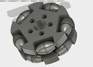
3d designing in fusion 360- Designing omni wheel
Designing Onmi wheel
i want to design omni wheel in 2 parts one is roller and other is rim so i design them separately and i used parametric design mode for making this wheel
In my design i have to use wheel which can move in both x and y direction , during discussion with regional guru, i was suggested to use omni wheel for my project which i am designing in this week , i am making parametric design in which i am
using only 2 parameter outer dia of wheel and inner dia of wheel so one can make any size of wheel just by doing modification
modifications
1 this is reference design with fixed parameter i am using this to make parametric design
2 this design there is no option to insert omni roller so i am giving this option in my design so one can easily prototype and do assembly
designing hub
1 let first go to modify and take two parameter inside dia and outside dia with od and id and assign them a valve now we use this two parameter for assigning value to all dimension in our design
1 sketch of inside section of omni wheel that is onmi wheel hub here use see value in fx because in dimension box i type directly od and od/2 for outer and inner circle respectively so it take valve in reference to assign parameter
3 Now press pull inner section by 0.3189*od as i have to assign it value of 19.138 mm so i divide 19.138/60 it comes out a figure of 0.3189 so i use this factor for getting my dimension and this is how you assign every value in reference to assigned parameters
4 now i am making upper section disc and press pull in opposite side that by using parametric parameter i.e - 0.1*od it comes out to be 6mm for this you have to sketch and press pull
5 In the similar way we make disc at another side by using same parametric dimension
6 Now you can see we have disc both side

6 Now we want to cut side slot where we are going to put our omni roller for this make sketch on one side using parametic dimension of 20 mm (0.33333*od )
7 Go to extrude command where select cut and extrude this you will get section side cut from one side
8 go to create select circular pattern where assign 5 so you will get 5 same slots in circular array
9 for another side we first make circular array using our sketch on another side plane than we give cut command to all this as this is another way to doing the same what you did in previous step7
10 go to extrude cut command and give them a cut so you will get as hub shown below
11 we have to design a slot from where on can insert a omni roller into hub , i 2mm distance both side for inserting and designing this from inside section you it will not come out and cutting part is hidden and array this in circular manner
12 I extrude cut this which you can see below
13 After this just select circular array from create < pattern and extrude cut in array
14 Make similar pattern on another side using same commands as shown in previous steps and our design of hub is completed
Designing side roller for omni wheel
1 we want a wheel in which just by changing outer diameter you can get different dimension of wheel so again we are using same parameter i.e od of wheel so before starting sketching go to modify set od paramenter and assign od=60 mm
2 Go to sketch and design sketch
3 After designing sketch go to revolve command in modify and revolve sketch around center line
4 Design a circular rod in another window which we will import in out part to make roller assembly
5 Insert a component in your roller design just by dragging that into your design
6 This is final design of roller
in this week i want to design this wheel in two 3d parts in fusion 360 which i did successfully and for further exploration i did more work on its design in coming weeks using simillar concept i design the wheel for my final project which you can find in project development week
Using same design for concept , i made 2d drawing files and and make onmi which you may refer week 4
using same design concept i Redesigning complete omni wheel for 3d printing, you may refer week6
designing another wheel in week 10 refer week 10
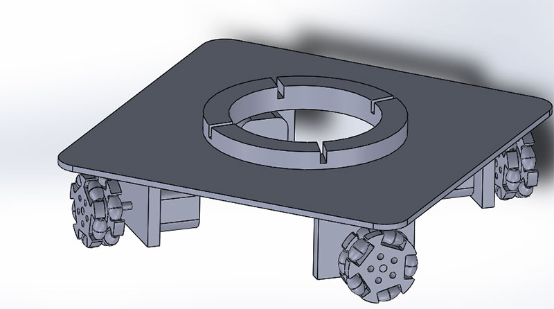
3d cad model of final project
i design 3d cad model of my bot for reference so that i get understanding of my design fies for this are added in top of this page , this model i design in solidworks
Experience with fusion 360 and comparison with solid-works
AS i have used solid-works earler so my regional instructor to write my experience with both , in my views both software have there good things ,
what i like about fusion 360
when we comparing part modeling and sketch designing i like fusion more good than solidworks as it have more friendly interface for this and all tools in easy access with left click on mouse and
what i don't like about fusion 360
1 when you are making any assembly kind of this i recommend to go for solid works as when you import two component for assembly in fusion you may find dificulty in joining as you need to specify different joint and set proper orientation but if you import same in solid-works you may get them join only by mat tool just set orientation
2 in fusion it create lots of bodies each time when we extrude any sketch it create diffent bodies so it is difficilt to check design for correction in complex design models

This work by Gaurav wadhwa is licensed under a Creative Commons Attribution-NonCommercial 4.0 International License.