

Week 10 Molding and Casting
Assignment
Group assignment:
Review the safety data sheets for each of your moulding and casting materials,then make and compare test casts with each of them Group work link
Individual Assignment:
Design a 3D mold around the stock and tooling that you'll be using,machine it, and use it to cast parts
Checklist
- Explained how you designed your 3D mould and created your rough and finish toolpath for machining
- Shown how you made your mould and cast the parts
- Described problems and how you fixed them
- Included your design files and ‘hero shot’ photos of the mould and the final object
Task for this week
1 Design the two part positive mold considering machining tool diameter and material
2 Making toolpath for cnc milling of mold
3 3D milling on shopbot CNC
4 Making of Rubber mold from CNC mold
5 Cast multiple objects from rubber mold
Learning from this week
1 Understanding concept of molding and casting
2 Learning process of 3d Milling mould pattern on shopbot
3 Process of mold making and casting
Files for this week
1 Stl file of mold
2 Fusion file of mold
3 CNC Finishing toolpath .Sbp file , toolpath gcode
4 cnc roughing toolpath .Sbp file , toolpath gcode
Group Work
In group Work we all together experiment with different material and making cast out of different material by refering there data sheet and my contribution in that is help teammates in casting Group work link
About this Week
This week is about molding and casting let first understand their definition
Moulding is the process of manufacturing by shaping liquid or pliable raw material using a rigid frame called a mould or matrix.
Casting is a manufacturing process in which a liquid material is usually poured into a mould, which contains a hollow cavity of the desired shape, and then allowed to solidify. The solidified part is also known as a casting
(source wiki )
the advantage of using this process for manufacturing i that once you make mould you can easily cast many pieces out of it
Process
for molding and casting we go through 3 steps as we want to make rubber mould with which we cast multiple number of pieces in industries during injection molding process is two step
Step 1 : Making positive mould / pattern : By machining of hard material such as wood, plywood, wax blocks, etc
Step 2 : Making Negative mould from positive: This can be made by pouring liquid and somewhat flexible material or with such material that can be used to make multiple parts (casted) out of it. For example Rubber mould
Step 3: Making body from negative mould in multiple : Here negative mould can be used to cast multiple part out of it by pouring end product material such as liquid plastic, ceramic etc.
Important links
1 Nils lecture on moulding and casting
3 Free 3D and 2D CAD Models you may find electronics component cad model also
4 How to read safety data sheet
Referance
Here are some work of past year student on similar thing
2 Casting rubber over mdf wheel
3 Wheel casting on wax and urathan
4 Caster wheel nicely done
5 Wheel casting using smoothcast 305
6 Casting wheel with transparent material nicely done
i did most of my other week assignment work on wheel so this week also i tried making wheel using moulding and casting process but this time i again design new wheel cast that , i do also want to use wheel in my final project so this work will be helpful in that , here i am making two part mould which combine to give wheel geometry here i am making one positive mould and my wheel is symmetric aboout centre line so i cast two negative mould from it and join them to make single body
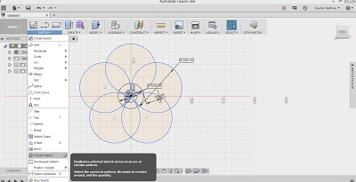
Designing of Wheel in fusion 360
Steps of Designing
.jpg)

.png)
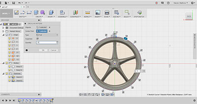
3d Model of Wheel
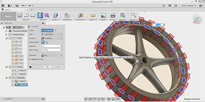
Designing Mould Pattern
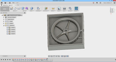
for making positive mould you need object /body ,now created side boundary around object and press pull/ extrude this to half here my wheel is symmetric around centre line so i design
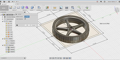
3d Model of Mould Pattern
Pattern 1
Pattern 2
Pattern 1 You can Mill this and add side walls later as it is easy to remove walls once rubber mould is solidified in this case
Pattern 2 This is complete mold in which you need to pore rubber for making negative part but in this it is difficult to remove
rubber it is advisable to use second one
Making toolpath on partworks 3d Software for 3D milling on Shopbot CNC
For 3d milling on shopbot we need .stl format file which we import in Partworks 3d software which will generate toolpath based on the geometry of file
Shopbot Interface consist of 7 steps with different set of instructions but we are not using cutting so here i am skipping that step
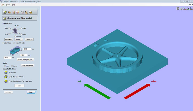
1) orientation and material size
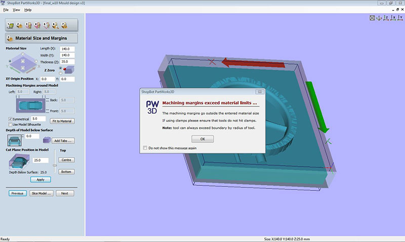
2) Material size and Margin
3) Roughing toolpath
4) Finishing toolpath
5) Toolpath preview
6) tool path save
Importing object in Partworks 3d
1 On opening partworks 3d it ask you to import file in .stl format and go next to orientation and size model, here it automatically takes body size select top surface for machining
2 now select material size and margin here select left corner as origin and set xy origin at (0,0) and margin of 5mm
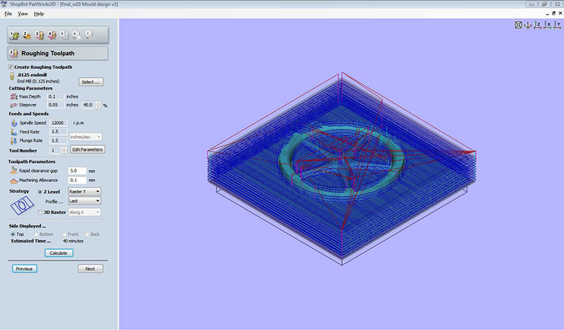
3 roughing toolpath , here we set parameter for tool selection which is based on your design and material ,i used 1/8 inch endmill for roughing toolpath and all other values as shown in image below
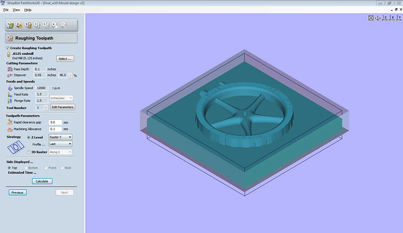
4 one you set all parameter now click on calculate to get time estimation and tool movement as shown by red lines below
5 now go to finishing tool path and set parameter for finishing toolpath
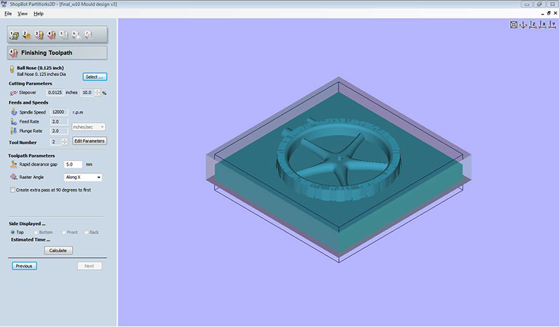
now calculate finishing toolpath
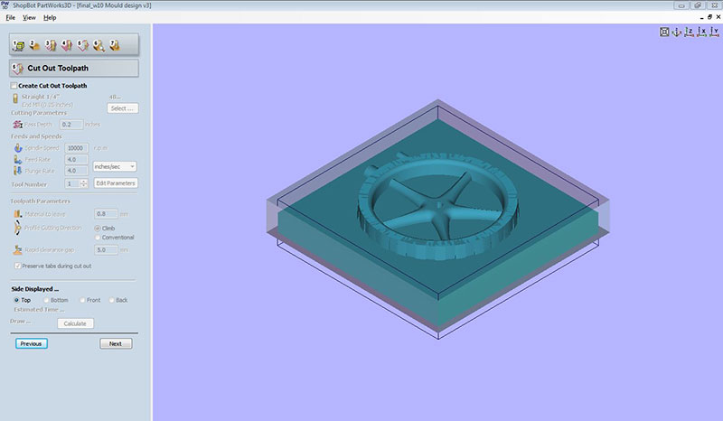
6 cut out toolpath as we skip this step here as we don't have cutting requirement
7 now go to preview feature and preview roughing toolpath

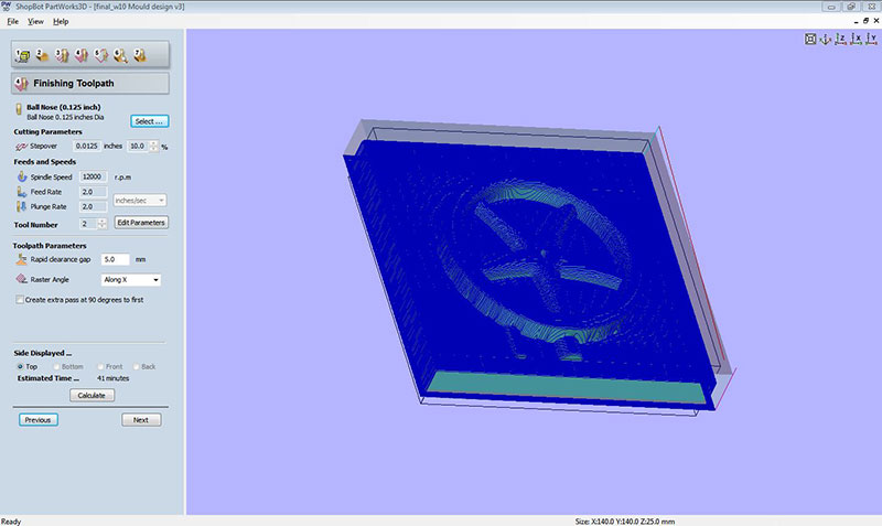
Preview of finishing toolpath
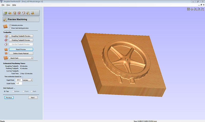
it will save file in .sbp format

Preparing Material for CNC Milling
One of my fellow used green mdf for cnc milling and he found very good result with that and we have lots of this pieces in our lab so used green mdf for mould milling i stack 3 mdf pieces two 15*15 cm^2 and one of 15*20 cm^2

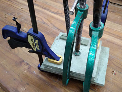
Setting Material on cnc Bed
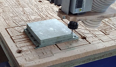
you have to clamp material tightly to bed as i used machine screw to clamp my material once material is clamp you need to set origin which is at one of the corner of your material for this you need to set certain control on shopbot software
Setting Control on shopbot software
Here i am using shopbot software for operating machine the steps are shown in gif image
1 setting origin and run warm up
2 loading toolpath
3 starting spindle before cutting
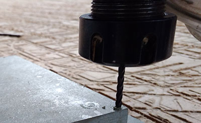
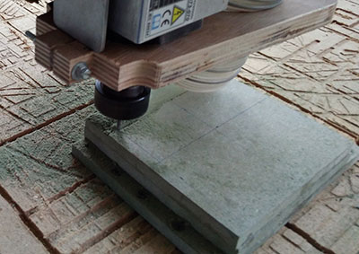
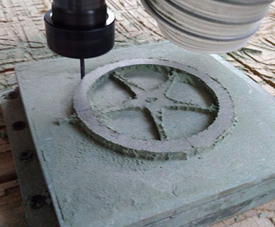
Milling Process
you need to load roughing tool path which we made once it start it start milling the body as shown below
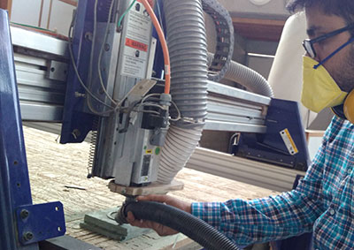
while milling you need to take care of wearing mask and headphone and here i am also using dust collector for collecting dust

Roughing process

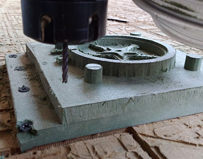
Failuers and Correction in this process
As i mill all boundary surface around my 3d model in roughing process and now i have to change tool and set another milling bit for finishing toolpth but i lost the origin point now my origin is in air and i am not able to locate correct position, as (x, y ,z) all three coordinate lost
How i lost my origin
while changing tool i stop machine and remove the tool from tool holder in process of removing machine tool head is moved from its position manually
Steps i did for correction in first time
i repeat the same process and again start milling my object , this time i did not switch off machine while changing tool, so my origin position i.e (x,y,z) coordinators remain same (as in tool head can't move manually while machine is now you can only move that using machine control ) but again i failed in this process

Reason for failuer in second time
As the tool length which go inside the collate is not same for both Roughing and finishing tool path so when i changed the tool may be this time both length are not same so AS (X,Y) origin is fixed this time but z varies as tool length varies
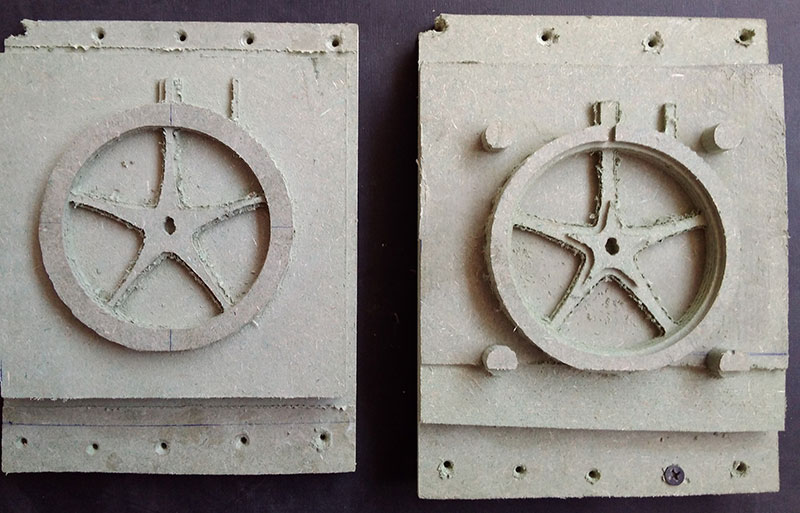
Correction for making mold again
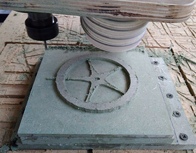
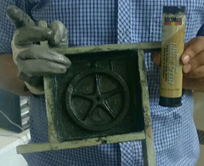
This time i made side boundary around my design so this boundary remain even after milling process and at this position i can set tool origin for finishing process ,this is good decesion and i successfully milled my object
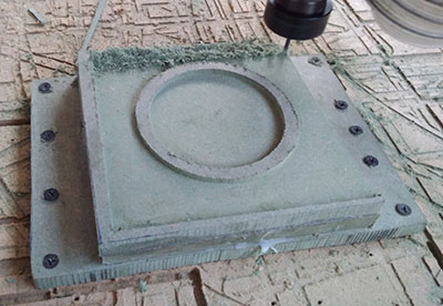


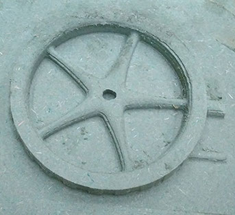
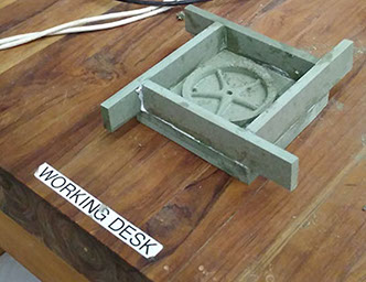
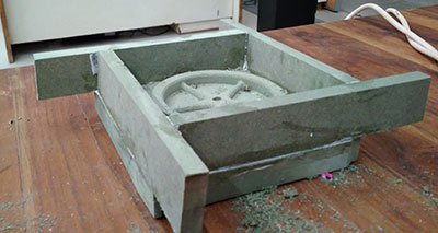
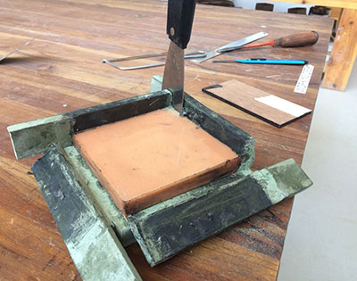
Now at the corner i fix my origin that i used for both roughing and finishing path so this time i get proper finished mould and i cut the side manually and fix removable four sides so that i can detached them easily
Preparing Negative Rubber Mould
there are few steps in preparing negative rubber mould
step 1
the first step here is to apply realising agent on mould ,i have mix oil , sope solution and lithium grease mixture in approximate ratio of 2:1:2 respectively , in this apply more grease as this is really good and also apply more at corner position
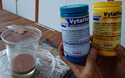
Step 2 prepare mixture of rubber solution
for preparing mixture of rubber solution you have to mix two compound as per direction given on their box here i used urathane vetaflex-40 so i mixed them equal by weight as shown below
Safety data sheet of vetaflex -40 / Molding Material
safety data sheet of compound is the data sheet prepared for the safety measure regarding the use of compound here we are using Vetaflex 40 the complete data sheet of this is here
i am writing here the first aid measure but you should refer complete document from above link
Inhalation: Remove source(s) of contamination and move victim to fresh air. If breathing has
stopped, give artificial respiration, then oxygen if needed. Contact physician immediately.
Eye Contact: Flush eyes with plenty of water. If irritation persists, seek medical attention.
Skin Contact: In case of skin contact, wash thoroughly with soap and water; remove
contaminated clothing and launder before reuse; seek medical attention if rash develops.
Ingestion: Do not induce vomiting unless instructed by a physician. Contact physician
immediately
After first aid, get appropriate in-plant, paramedic, or community medical support.
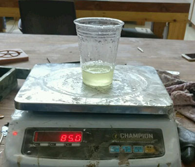
Steps for mixing compound
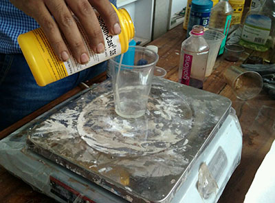
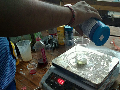
for this first put empty glass press 0 than pore compound A to certain limit here 85 gm than press 0 again and pore compound B to certain limit here 86 gm (nearly 85)

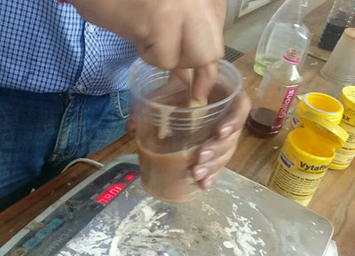
Step 3 stir the mixture for atleast 2-3 minute as you see diffrence in color of mixture and it turn to light brown
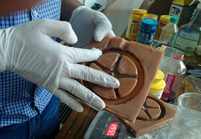
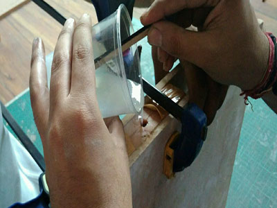
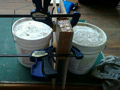
Step 4 Pore the material in the mould as shown below for this first pore small cavities in your mould than outside to that so that air will not get trap in your cavity and keep it for atleast 16 hours as setting time given in instruction


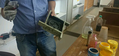
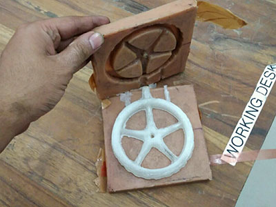
Step 5 Demoulding your mould this is process of separating mould , here i used fevicol for fixing side walls so this can be easily removed as shown in figure , this become really difficult thing when you give side wall in design as you need to cut them for getting your mould out ,i learn this thing from my fellow tanveer

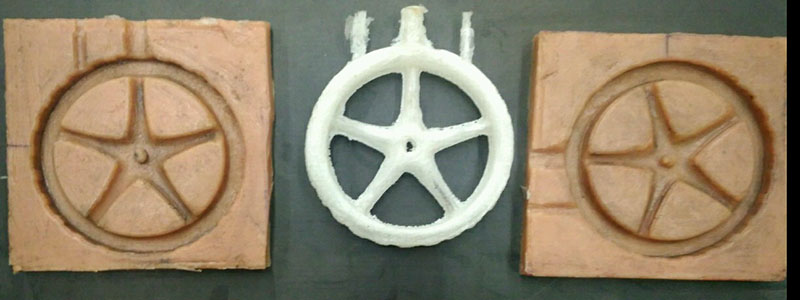
Making second Part of negative mould
using similar process i made another mold using same positive mould by again fitting this side walls on its place using fevicol and this time their already grease on mold so i applied little more on it and repeat the same process again .

Casting plastic wheel out of negative urathane rubber mould
casting is third process in which we finally make our wheel and for casting process you need to follow some steps which i have shown below as
safety data sheet of smoothon 325 / casting material
here i am writing first aid measure you must go through complete data sheet before using this material from here
Inhalation: Remove source(s) of contamination and move victim to fresh air. If breathing has
stopped, give artificial respiration, then oxygen if needed. Contact physician immediately.
Eye Contact: Flush eyes with plenty of water. If irritation persists, seek medical attention.
Skin Contact: In case of skin contact, wash thoroughly with soap and water; remove
contaminated clothing and launder before reuse; seek medical attention if rash develops.
Ingestion: Do not induce vomiting unless instructed by a physician. Contact physician
immediately
After first aid, get appropriate in-plant, paramedic, or community medical support
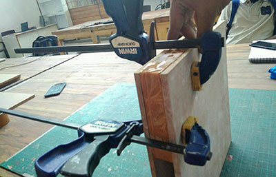
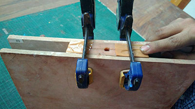
Step1 Apply cast removing agent i used here Vaseline as suggested by fellow fabacadmey student Adtiya

Step 2 Seal your mould ,i used tape for this and two mdf inbetween which i fixed my mould as shown below
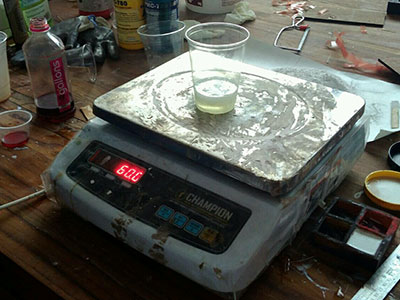
Step 3 Mix the Smoothcast 325 Part A and Part B in equal amount by weight here we are pouring 30 gm of A and 30 gm we put compound A first for this place empty glass and zero the scale than pour 30 gm material

Step 4 mixing the another compound B
Step 5 steering the mixture for 2-3 minute and keeping the mould straight

Step 6 leaving the mould in the same position for 24 hours
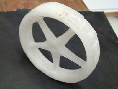
Finishing Process
1 For finishing the part i use dremel tool
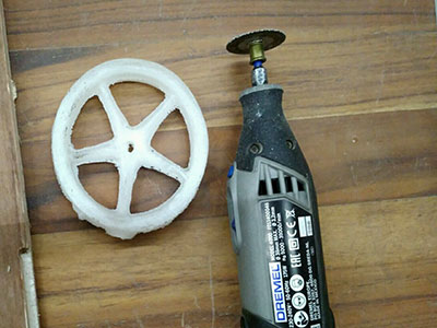
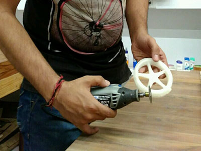
2 Hero shot of final Product made

Conclusion
This week is fun learning for as i am mechical engineer i did sand casting in my college but here casting with rubber compound and making mold using 3d cnc is new experience for me, i explore many things and i am happy as in the end i get desired result as my wheel is ready ,i find some areas of improvement in this which i will consider for next time but overall experince of doing this is really good , for sure few things which i find important check data sheet and wear safety items as gloves , mask as it is for your safety before using any casting material .
Areas of Improvement in design and process
1 In my design of mold , I made runner and riser position at center of periphery of wheel and also which is wrong as you see i got notches , Mark of runner riser on periphery which affect the smoothness of wheel on moving , you should give position of runner and riser on top on any side
2 For better Mold locking of 2 part mold , Design impressions interlocking patterns in design on both sides ( one part positive and another part negative ) as this will help in locking two part easily
3 Use vacuum machine as suggested by my global evaluator as you will have fewer bubble and better result .

This work by Gaurav wadhwa is licensed under a Creative Commons Attribution-NonCommercial 4.0 International License.