Abstract
This week was about programming the board milled and soldered 2 weeks ago.
Some of the question raised were:
- How to establish a connection with a new board?
- How to track boards malfunctions?
- What is embedded in an Attiny44?
- What I/O latitude does a Attiny44 have?
- How to reorganize/optimize the board?
I mainly used 1 workflow:
Arduino IDE > Avrdude
My biggest achievement: Perseverance
My biggest struggle: The troubleshooting and the tedious soldering
Chronology
| Thursday | Friday | Sunday | Monday | Tuesday |
|---|---|---|---|---|
| Introduction to Attiny | Arduino as programmer | Communication with Arduino | Board testing | |
| First board tests | New board milling | New board soldering | Resoldering/Multimeter diagnosis | |
| Documentation | Blinking |
Setup
| Softwares | Fonction | |
|---|---|---|
| Arduino IDE | Programming and televersing interface | |
| Avrdude | Downloading/uploading the ROM and EEPROM contents of AVR microcontrollers | Integrated in Arduino IDE |
Skills acquired
Asssesment validation
Avrdude setting
Avrdude is an open-source utility to download/upload/manipulate the ROM and EEPROM contents of AVR microcontrollers using the in-system programming technique (ISP). The commands are quite easy. We were manipulating a t44 (-p) with an Arduino/stk500v1 programmer (-c).
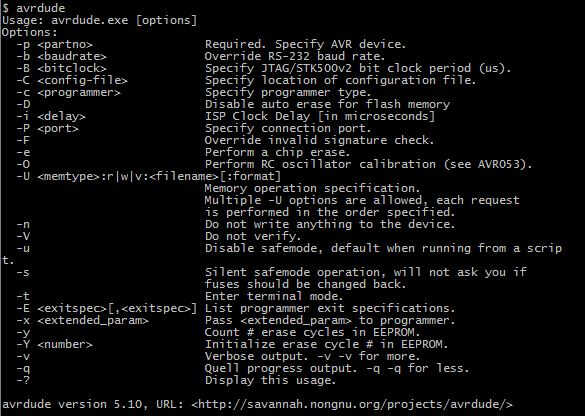
Avrdude command list

Avrdude setting: programmer list (-c)
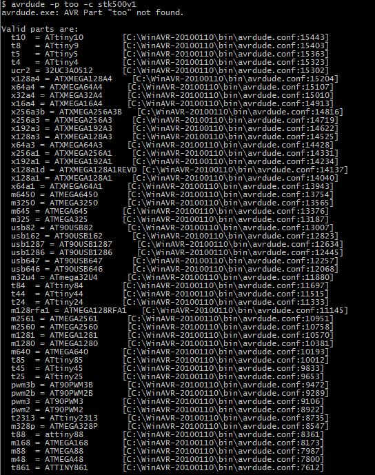
Avrdude setting: AVR list (-p)
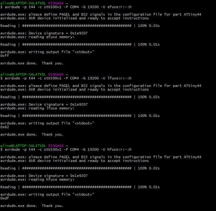
fuse reading
Arduino IDE setting
I then tried to get familiar with Arduino IDE as its interface is quite nice. Arduino IDE also provides additionnal functionalities such as programm checking and compiling.
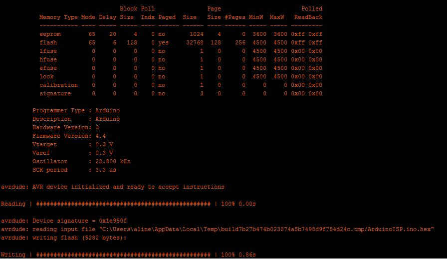
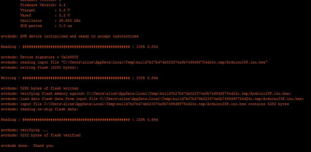
The first step was to turn our Arduino into an ArduinoISP. Such a sketch can be found in the example library. Only the Arduino need to be plugged for this uploading.
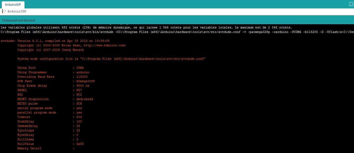
Arduino into ArduinoISP(1)
Arduino into ArduinoISP(2)
Arduino into ArduinoISP(3)
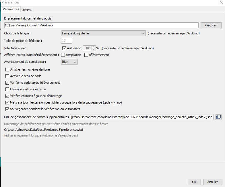
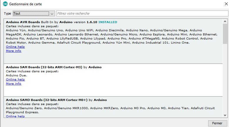
Once done the Arduino can be wired with the hello board. To select attiny microcontroller a package needs to be added in Arduino IDE. To do so an URL (githubusercontent.com/damellis/attiny/ide-1.6.x-boards-manager/package_damellis_attiny_index.json) needs to be added in the File> Preferences> Card manager. Now attiny cards can be found in the Tools>Board list. I opened the Blink sketch provided in the Arduino examples. Changed the Led Pin to 11/6 (in function of the hello board i used) I ticked ATtiny 24/44/84. As Processor I picked ATtiny44, as Port: COM4 and as Clock: Internal 8MHz.
Arduino setting
Arduino setting(2)
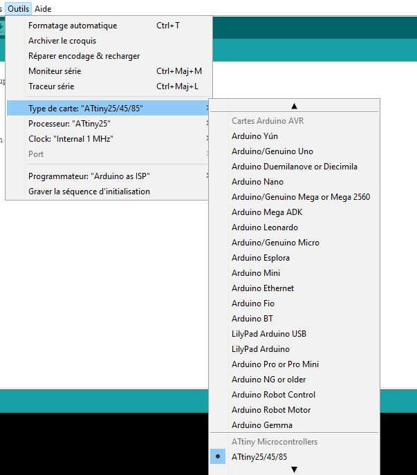
Arduino setting(3)
To upload this sketch in my ATtiny44, I went to Sketch > Upload using Programmer. Would I have wanted to change the clock into an external one, I would have needed to select another clock and to Tools> Burn Bootloader first.
I always faced the same issue with Arduino IDE. When I used Arduino as a programmer the USB port becomes problematic.
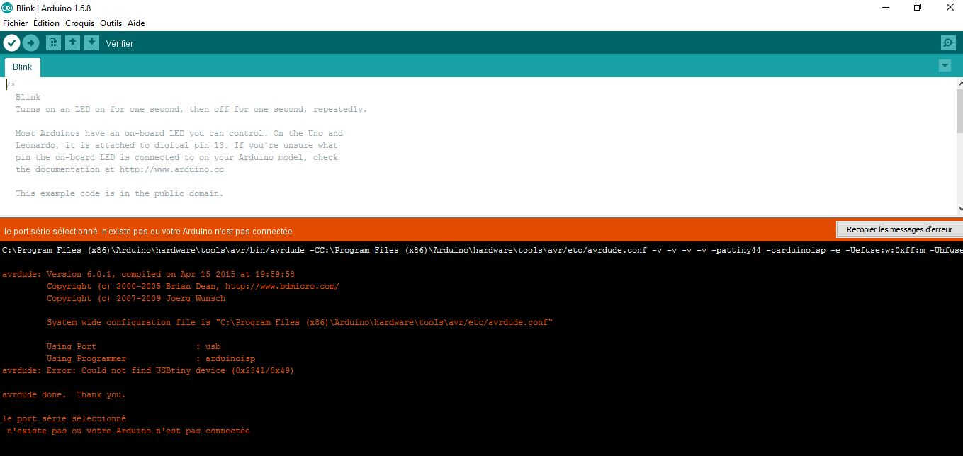
usb port issue
That's why I stopped using Arduino IDE for uploading but I kept using it as compiler. I uploaded with Avrdude commands(avrdude -p t44 -c stk500v1 -P COM4 -b 19200 -U flash:w:File.hex:i).
Preparatory work
After Thursday lecture given by Roman, we tried to establish the connection between a programmer (UsbAsp) and my hello board. We encountered several obstacles and we had to switch to Avrdude for more direct interactions. We tried to read the flash memory, to write on it and to set the fuses to account for the external clock. The conclusion of this work was:
- it is possible to write and read from the board
- The 20 MHz external clock doesn't respond -we used the internal 8MHz instead-
- it doesn't blink. Distrust regarding the component values and the soldering emerged, the orientation of the LED was also dubious.
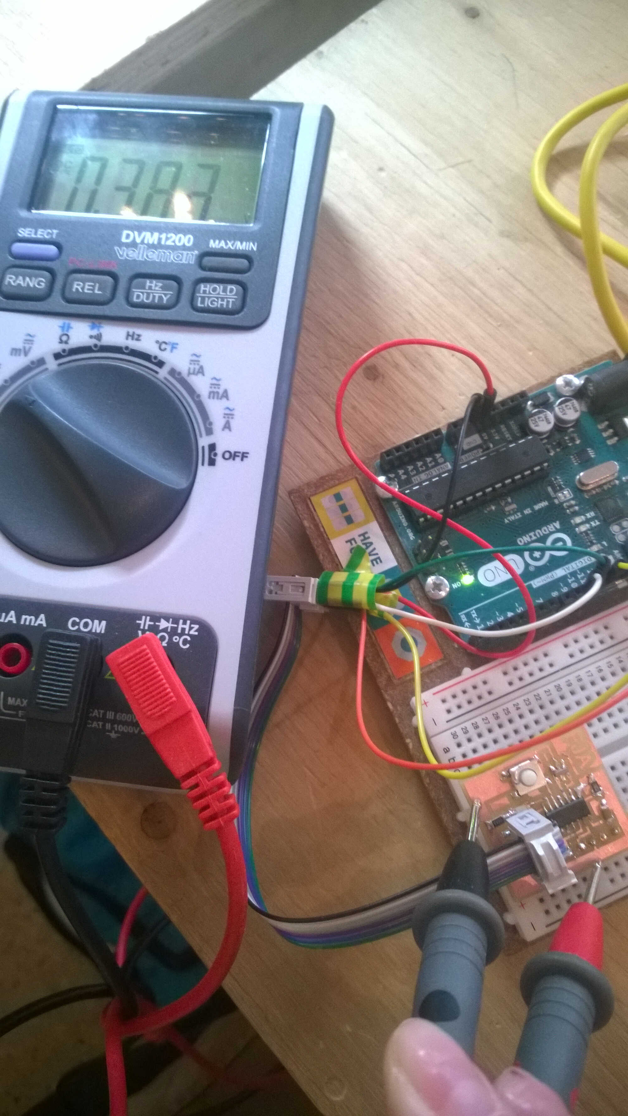
Multimeter
I learned to get the most of the multimeter this week: to check the LED values and voltage drop on circuit, to check resistance/capacitances values, to check connectivity, to track short-circuits.
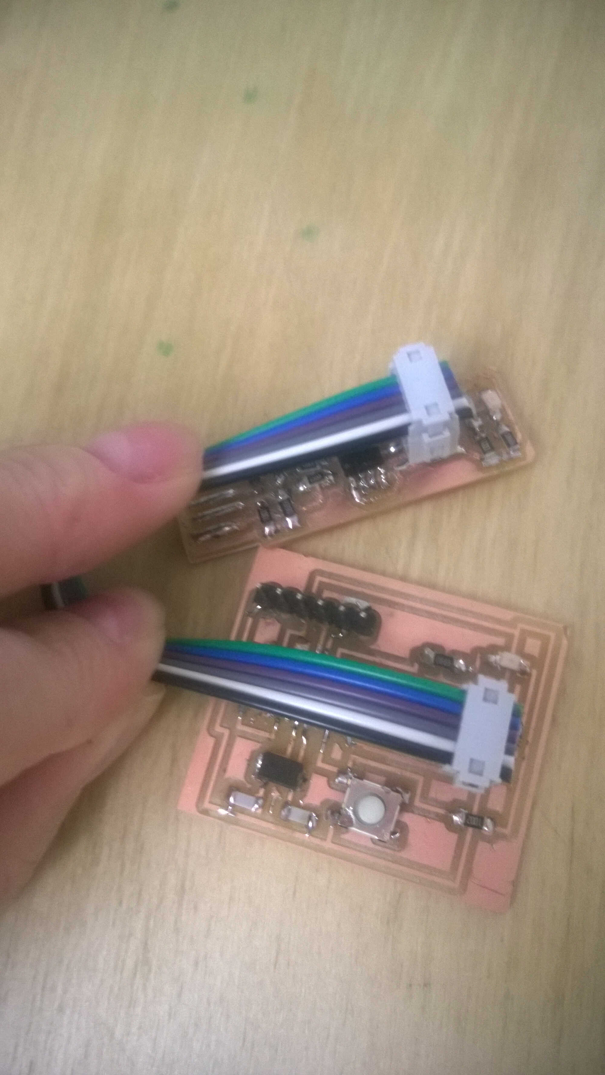
Below a board Thomas made, when comparing the ground and the VCC planes I noticed I didn't have the 5V difference.
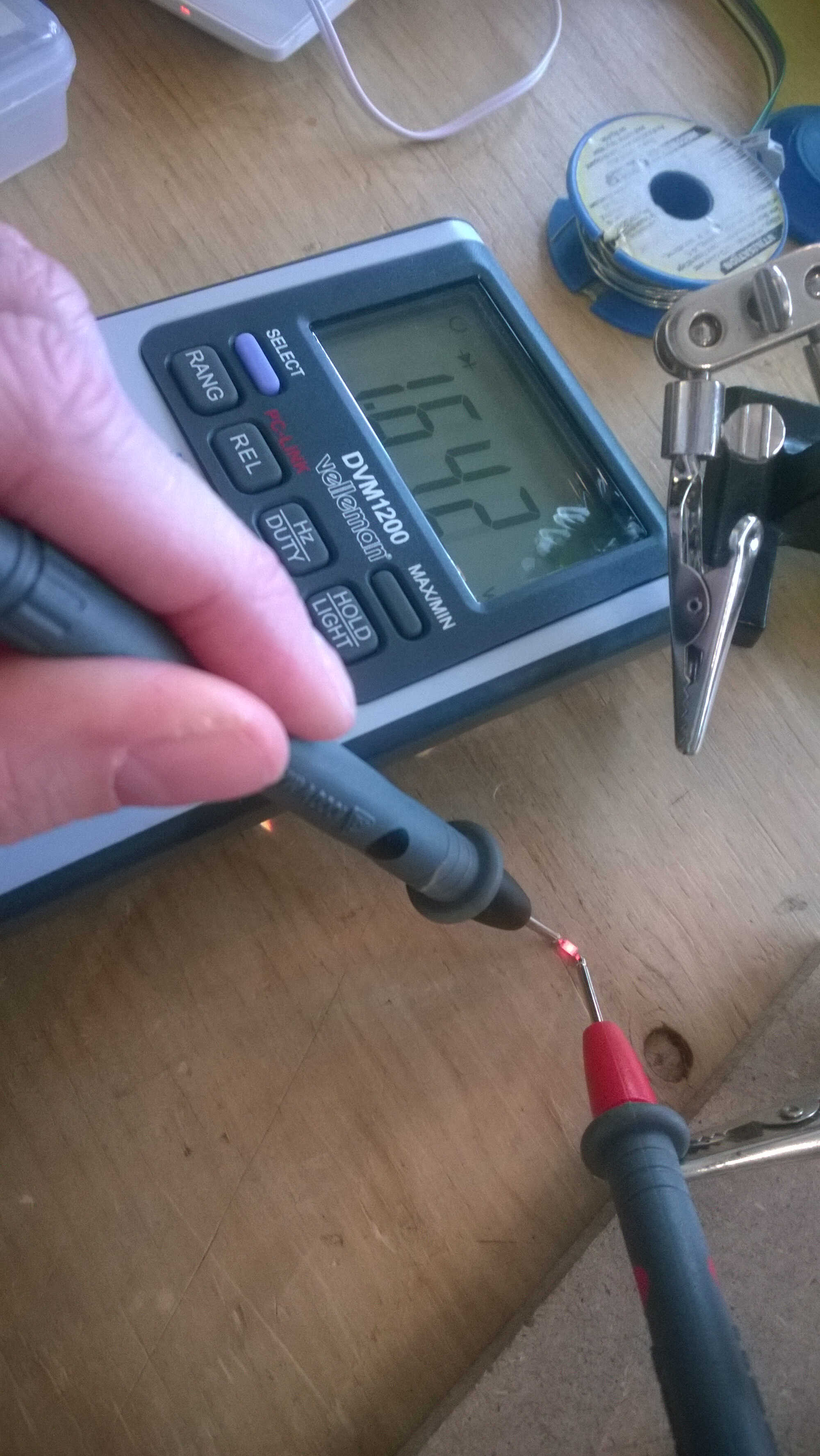
led voltage drop
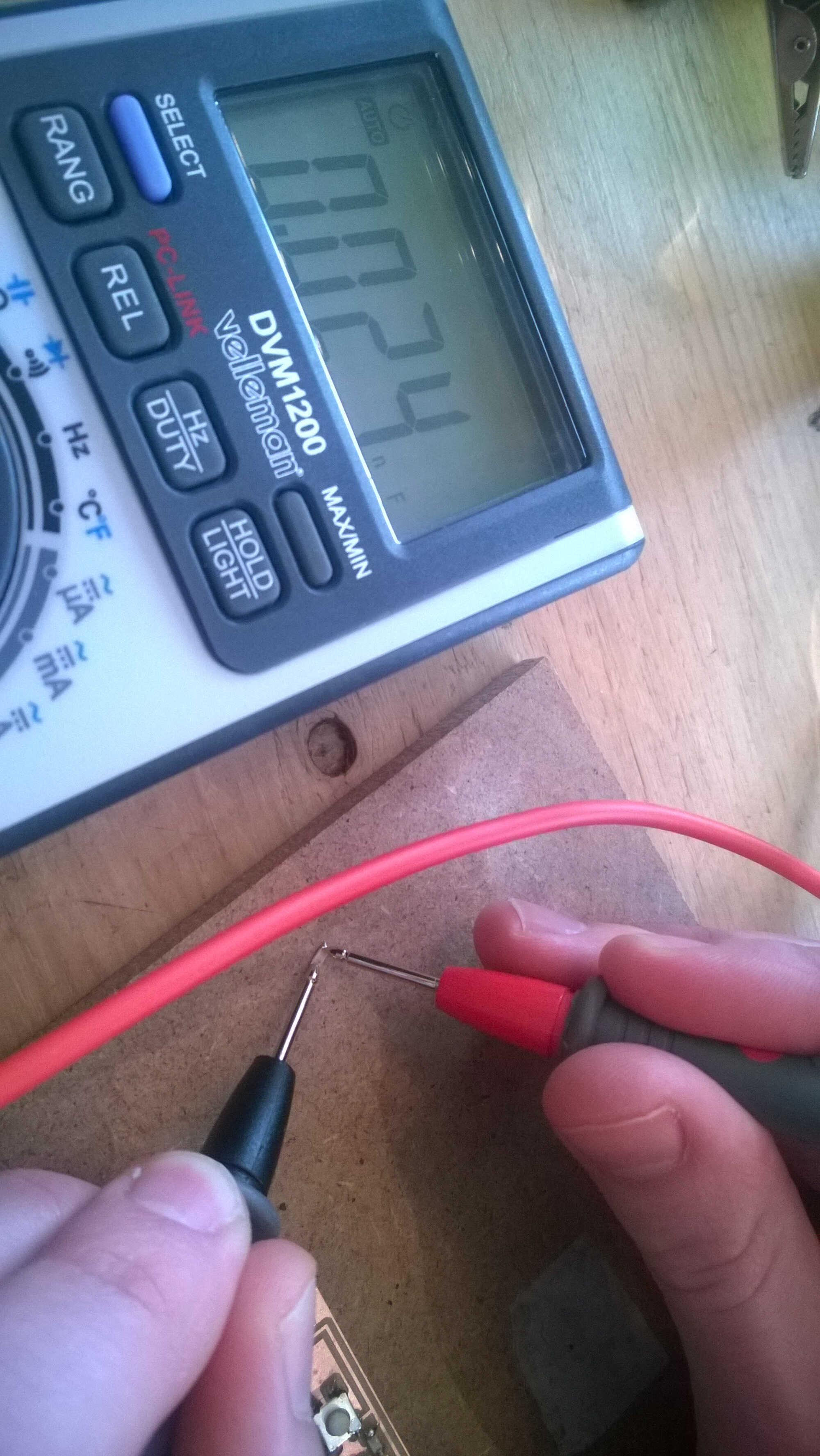
capacitance value check
short circuit
One solder was linking both planes. I tried to fix it by isolating it with a cutter without success, there might be another bridge I didn't spot.
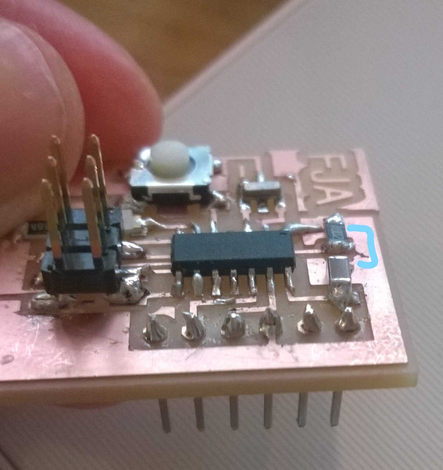
short-circuit shooting
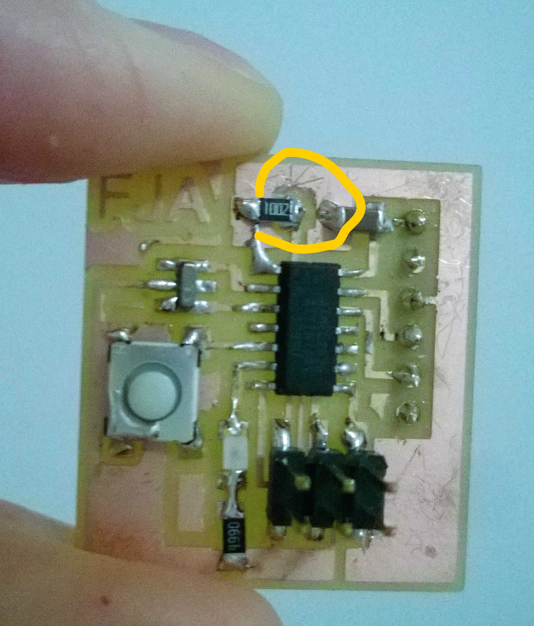
isolation with cutter
Wiring
In order to link the hello board to FabISP a ISP cable needed to be built.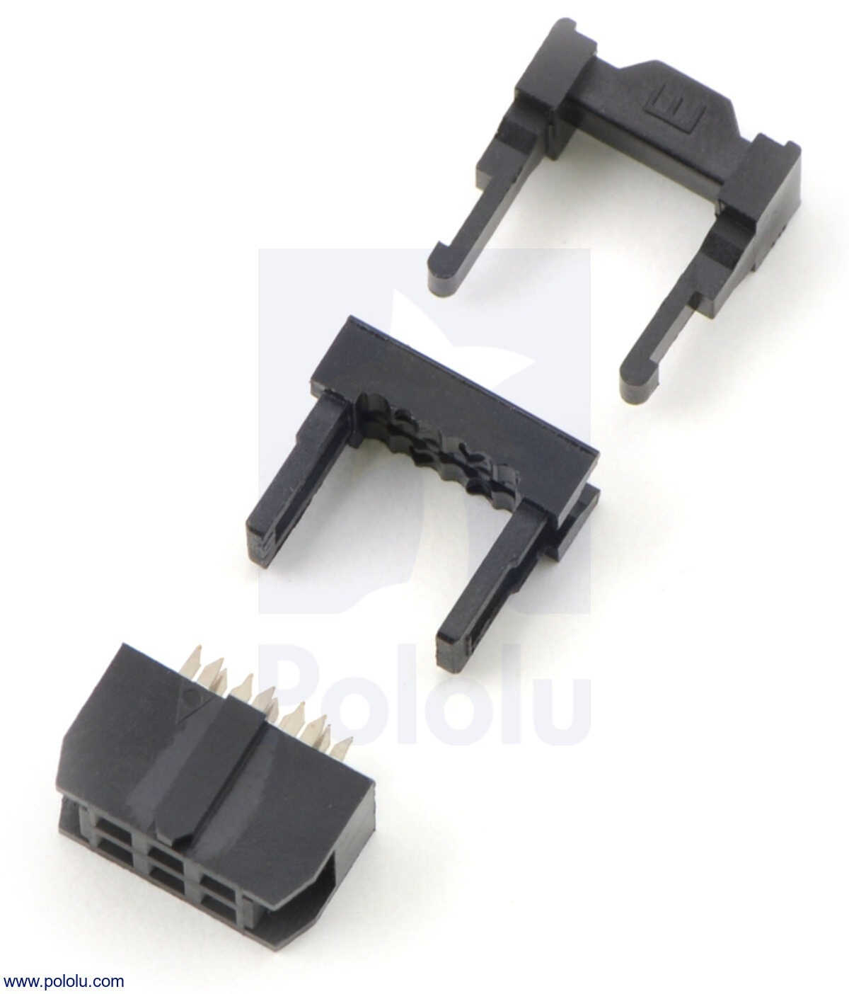
ribbon cable connector
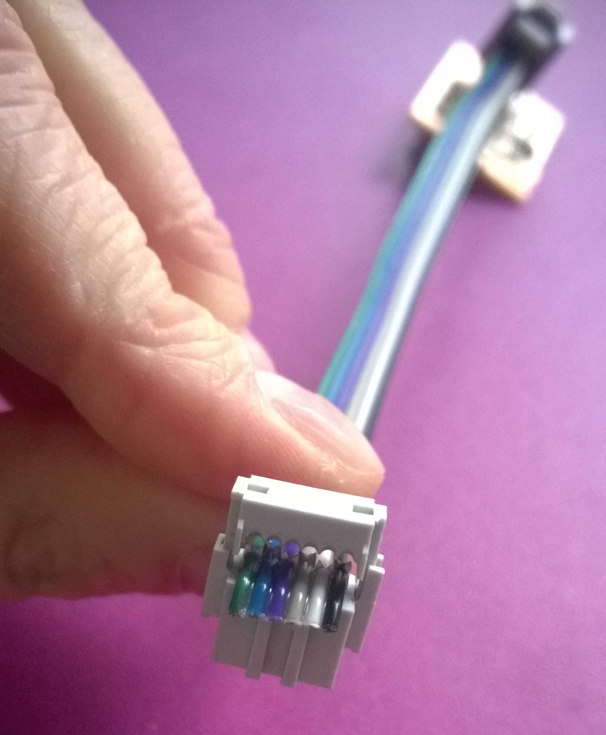
crimping cables
Fab to hello
By looking at the inside of the crimping connector it is easier the visualize which cable is linked to which hole. Here the black wire (ground) is connected to the back hole on the right side.
To remove the uncertainties linked to my FabISP, I decided to use my Arduino as programmer. The first question was how to wire the Arduino to the hello board. Through the ISCP or through pins? Arduino tutorial as well as the FabAcademy previous students recommend the second.
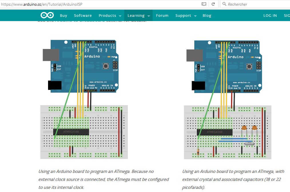
Arduino to board
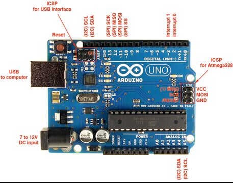
Arduino ISCP
Some doubts regarding the wires themselves emerged, they were replaced with wires without caps, which fitted better in connector and the powerage increased.
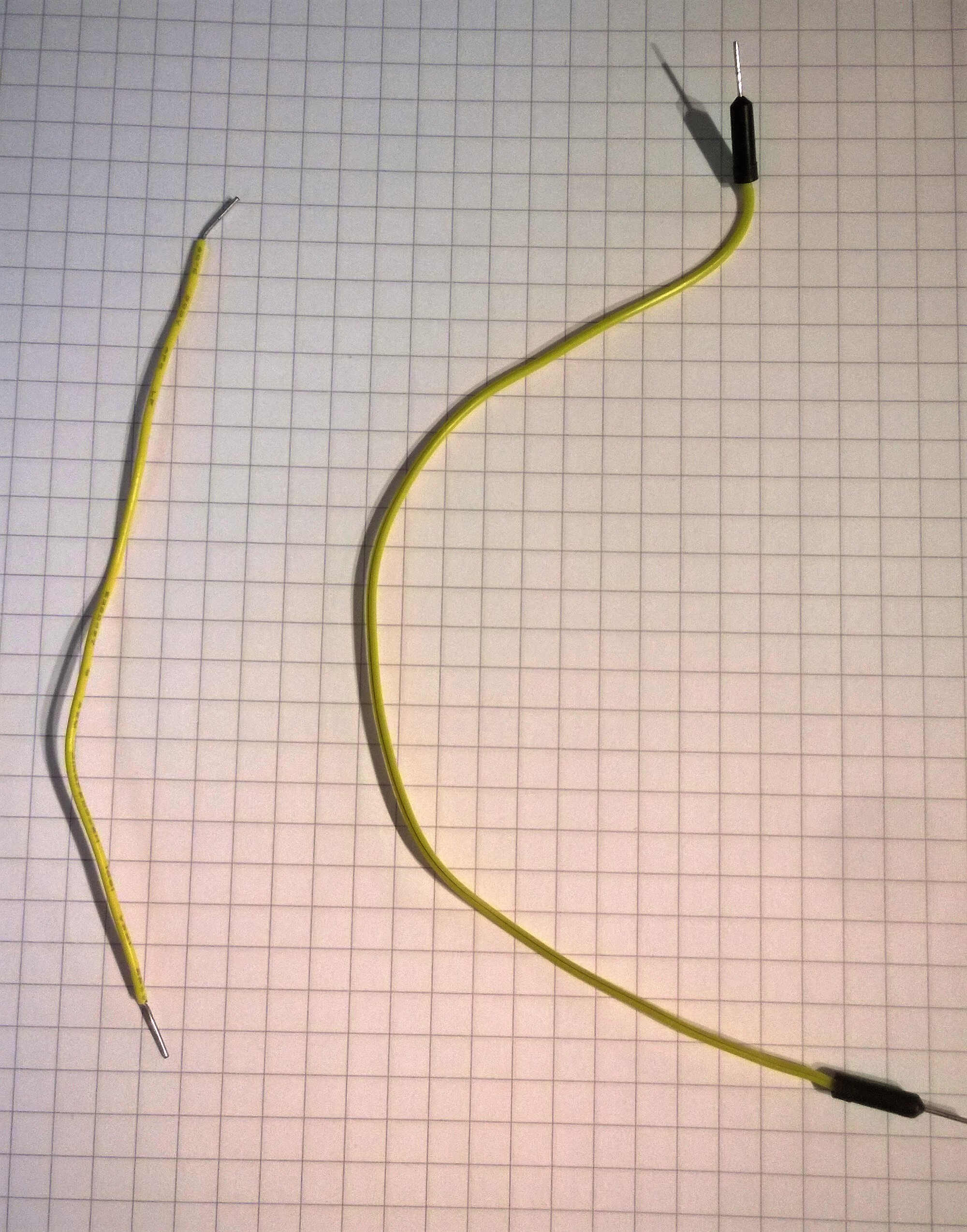
right wire type was replaced with the left one
New board
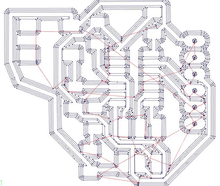
As no output could be obtained with my hello board, I decided to mill another board. As the external clock has been identified as a possible issue, I removed it and its associated capacitors in the schematics. I had to rearrange the board accordingly. I took that opportunity to test the autorouter from the start. I removed all the wiring and let the autorouter compute. I rearranged the component a couple of time for it to be able to reach 100%.

new board routed -notice the 45° wires-
fabmod vector
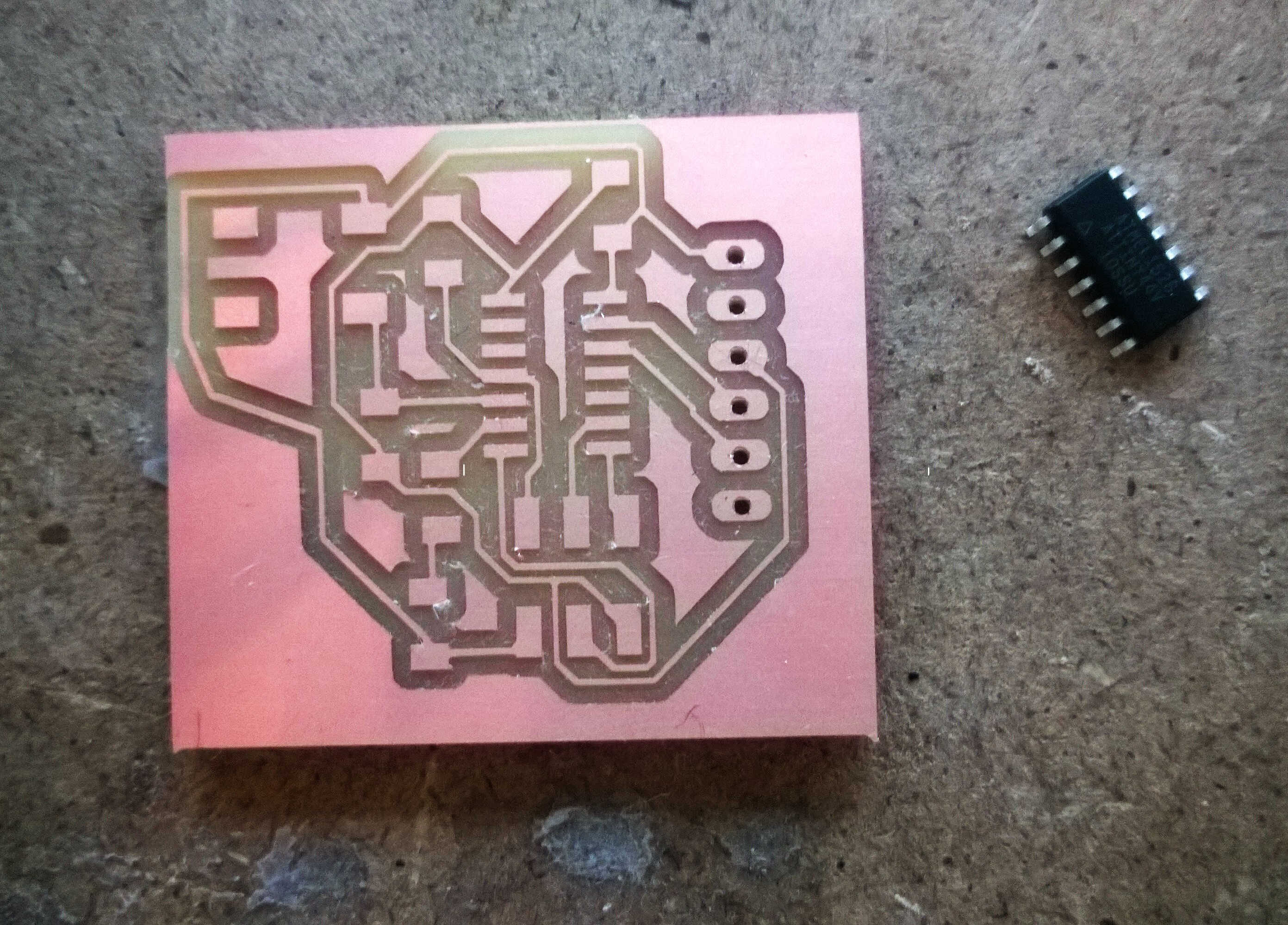
new board milled and cleaned
I tried different ways of programming and compiling.
Blink
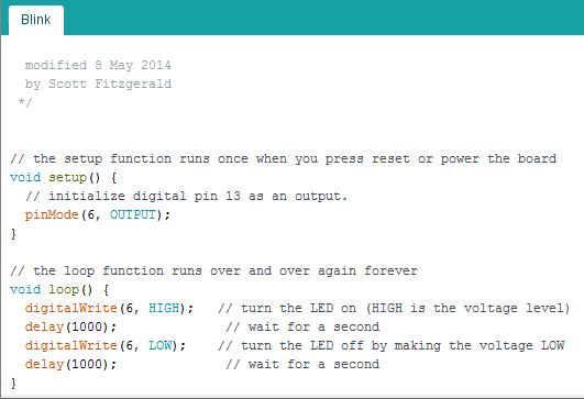
First I retrieved Arduino's example Blink. I just changed the pin number from 13 to 6. In the setup the pin 6 is defined as output. The loop switch the voltage on and off with a 1000ms delay between the 2 states.
I compiled this sketch in Arduino IDE and exported the 505 octets hex.
Arduino Blink
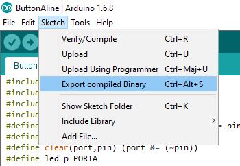
export hex
// the setup function runs once when you press reset or power the board
void setup() {
  // initialize digital pin 13 as an output.
  pinMode(6, OUTPUT);
}

// the loop function runs over and over again forever
void loop() {
  digitalWrite(6, HIGH);   // turn the LED on (HIGH is the voltage level)
  delay(1000);              // wait for a second
  digitalWrite(6, LOW);    // turn the LED off by making the voltage LOW
  delay(1000);              // wait for a second
}
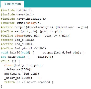
C Blink
              #include <stdio.h>
#include <avr/io.h>
#include <avr/interrupt.h>
#include <util/delay.h>
#define output(directions,pin) (directions |= pin)
#define set(port,pin) (port |= pin)
#define clear(port,pin) (port &= (~pin))
#define led_p PORTA
#define led_d DDRA
#define led_pin (1 << PA7)
void initIO(void) {     output(led_d,led_pin); }
int main(void) {     initIO();
while (1) {
  clear(led_p, led_pin);
  _delay_ms(1000);
  set(led_p, led_pin);
  _delay_ms(1000);    }
  return 0; // never reached }
}
At the start of the sketch libraries are included and macros defined. The pin 6 is defined by its data register (DDRA), its port (PORTA) and its name (PA7). In the setup the pin 6 is defined as output. The while loop switch the voltage on and off with a 1000ms delay between the 2 states.
After board checking and fixing the voltage issue, the code was wrote in the Flash but as the oscillator is an internal 8MHZ one, the blink can't append more often than every 8 seconds.
Button
To make the LED lights up as the button was pressed, I used a C code. This time the button is defined as input. A function readButton is used to output the button state.
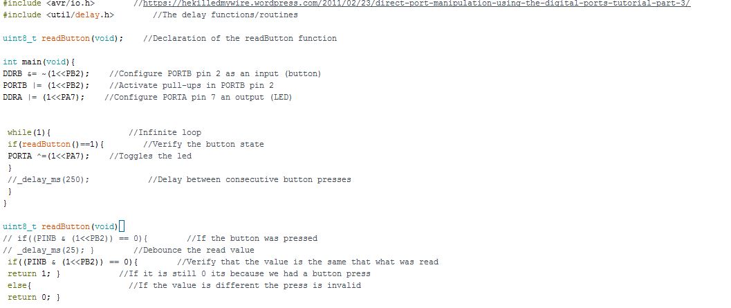
C Button
#include <avr/io.h>
#include <util/delay.h>

uint8_t readButton(void);

int main(void){
DDRB &= ~(1<<PB2);
PORTB |= (1<<PB2);
DDRA |= (1<<PA7);

 while(1){
 if(readButton()==1){
 PORTA ^=(1<<PA7);
 }
 //_delay_ms(250);
 }
}

uint8_t readButton(void){
// if((PINB & (1<<PB2)) == 0){
// _delay_ms(25); }
 if((PINB & (1<<PB2)) == 0){
 return 1; }
 else{
 return 0; }
clear bouncing issue
Source sketches to load here
My datasheet observations:
- All pins of the ATtiny haved pull-up resistances. So the pull-up resistance we use for the button now seems optional.
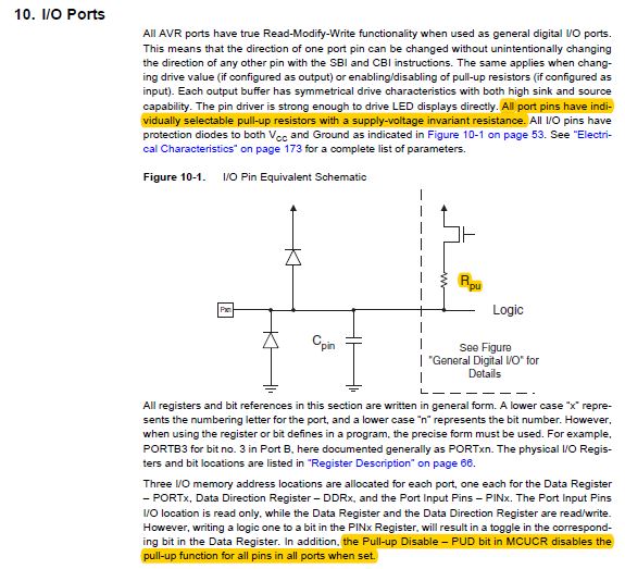
I/O pins pull-up resistance
- They are 2 kinds of PWM: a single slope (recommanded for power management) and a double slope one (recommanded for motors).
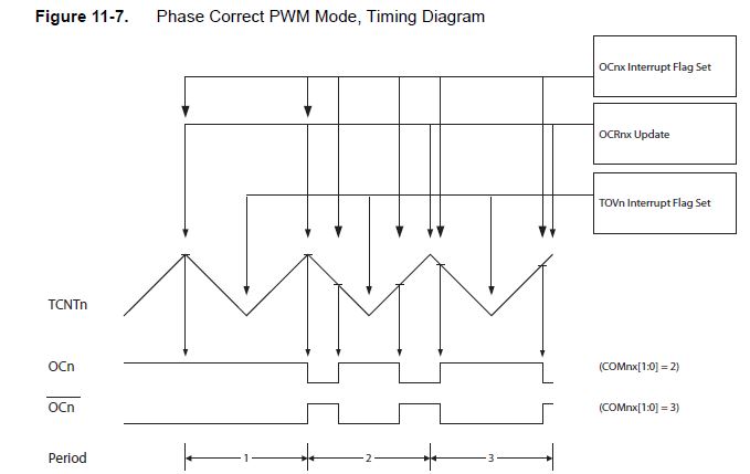
dual-slope PWM
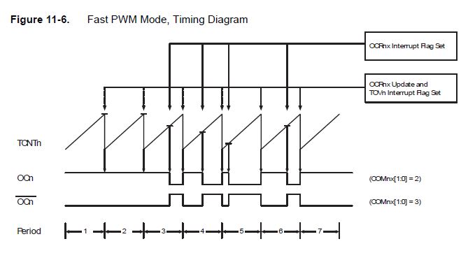
single-slope PWM
- A low voltage results in a Reset
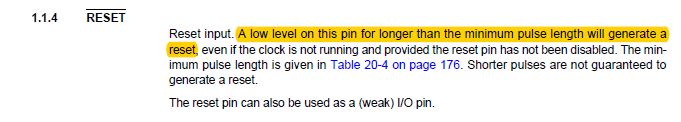
low voltage reset
-They are different power consumptions possible
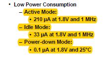
power consumption
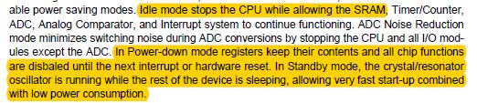
power consumption modifications
-AVR microcontroller can be turned into touch sensor
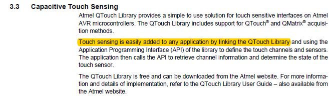
capacitive sensor
-A 32 registers organization
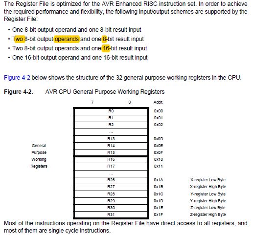
registers
-The 2 main langages are C and Assembly
- Multiple clocks are coexisting
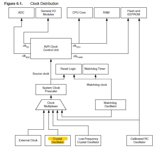
clock diagram
- The internal 8 MHz oscillator is aaproximative but can be calibrated by changing the OSCAL register. A 128kHz internal oscillator can also be used.
- Two types of counter can be used the 8 bit and the 16 bit one.
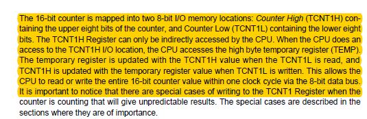
16 bit counter
- Events can be logged
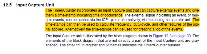
events capture
- The external clock should have some characteristics
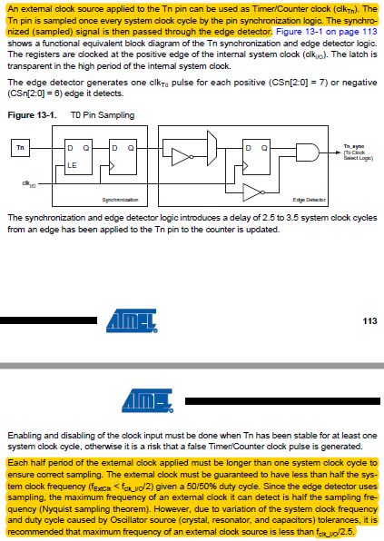
external clock setting
- Serial communication can be established in 2 (slew rate limiting, w/o noise filtering) or 3-wire mode. USI -universal serial interface- can also be used for other tasks (counter/interrupt).
- Lots of options can be switched off to reduce power consumption.
- An analog comparator is also provided by the AVR
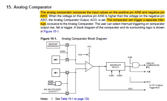
analog comparator
- An analog to digital convertor is wired to a nine channel multiplexer. The voltage reference for ADC is set to 1.1V. This process requires a certain frequency, if the clock doesn't meet the frequency prerequisite a prescaler is used. A conversion takes 13 clock cycles. High frequency components are no good candidate for ADC. It is possible to choose among 3 types of conversion (single ended, unipolar differential, bipolar differential). A temperature sensor on chip can be used in association with ADC.
analog comparator
- It is possible to debug on wire with AVR Studio.
- The Flash can self-programm itself.
- The signature bytes of the ATtiny44 is 0x1E 0x92 0x07. Its operating temperature range is -40° to +85°.
- There is a high-voltage serial option.
- In order to operate at the clock frequency the voltage needs to be high enough.
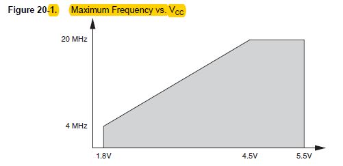
vcc requirement for frequency
In the next weeks I regularly used the knowledge I gained from the Datasheet:
- mainly in the input (temperature and phototransistor boards)/output weeks
- For the final project even if I used the ESP as microcontroller, similarities in the pin concepts were used
- The main concepts used were the digital vs. analog pins, the wiring to ISP/FTDI and the internal pull-up/pull-down resistance
Regional review
Embedded programming
- Use of Neopixels
- The use of commercial boards should be limited to the minimum
- Do not plug the reset wire with the FTDI cables
Personnal feedback
- Struggling is the best way to learn, well done
- Always write about lack of material (for example flux or thin soldering iron tips)
- There should be a cover to the week page
General review
Embedded programming
-Bootloader definition: brings programs through serial eliminating the need for ISP This is not compulsary, it is always possible to keep reflashing through ISP
- I am not the only one with FabISP issues
- C programs are lighter and without reference to libraries. It is interesting to compare code size. Assembly is the lighter -only hex files islower level- and doesn't require compiling.
- A hot board is a damaged one
- As I deduced from the datasheet no pull-up resistors are needed with the button
- The V pin of ISP is supposed to be an output-and to tell the programmer the voltage used- not be used for powering the board. The FTDI cable is the power supply. That's what I did wrong for the whole week!!
- Next time I will test GCC, GNU compiler -that's the compiler called by Arduino IDE-
- For each pin a direction and a port should be associated. A port regroups 8 pins.
- In C the symbols "|=" means or/equal
- The C langage talks to the register
- At the start of a C program one line macros can be defined with #symbols.
- Time interuptor can be used to make the LED blink
- Multiple ways exist to debounce a button (different threshold going up and down, switching with the time window)
Final projects
- Association of solar enery with steam turbine
- Possibility of using pneumatic instead of solar tracking