Abstract
This week was about learning to output signals in form of wave or movements
Some of the question raised were:
- How to optimize a board for an output?
- Which possibilities lie in one output device ?
I mainly used 1 workflow:
Arduino IDE > avrdude
My biggest achievement: Making and debugging the Charlieplexing board
My biggest struggle: The servo motor board short-circuiting
Missing material
| FTDI convertors/cables | Soldering kit for smd components | H-bridges | Female to female cable |
Chronology
| Thursday | Friday | Sunday | Monday | Tuesday |
|---|---|---|---|---|
| Checking the powering and the FabISP | Group project harmonization | Documentation | RGB | Servo |
| red led PMW | CharliePlexing | Documentation | Documentation |
Setup
| Softwares | Fonction |
|---|---|
| Lightbox pluggin | Jquery photo display |
Skills acquired
Asssesment validation
This week I tried to test as many output as possible in case we would need those in the group project as we didn't have H bridge the motors were left aside.
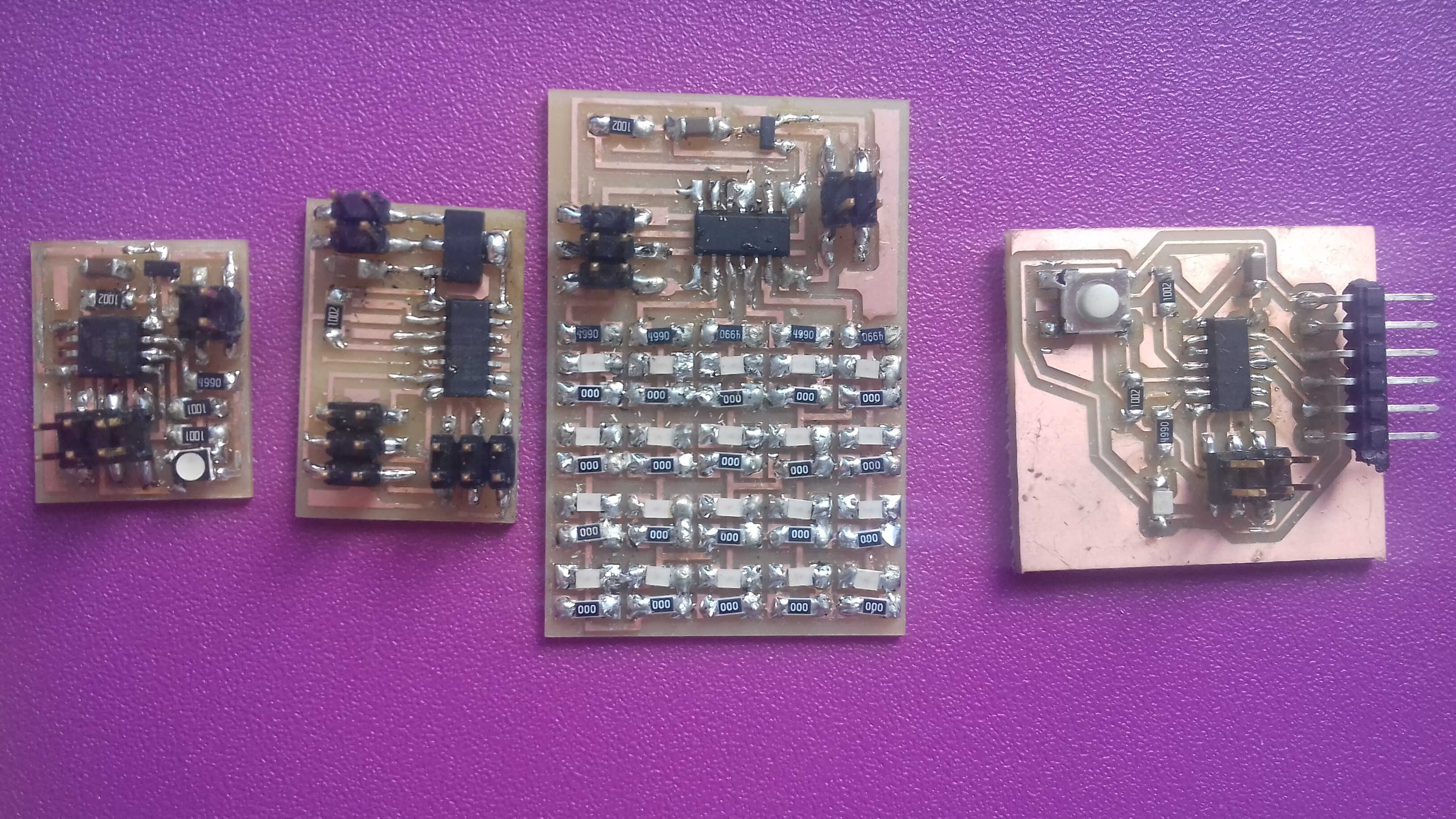
all boards
PWM -pulse width modulation
The first step of this week was to check the powering of the self-built board. As suspected all my troubles from last week emerged from an under-powering. Once the board powered with Thomas USB to FTDI cable, all worked smoothly. If the Arduino board can make exceptions and power the boards through the ISP, the FabISP can't. Once the board correctly powered my FabISP could be used as programmer.
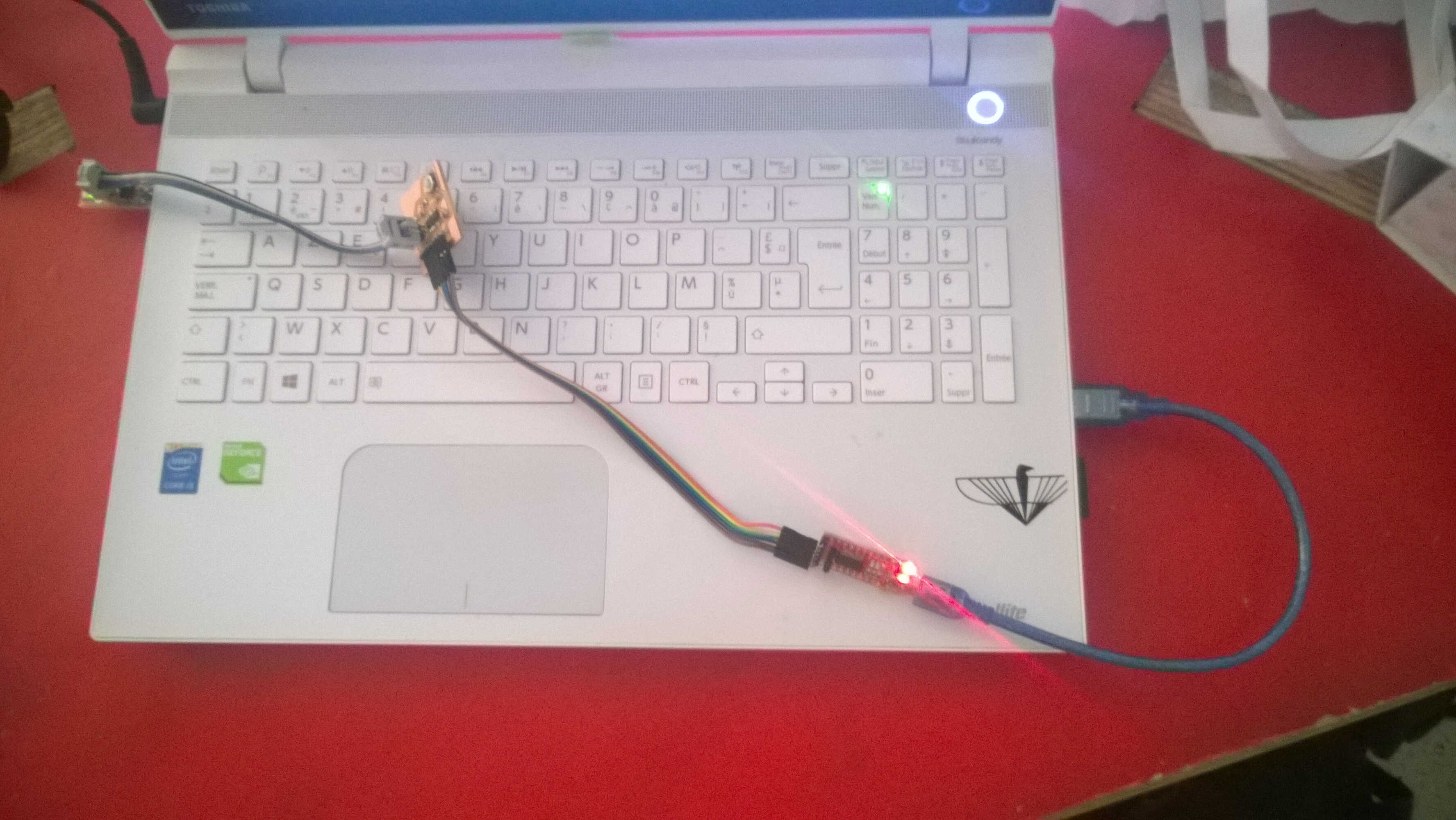
powering
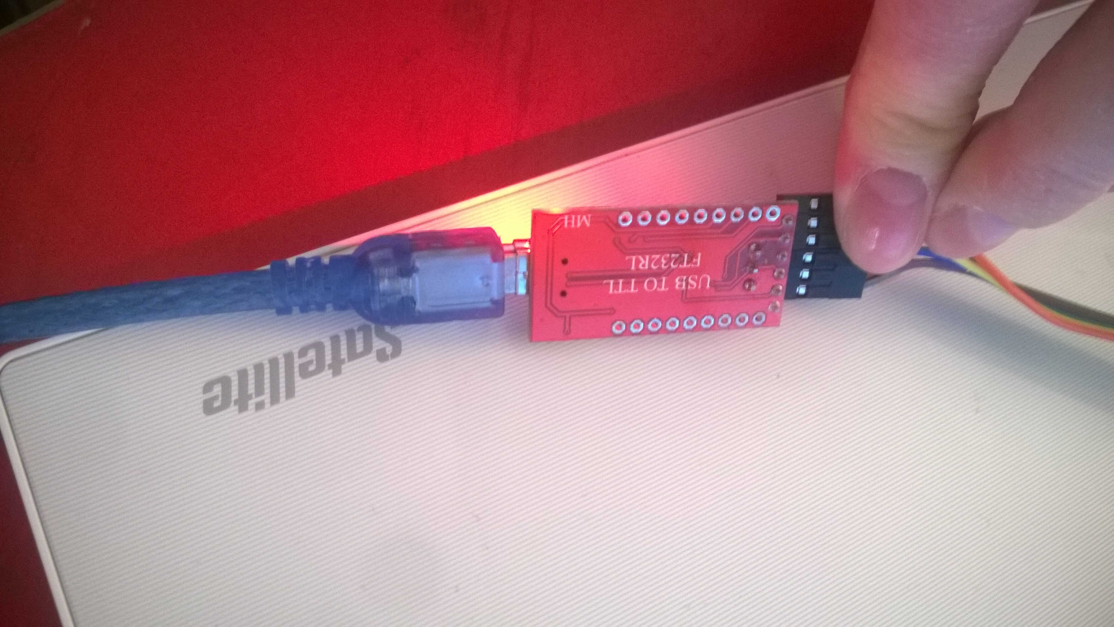
USA > FTDI cable
I programmed my board with the led and the button from embedded programming week for PMW. I tried several C sketches but only Neil worked.
int main(void)
{
    DDRA   |= (1 << PA7);                   // PWM output on PA7
    TCCR0A = (1 << COM0A1) | (1 << WGM00);  // phase correct PWM mode
    OCR0A  = 0x10;                          // initial PWM pulse width

    TCCR0A = (1 << CS01);   // clock source = CLK/8, start PWM

    while(1)
    {
        // change PWM pulse width every 2 seconds
        _delay_ms(2000);
        OCR0A  = 0x10;
        _delay_ms(2000);
        OCR0A  = 0x30;
        _delay_ms(2000);
        OCR0A  = 0x50;
        _delay_ms(2000);
        OCR0A  = 0xA0;
    }
}
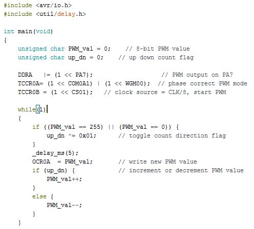
non-working continous PWM sketch
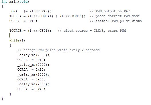
non-working discrete PWM sketch
| DDR | TCCR0 | COM0 | WGM00 | CS0 | OCR0 |
|---|---|---|---|---|---|
| Port Data direct register | Time counter control register | Compare output mode | Waveform generation mode | Clock selection | Output compare register |
I am still not sure to understand how the output comparing between ports works. I then loaded Neil's code.
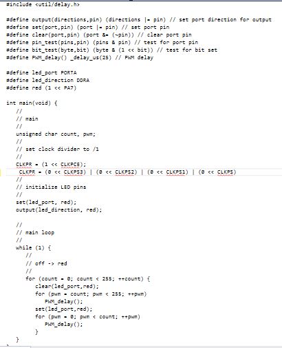
Neil's sketch
The two tests functions are not used in this script. We notice that Neil's code is longer than the 2 previous ones.
| CLKPR | CLKPCE | CLKPS |
|---|---|---|
| Clock prescaler register | Clock prescaler change enable | Clock prescale bits |
The PMW in Neil's sketch is based on the clock prescaler. In Neil's code all the clock prescale bits are set to 0 (the clock prescale is divided by 1). By changing those bits the modulation and the frequency change, I made a test with the clock prescale bits set to 1 0 1 0 - a reserved combination. The result is an asymetrical pulse.
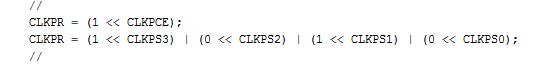
Clock bits change
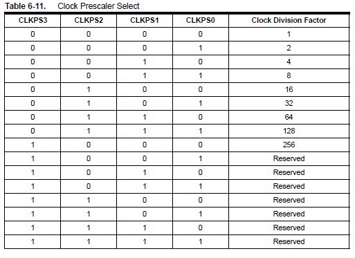
Clock bits
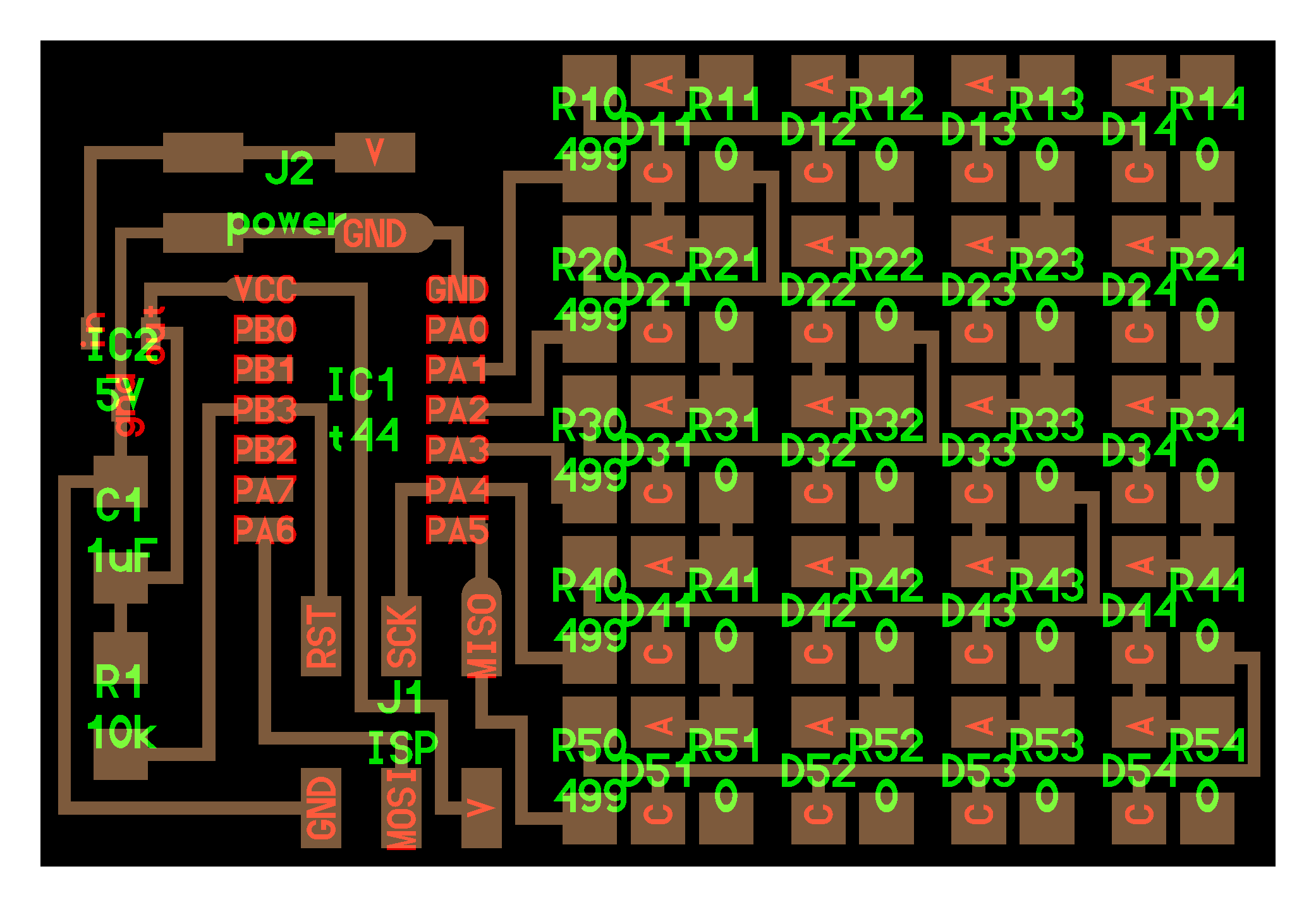
Led array: CharliePlexing
Multiplexing allows to control more device than they are of pins used. Here a nice example of 3D Charlieplexing:
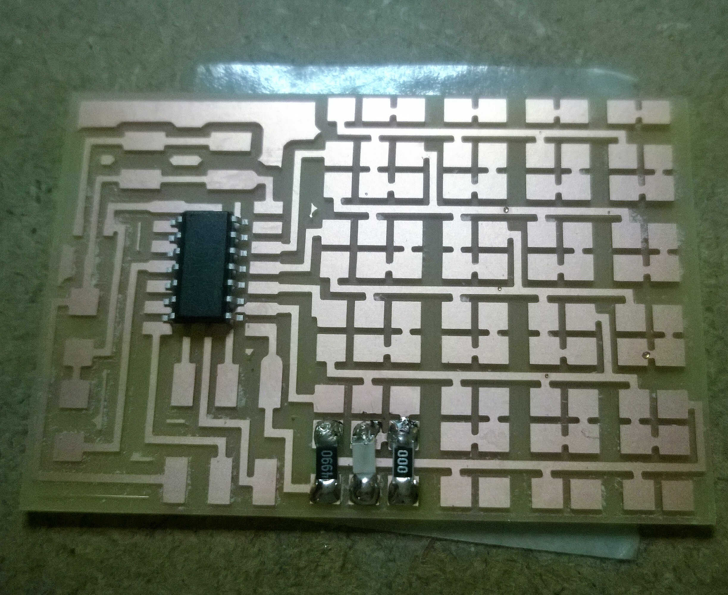
With Neil's board we are controlling 20 Leds with 5 pins. In fabmodules I had some doubts regarding the tool path so I changed the resolution to 1000 dpi, forgetting to check the dimensions. My board ended being over-sizedb>. I decided to use it anyway, the only problematic component was the Attiny; by merging traces, switching output pins and raising some pins of the microcontroller I soldered my board correctly.
size issue
left size fix
right size fix
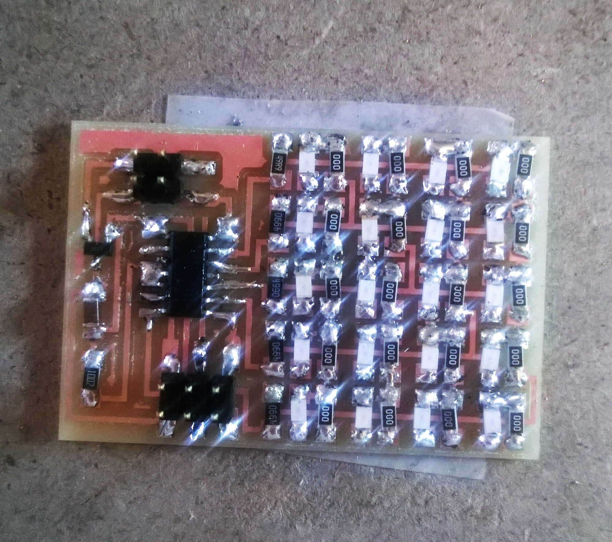
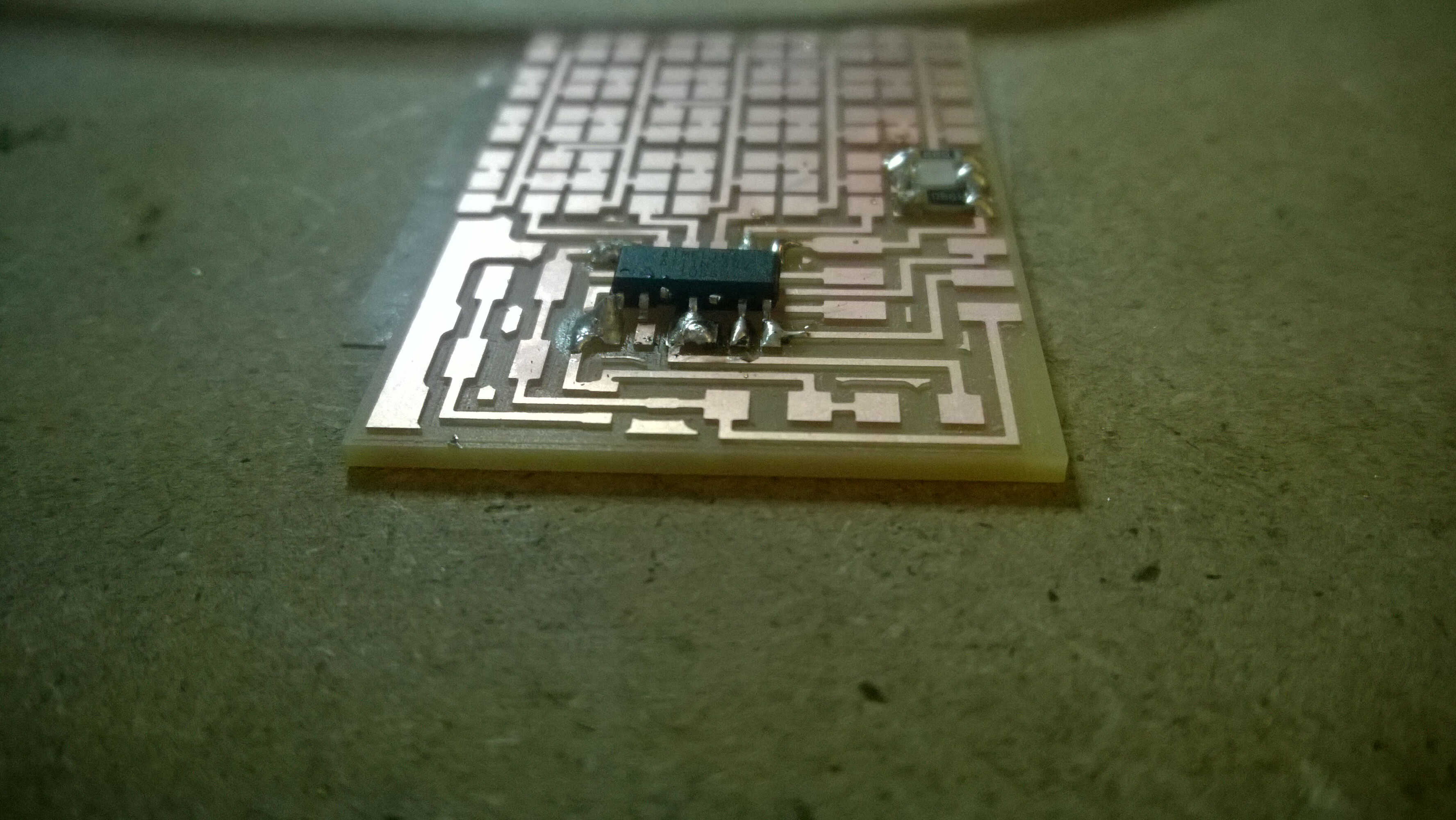
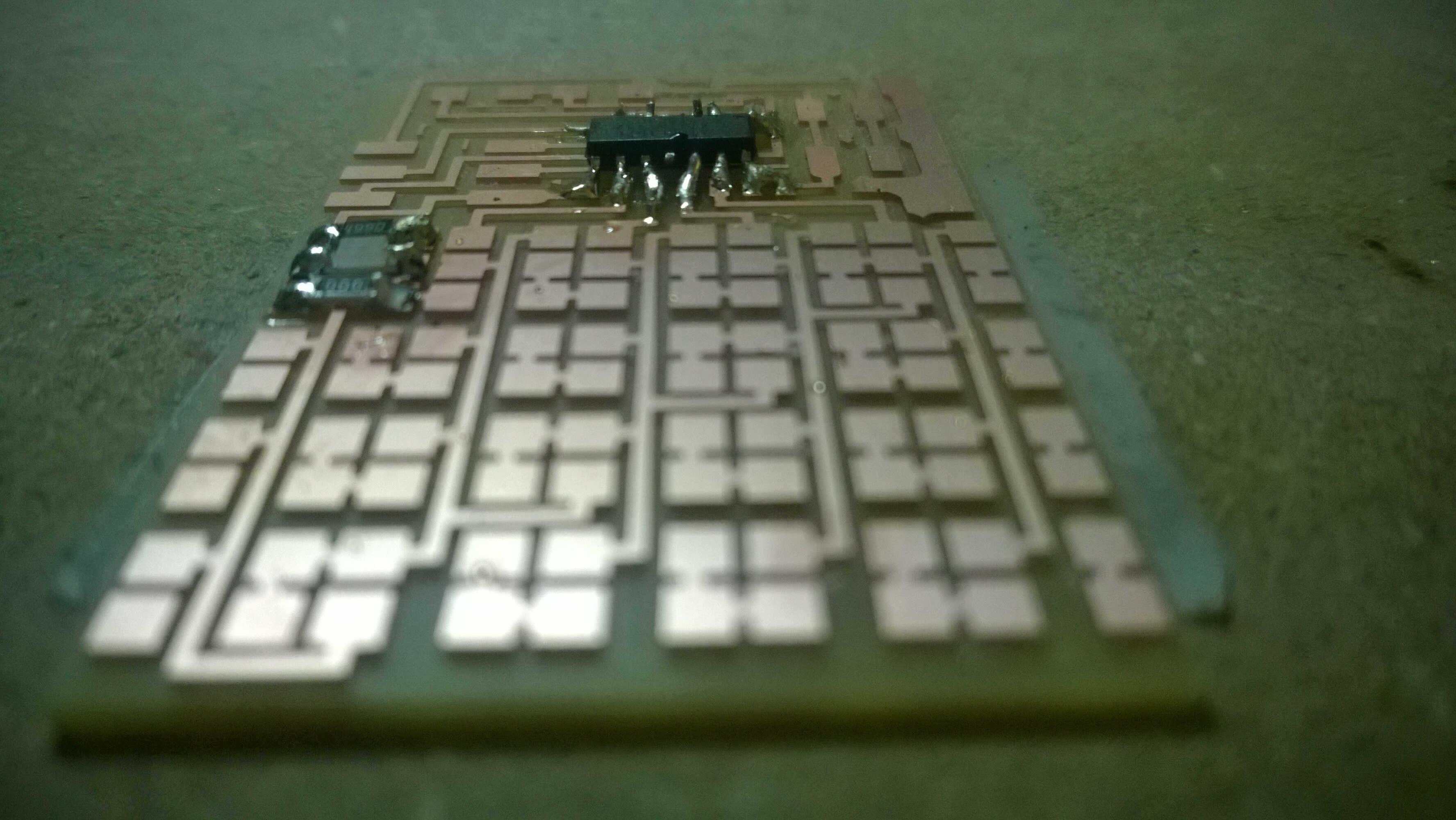
soldering done
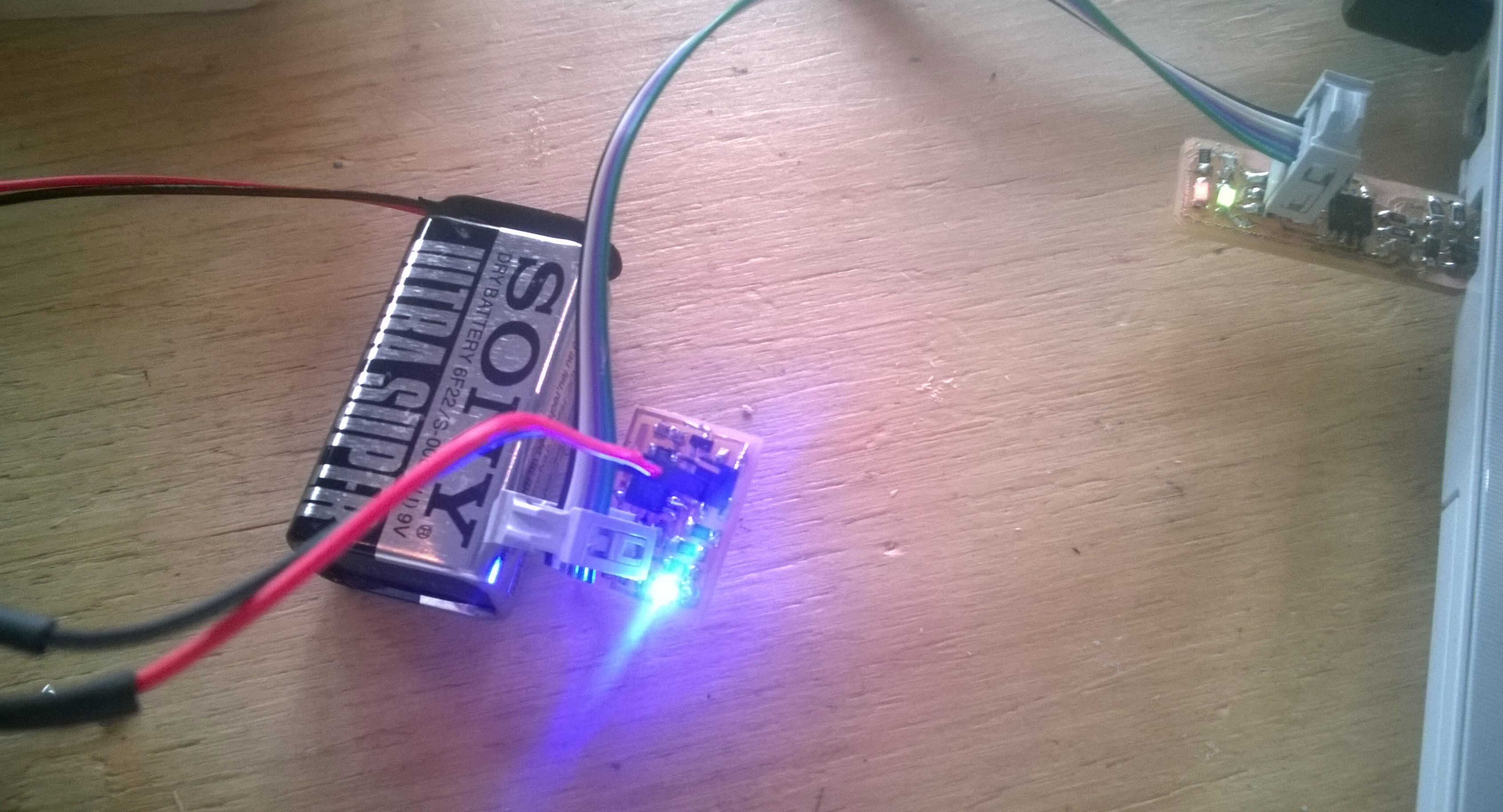
In order to power it I needed to connect it to a batery, as we didn't have female to female cables we built a battery to female cable.
To do so we took a 9V battery snapper and 2 male to female cables. We cut the male parts, stripped the cables, intertwinned the cable extremities with the ones of the battery snapper and soldered them together. Once done we protected the connection with heat shrink insulation.
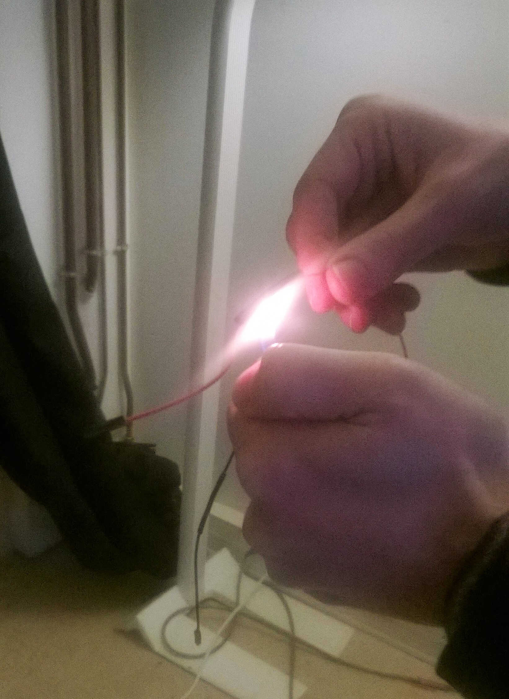
heat shrinking
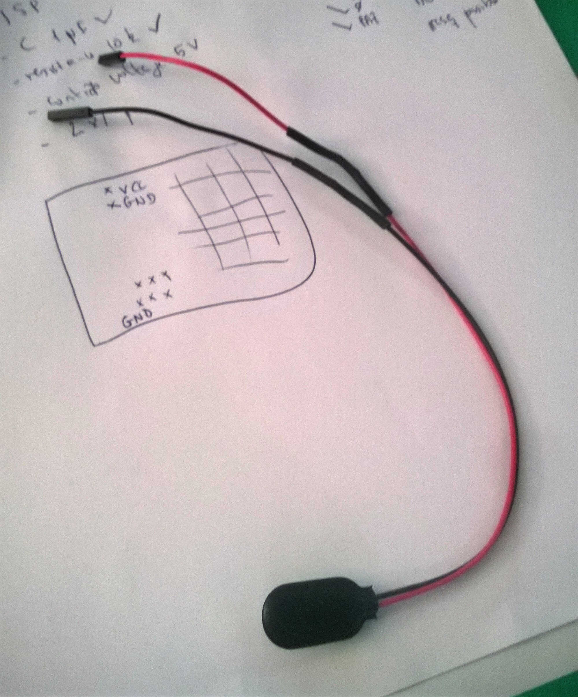
battery cable
The connection went smoothly.
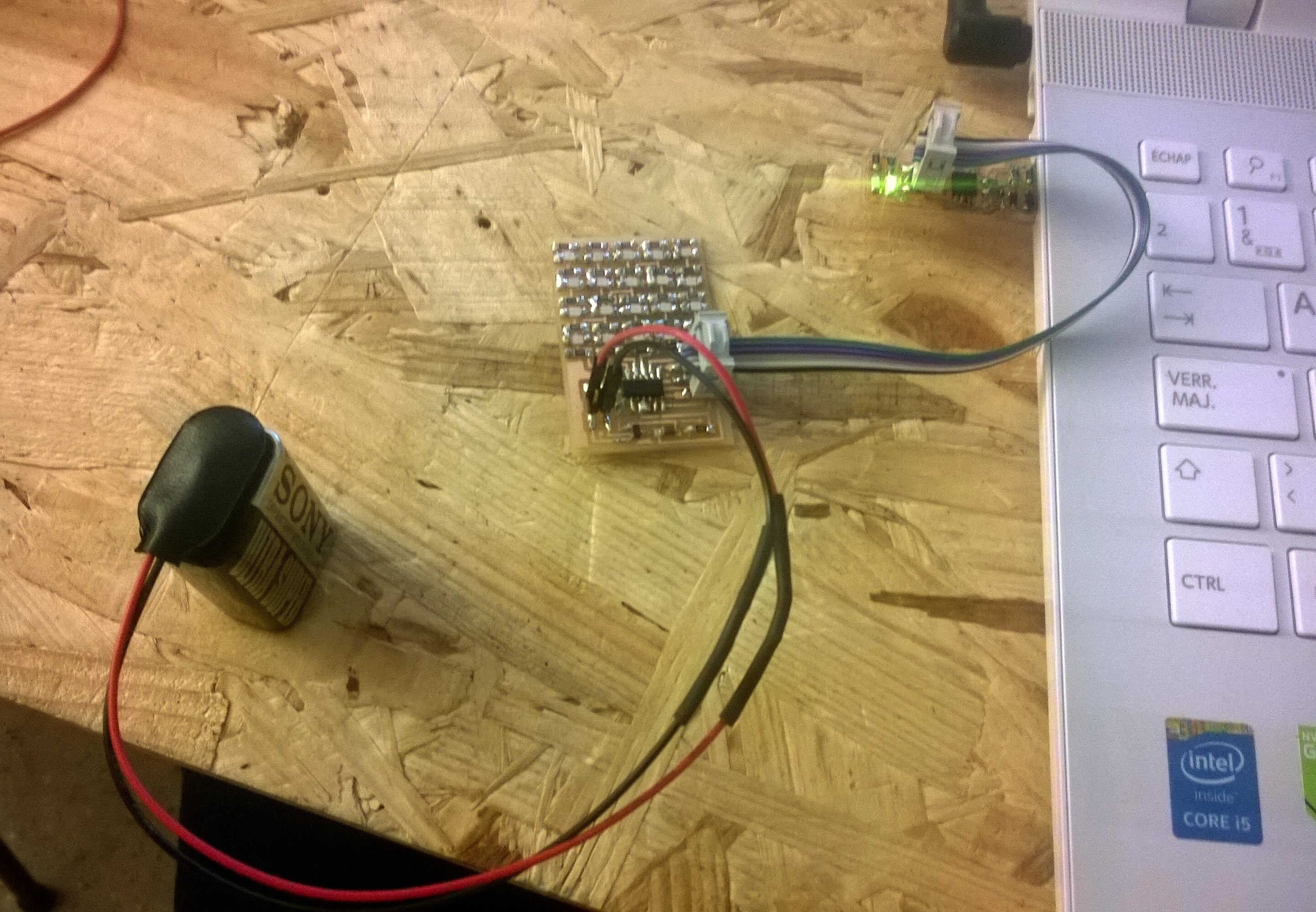
connection ok
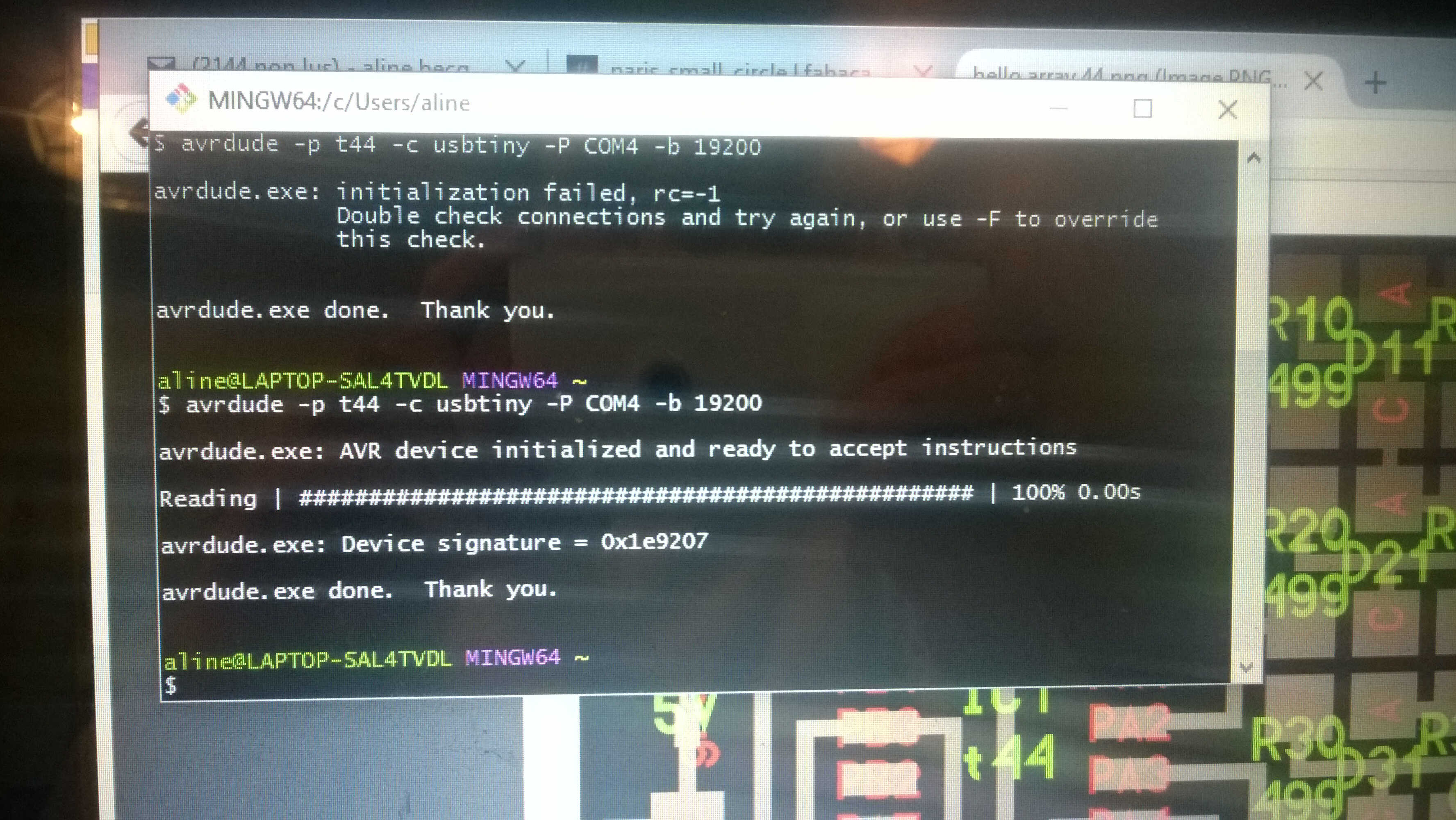
avrdude ok
At the first try not all the Led lit up. It took me some times to fix it mainly by resoldering. I noticed that packets of solder can turn to be insulating.
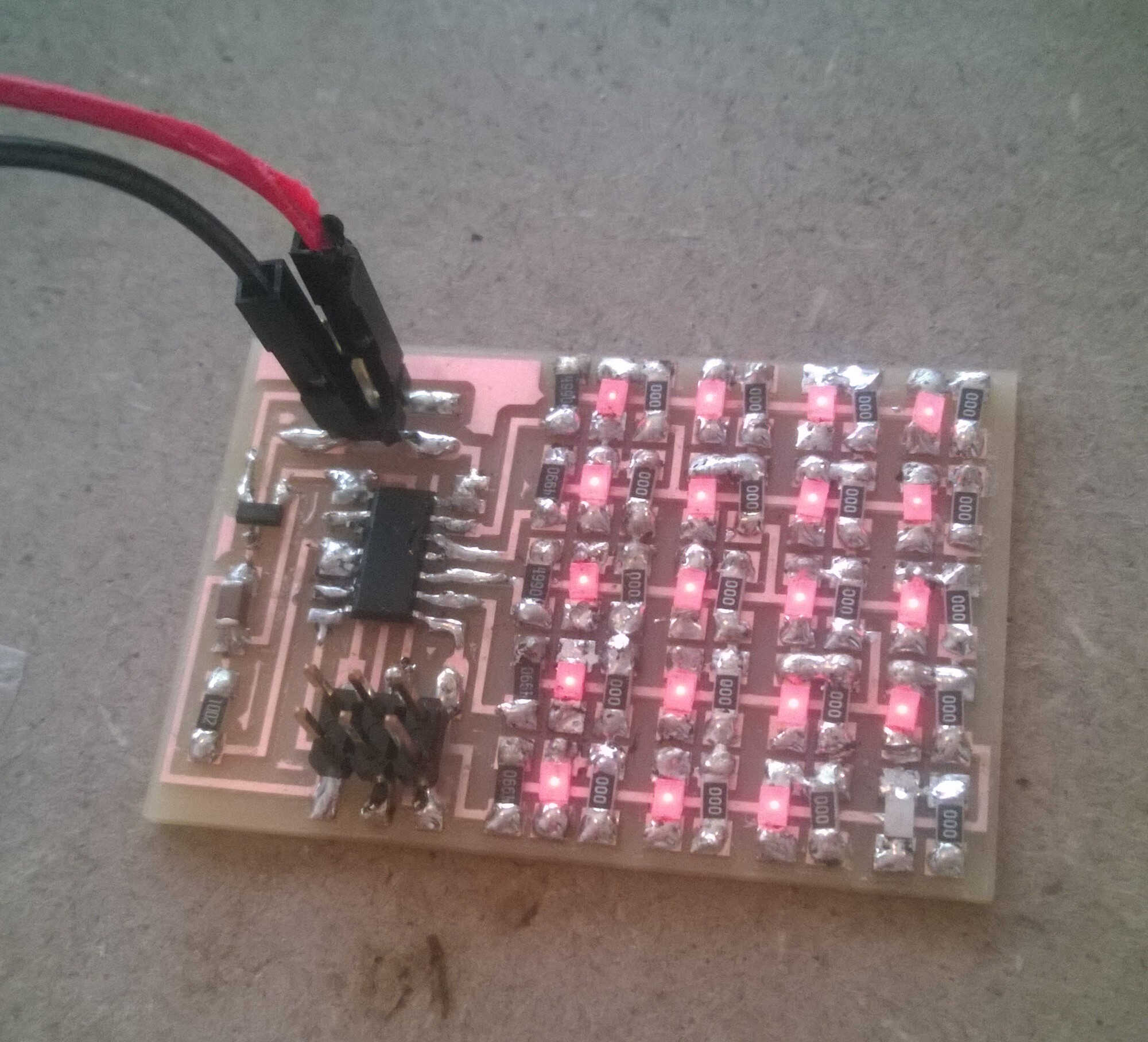
nearly there
I used Neil's code
#include <avr/io.h>
#include <util/delay.h>

#define output(directions,pin) (directions |= pin) // set port direction for output
#define input(directions,pin) (directions &= (~pin)) // set port direction for input
#define set(port,pin) (port |= pin) // set port pin
#define clear(port,pin) (port &= (~pin)) // clear port pin
#define pin_test(pins,pin) (pins & pin) // test for port pin
#define bit_test(byte,bit) (byte & (1 << bit)) // test for bit set

#define led_delay() _delay_ms(1) // LED delay

#define led_port PORTA
#define led_direction DDRA

#define A (1 << PA1) // row 1
#define B (1 << PA2) // row 2
#define C (1 << PA3) // row 3
#define D (1 << PA4) // row 4
#define E (1 << PA5) // row 5

void flash(uint8_t from, uint8_t to, uint8_t delay) {
   //
   // source from, sink to, flash
   //
   static uint8_t i;
   set(led_port,from);
   clear(led_port,to);
   output(led_direction,from);
   output(led_direction,to);
   for (i = 0; i < delay; ++i)
       led_delay();
   input(led_direction,from);
   input(led_direction,to);
   }

void led_cycle(uint8_t number, uint8_t delay) {
   //
   // cycle through LEDs
   //
   uint8_t i;
   for (i = 0; i < number; ++i) {
      flash(B,A,delay);
      flash(C,A,delay);
      flash(D,A,delay);
      flash(E,A,delay);
      flash(A,B,delay);
      flash(C,B,delay);
      flash(D,B,delay);
      flash(E,B,delay);
      flash(A,C,delay);
      flash(B,C,delay);
      flash(D,C,delay);
      flash(E,C,delay);
      flash(A,D,delay);
      flash(B,D,delay);
      flash(C,D,delay);
      flash(E,D,delay);
      flash(A,E,delay);
      flash(B,E,delay);
      flash(C,E,delay);
      flash(D,E,delay);
      }
   }

int main(void) {
   //
   // set clock divider to /1
   //
   CLKPR = (1 << CLKPCE);
   CLKPR = (0 << CLKPS3) | (0 << CLKPS2) | (0 << CLKPS1) | (0 << CLKPS0);
   //
   // main loop
   //
   while (1) {
      led_cycle(1,100);
      led_cycle(3,20);
      led_cycle(100,1);
      }
   }
I made some tests commenting some lines to better visualize the led controlled by the pins. In the interface week I wanted to build an interface showing the wiring of the board but got caught by the time.
Rgb led
I also build Neil's RGB Led board .
Rgb board powered
#include <avr/io.h>
#include <util/delay.h>

#define output(directions,pin) (directions |= pin) // set port direction for output
#define set(port,pin) (port |= pin) // set port pin
#define clear(port,pin) (port &= (~pin)) // clear port pin
#define pin_test(pins,pin) (pins & pin) // test for port pin
#define bit_test(byte,bit) (byte & (1 << bit)) // test for bit set
#define PWM_delay() _delay_us(25) // PWM delay

#define led_port PORTB
#define led_direction DDRB
#define red (1 << PB1)
#define green (1 << PB0)
#define blue (1 << PB2)

int main(void) {
   //
   // main
   //
   unsigned char count, pwm;
   //
   // set clock divider to /1
   //
   CLKPR = (1 << CLKPCE);
   CLKPR = (0 << CLKPS3) | (0 << CLKPS2) | (0 << CLKPS1) | (0 << CLKPS0);
   //
   // initialize LED pins
   //
   set(led_port, red);
   output(led_direction, red);
   set(led_port, green);
   output(led_direction, green);
   set(led_port, blue);
   output(led_direction, blue);
   //
   // main loop
   //
   while (1) {
      //
      // off -> red
      //
      for (count = 0; count < 255; ++count) {
         clear(led_port,red);
         for (pwm = count; pwm < 255; ++pwm)
            PWM_delay();
         set(led_port,red);
         for (pwm = 0; pwm < count; ++pwm)
            PWM_delay();
         }
      //
      // red -> green
      //
      for (count = 0; count < 255; ++count) {
         set(led_port,red);
         clear(led_port,green);
         for (pwm = count; pwm < 255; ++pwm)
            PWM_delay();
         clear(led_port,red);
         set(led_port,green);
         for (pwm = 0; pwm < count; ++pwm)
            PWM_delay();
         }
      //
      // green -> blue
      //
      for (count = 0; count < 255; ++count) {
         set(led_port,green);
         clear(led_port,blue);
         for (pwm = count; pwm < 255; ++pwm)
            PWM_delay();
         clear(led_port,green);
         set(led_port,blue);
         for (pwm = 0; pwm < count; ++pwm)
            PWM_delay();
         }
      //
      // blue -> on
      //
      for (count = 0; count < 255; ++count) {
         set(led_port,blue);
         clear(led_port,green);
         clear(led_port,red);
         for (pwm = count; pwm < 255; ++pwm)
            PWM_delay();
         set(led_port,blue);
         set(led_port,green);
         set(led_port,red);
         for (pwm = 0; pwm < count; ++pwm)
            PWM_delay();
         }

      //
      // on -> off
      //
      for (count = 0; count < 255; ++count) {
         set(led_port,blue);
         set(led_port,green);
         set(led_port,red);
         for (pwm = count; pwm < 255; ++pwm)
            PWM_delay();
         clear(led_port,blue);
         clear(led_port,green);
         clear(led_port,red);
         for (pwm = 0; pwm < count; ++pwm)
            PWM_delay();
         }
      }
   }
Servo board
Finally I wanted to build Neil's servo board but never got it to work. I fixed a short circuit caused by too close traces but it looks like the regulator had some disfunctions.
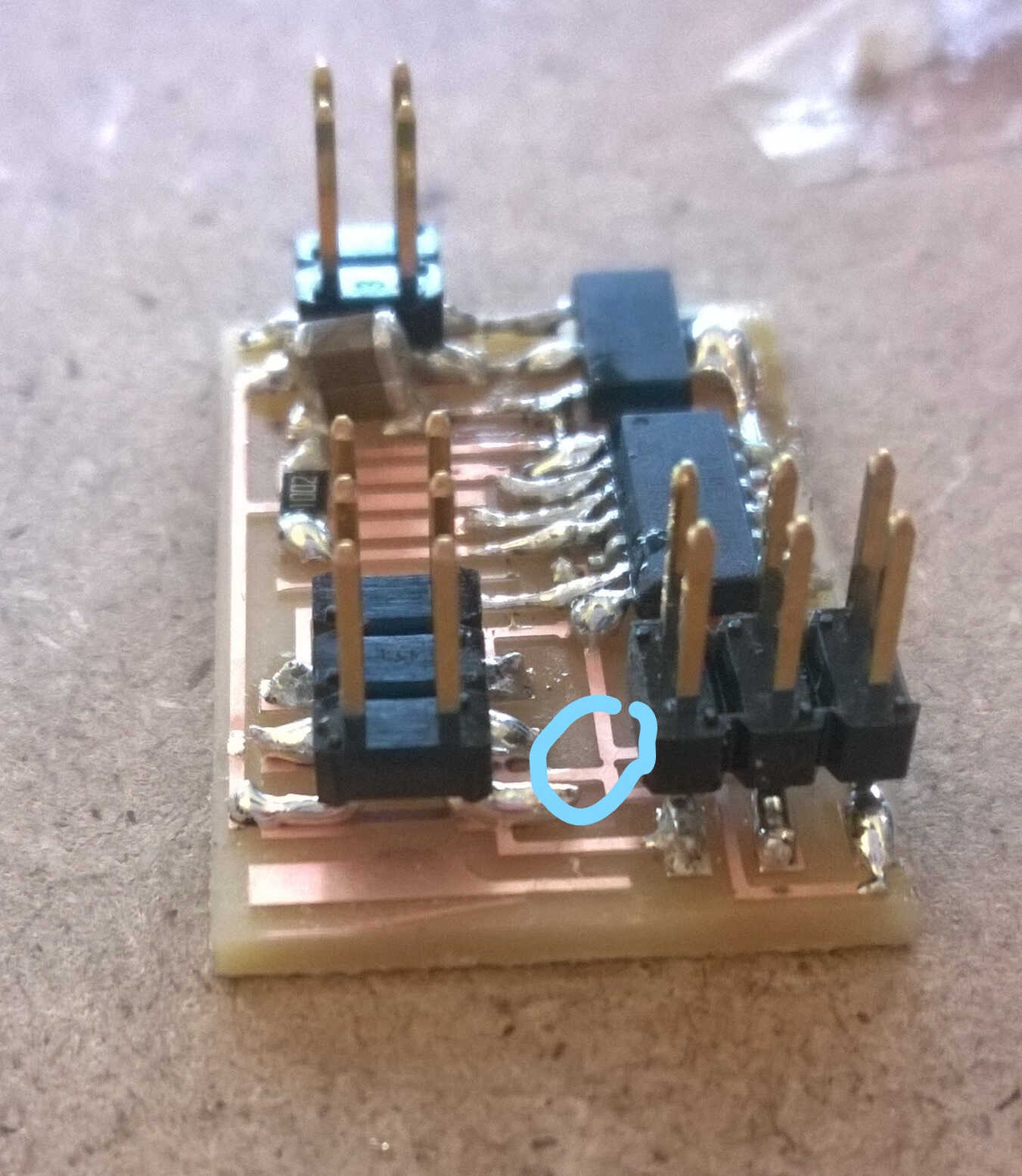
short-circuit trace
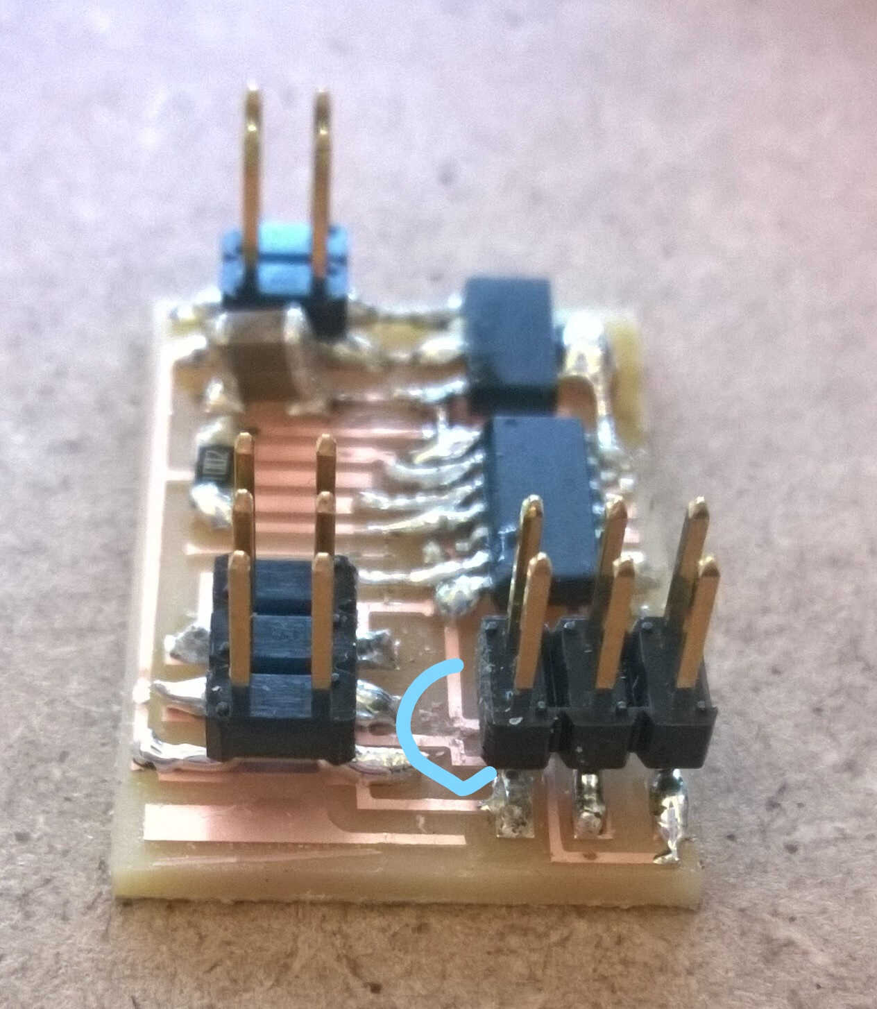
cutter-fix
Traffic light
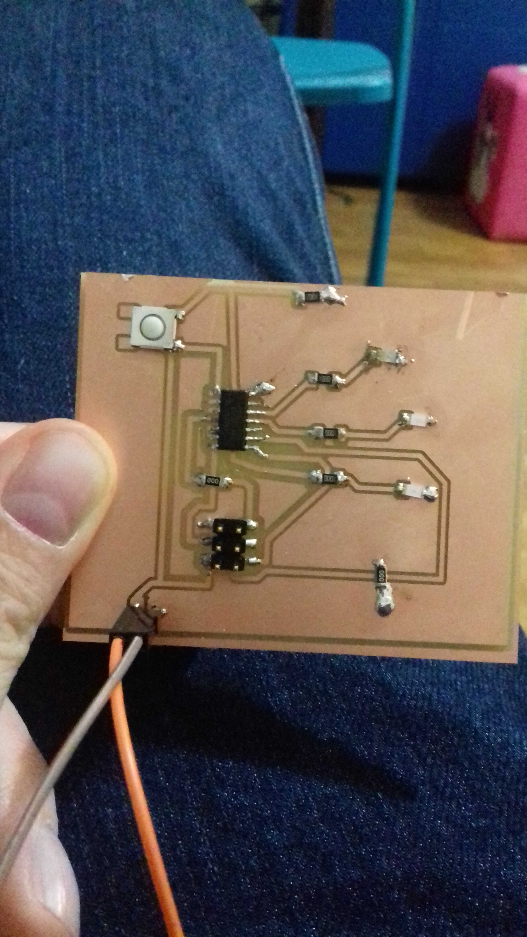
Thomas told me this might not be enough for this assignement so I created a really simple traffic light board.
- An Attiny44
- 3 leds (red, yellow, green) each protected with a resistor.
- An ISCP connector
- A power/VCC connector
- A button to optionnally control the led with a high resistor to avoid short-circuit
I build a ground plane but ended up with two separate ones that I linked with a 0 ohm resistor. I also used a 0 ohm resistor to cross a wire.

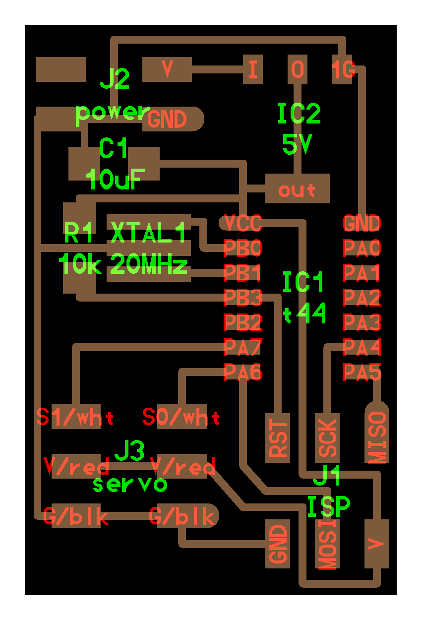
schematic

board
soldered
To design this board I first added the components, then the wire connections that I named accordingly.
I chose 3 free analog pins for the led.
I checked the ERC then switched to the board view.
In the board view I arranged the components so the traces get as untangled as possible.
I used the autorouter in easy mode to get the traces, the autorouter takes into account the rules defined in DRC
If I couldn't reach 100% of success of the autorouter I evaluated the result. I looked at what couldn't be joined and displaced this component to improve the result.
When I noticed that the remaining percentage corresponded to ground not connected and ground that could be connected with 0 ohm resistor I accepted the autorouter result.
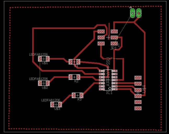
I build a ground plane by drawing a polygon from the top layer and naming it as ground (GND).
I used the rastnest tool to get the plane to be optimized
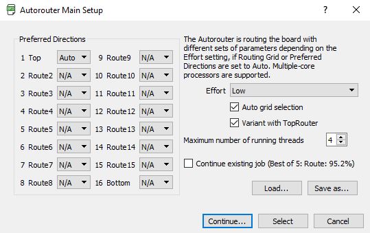
autorouter
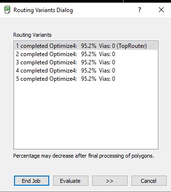
autorouter result
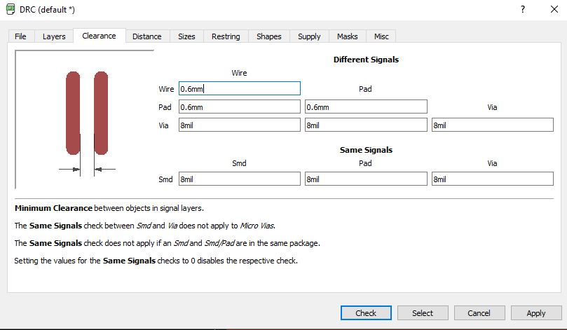
DRC rules
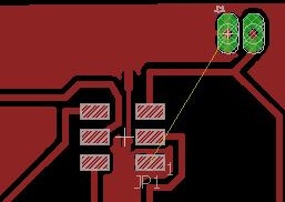
When I noticed that the remaining percentage corresponded to ground not connected and ground that could be connected with 0 ohm resistor and one crossing of trace with a 0 resistor. I accepted the autorouter result. The unconnected grounds can be seen at the remaining yellow lines between grounds on the board view. Due to DRC 2 grounds which could be connect weren't. I added a thin line to bridge the two.
I build a ground plane by drawing a polygon from the top layer and naming it as ground (GND).
I used the rastnest tool to get the plane to be optimized.
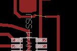
crossing
thin line
polygone in dash
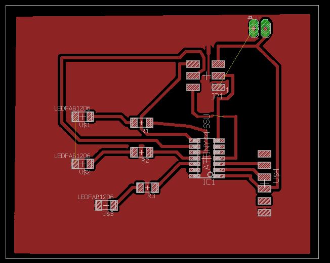
after rastnest
Here the code:
      void setup() {
  pinMode(A1, OUTPUT);
  pinMode(A2, OUTPUT);
  pinMode(A3, OUTPUT);
  //pinMode(BUTTONPIN, INPUT);
}

/*
  Each time we loop through the program we should check the state of our pushbutton, then
  fade the lights.
*/
void loop() {
 analogWrite(A1, 255);
 delay(2000);
 analogWrite(A1, 0);
 delay(2000);
 analogWrite(A2, 255);
 delay(2000);
  analogWrite(A2, 0);
 delay(2000);
 analogWrite(A3, 255);
 delay(2000);
 analogWrite(A3, 0);
 delay(2000);
}
Source file to load here