Abstract
This week was about learning to design an input board and to visualize the incoming signal
Some of the question raised were:
- What is the simplest way to input a data?
- What are the difference between analog and digital inputs?
- What are the interface from visualizing inputs?
I mainly used 1 workflow:
Eagle > Arduino/Git
My biggest achievement:
My biggest struggle: Still soldering
Missing material
| 22 pF capacitors | 2 pins 16 MHz crystal |
Chronology
| Thursday | Friday | Monday | Tuesday | |
|---|---|---|---|---|
| Demo | Personal design | Documentation | Temperature board | |
| Personal design | Milling/soldering sonar board | Arduino input test | FTDI tests | |
| Personal board milling | Satchakit board modifications/milling |
Setup
| Softwares | Fonction |
|---|---|
Skills acquired
Asssesment validation
Thomas and Roman advised us to build a satchakit and design input boards to be added to it, hence without ATtiny45. Also they advised me to look at step response.
Polygonal board
I followed their advice and tried to build a step respnse board that could be added to molding/casting week output. That being a basic polygonal touch pad with only 2 connectors, a surface and a 1 MOhms resistance. I created an Eagle schematics with a resistance and a 2 holes connector. Roman advised me to inactivate all Eagle libraries except the fab one and to download Sparkfun libraries. I chose a connector from Sparkfun connector, one with long pads as Roman advised -this should have given me more space to solder. I wired the resistance to one of the holes. I probably should have wored the second hole to the other part of the resistance.
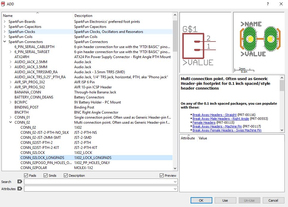
Sparkfun connector
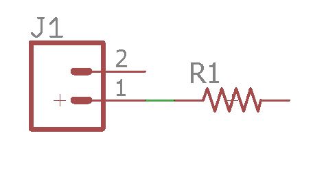
schematic
extracting the polygon touchpad
Then I exported it as .dxf and imported it in Eagle as .dxf in the top layer. I then designed the dimension as an offset of the pad, rotated th resistance, routed it to the pads and wired the resistance to the pad and the pad to the output pin. I exported the traces and the outlines as image as usual but I forgot to check the DRC.
Source file to load here
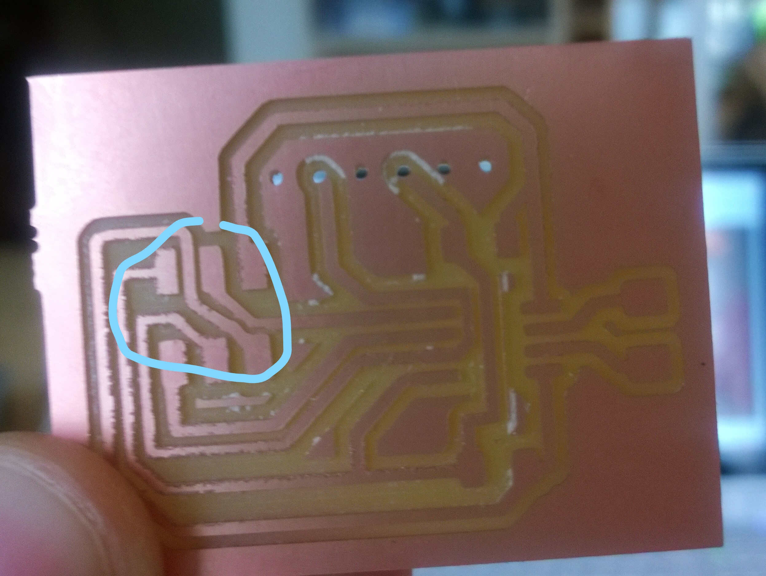
I milled it and soldered it. While soldering it I noticed an issue with the pads connector. The hole was not where it was supposed to be. I decided to circumvent this by soldering this connector at another place.
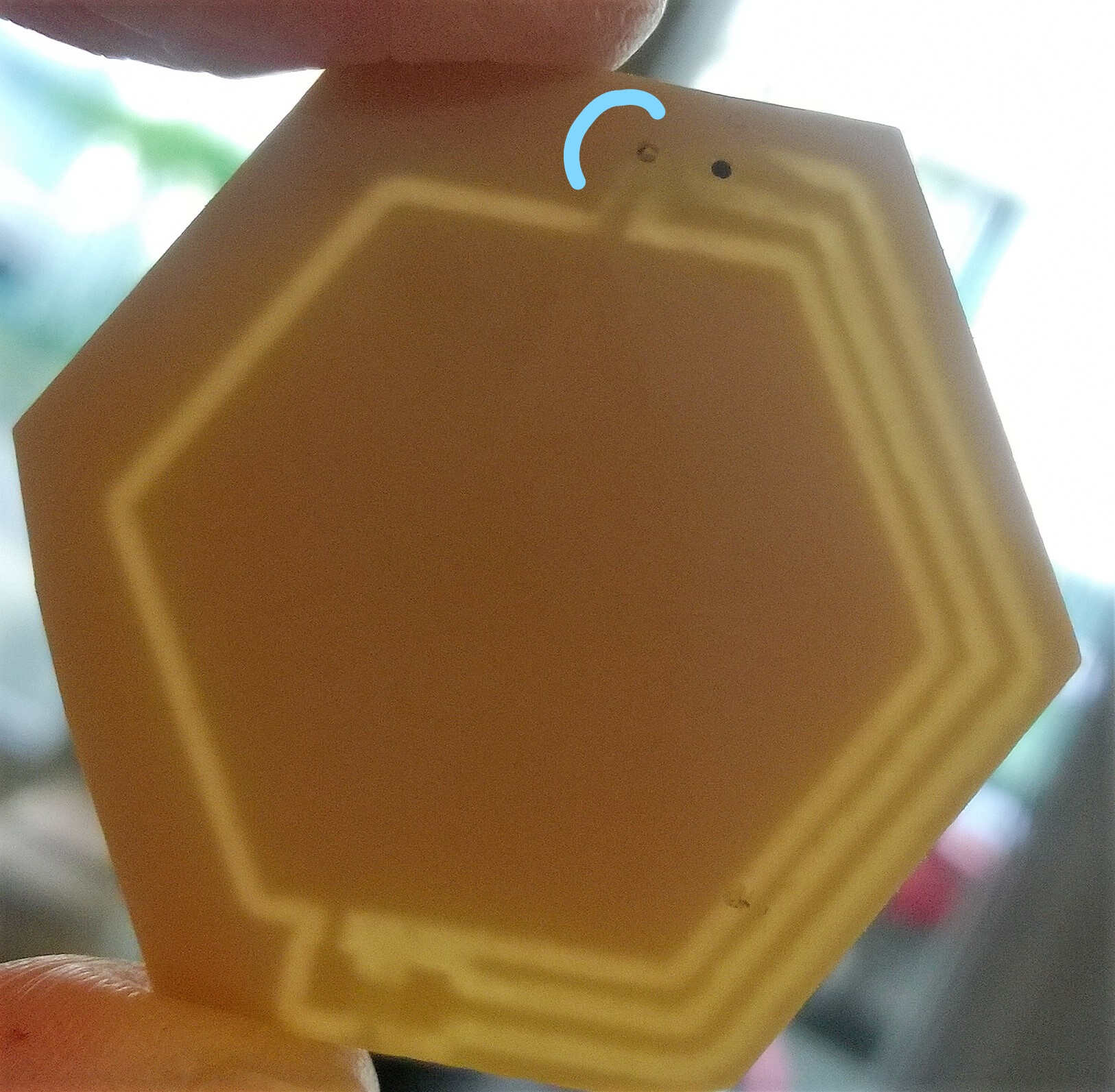
misplaced hole
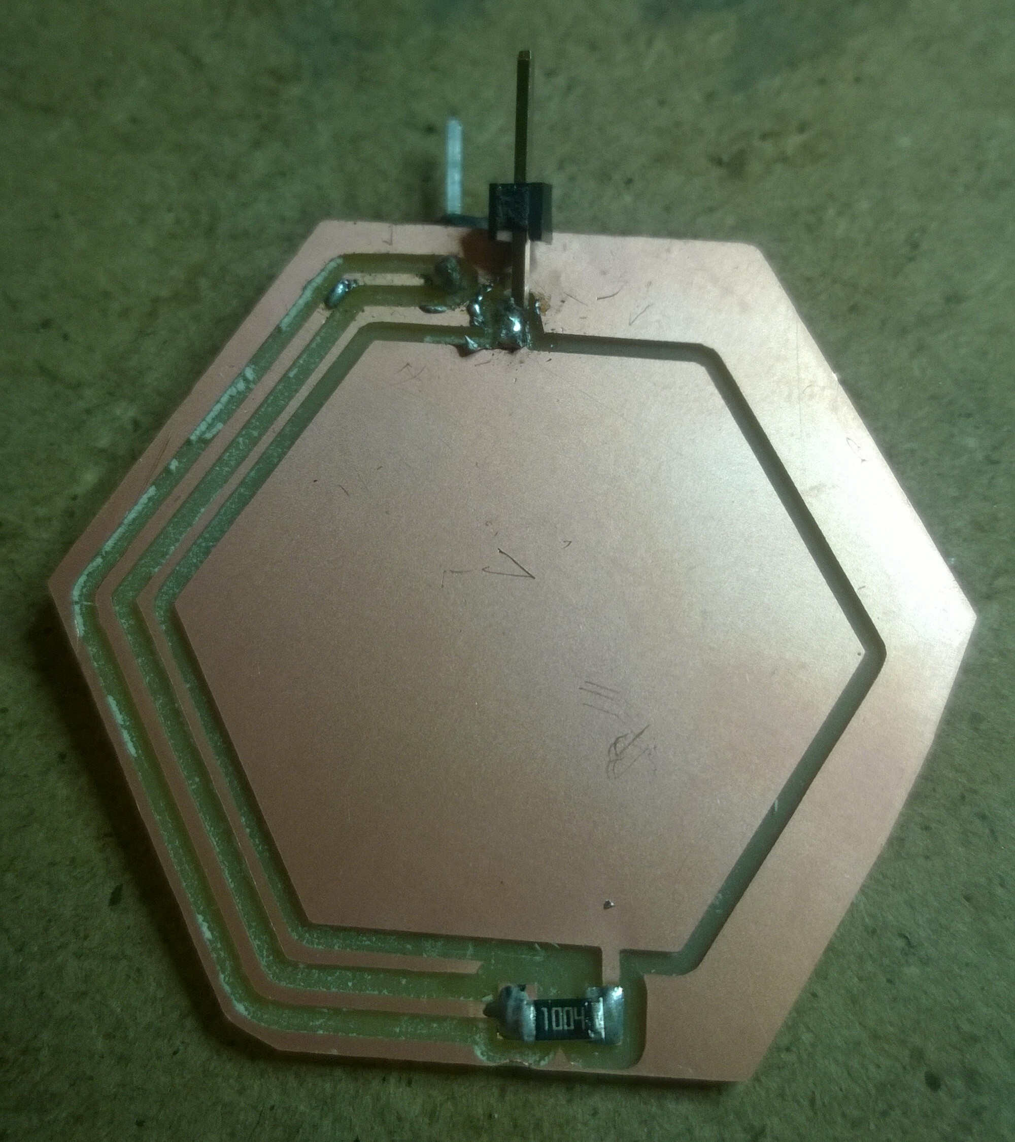
soldering fix
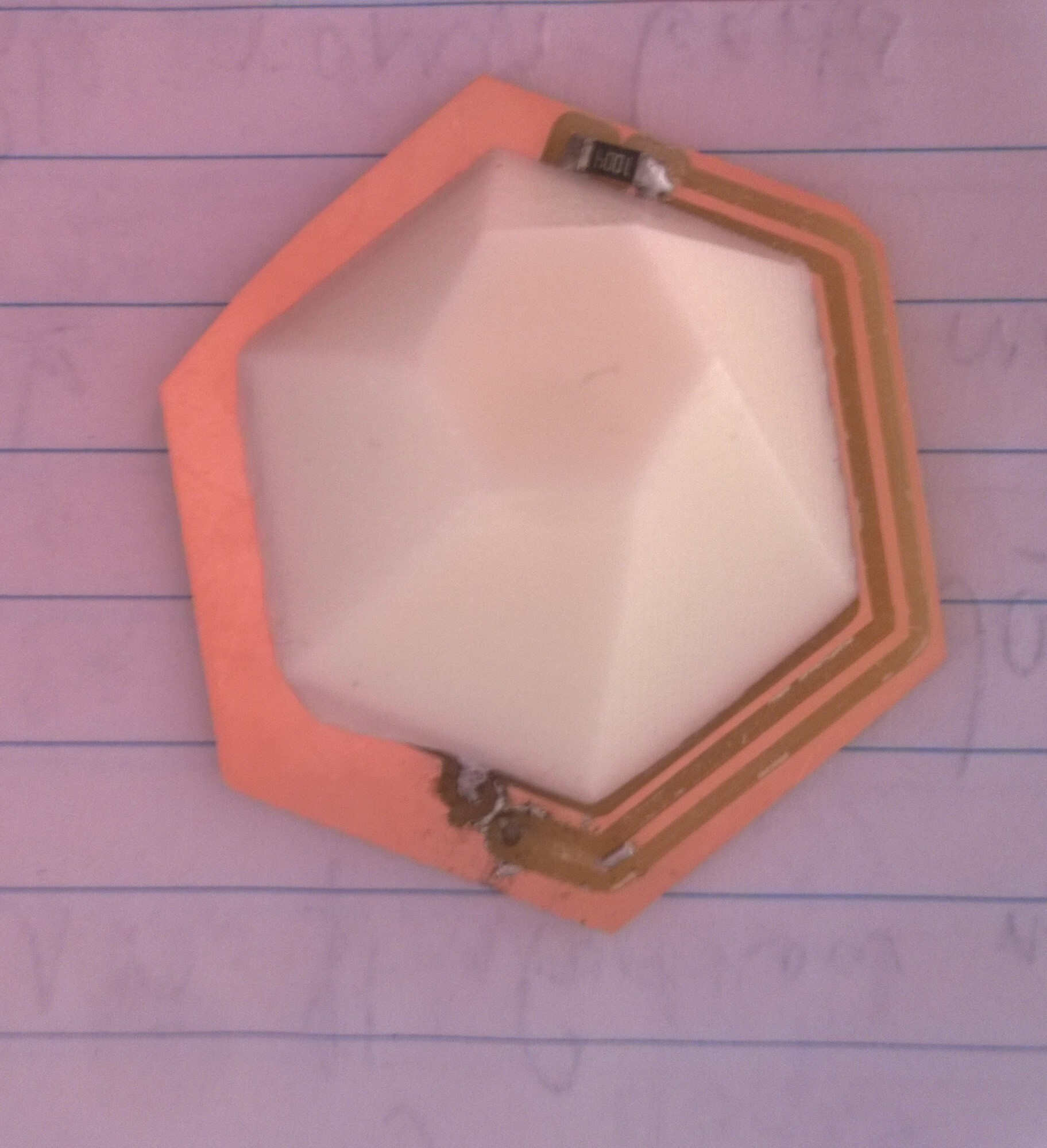
molding result as activator
The soldering is quite dirty as I tried different configurations.
Satchakit
In order to connect and control the input board I first wanted to reproduce a satchakit then to design my own but due to soldering issue I had no time for the second step.
The satchakit is a former Fabacademy project under the CC BY-NC-SA 4.0 licence, its authors are Daniele Ingrassia and Engineering Ingegneria Informatica. I slightly modified the traces to adapt the 2 pin crytal 20MHz we have at the location of the 16MHz one.

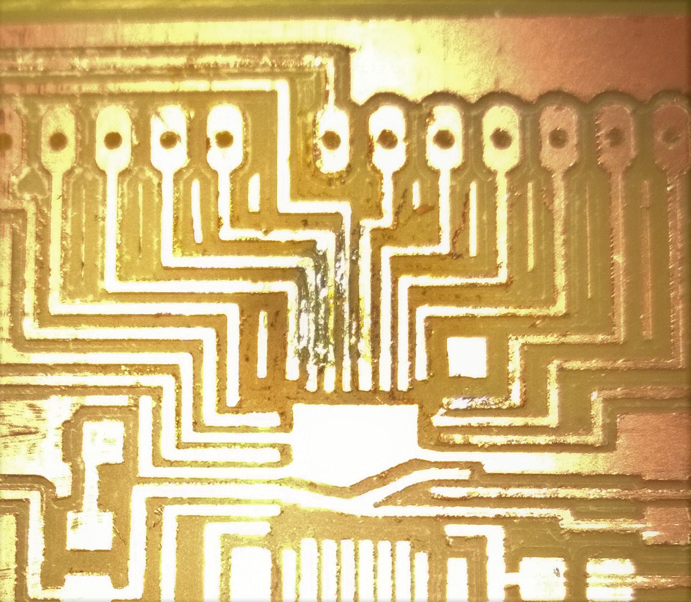
Roman version of Satchakit traces

my version
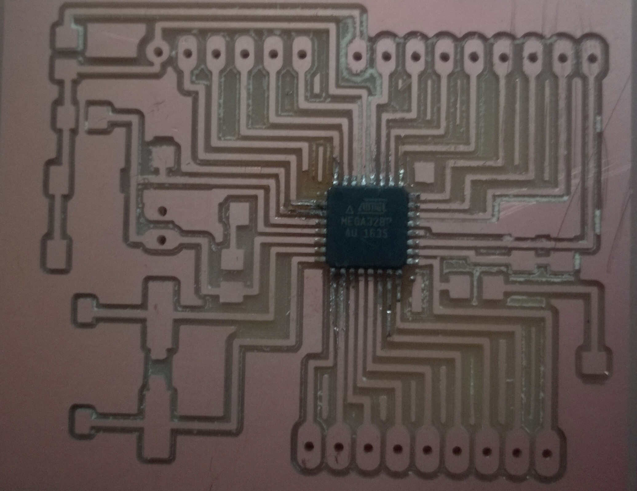
The milling took around half an hour and the milled Satchaboard came out a bit rough, this might be caused by an ageing bit or slight displacement during the milling. But all traces were well separated, only the end of one trace was missing. This could be fixed with solder. Yassine milled a couple of Satchakits and told me than half of them were defective.
rough traces -and missing bit
I gathered all the components needed for the board (minus a 22pF capacitor) and tried to solder the ATMega. I asked Thomas for help as I am not yet familiar with the new soldering station and the new solder/flux couple. He told me to brush to pads and the traces with flux, then I deposited a drop of solder on my soldreing iron tip and applied it on 4 pads with one move. This deposited solder in the interstices and I couldn't get them out -nor with desoldering braid nor with help on the hot air gun.
new solder -with flux- and flux
flux locked in interstices
Thomas suggested this might be due to the board roughness, so he milled a new one. I tried to mill the old way but got pads soldered together. I find it harder to use the desolder braid with a fine tip. Thomas succeeded in separting the solder by melting it again and by spreading it along the traces but also ordered soldering paste.
Thomas mastering the solder
Arduino
Due to the soldering issues, I will start playing with my board with the help of an Arduino. I connected the pins of my step response board to my Arduino following Arduino's example sketch TouchSensorLamp. I remembered this exercice from Arduino's project book. And this seem similar to what a step response code is doing. It uses the CapacitiveSensor library . This library mainly helps with sampling and calibration. It also gives guideline for the resistor choice and underlines the fact that the circuit needs to be grounded to show good repeatability.

resistance value
I ran it, then realized that when plugging the wires the traces got pulled off.
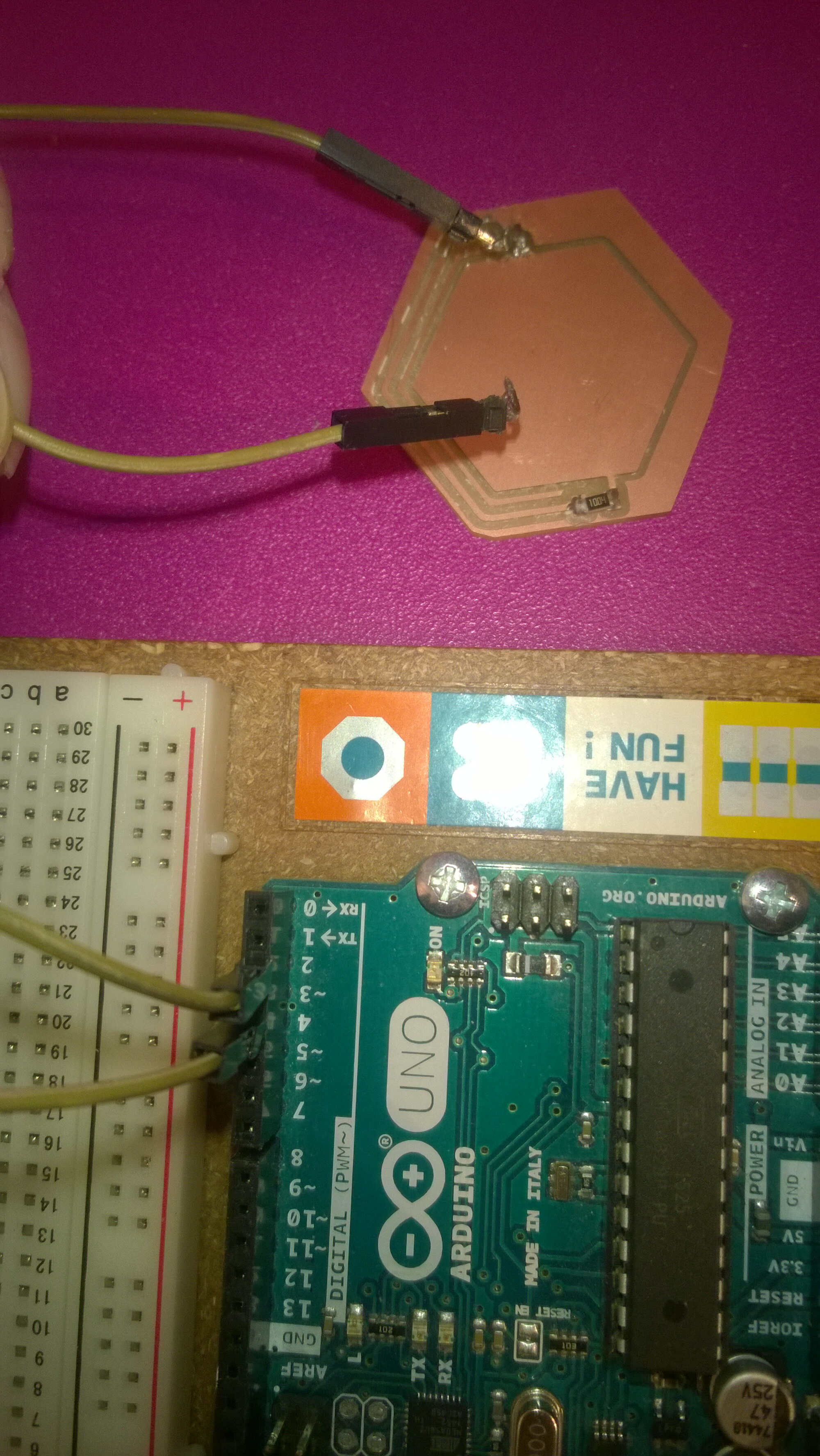
traces gone off
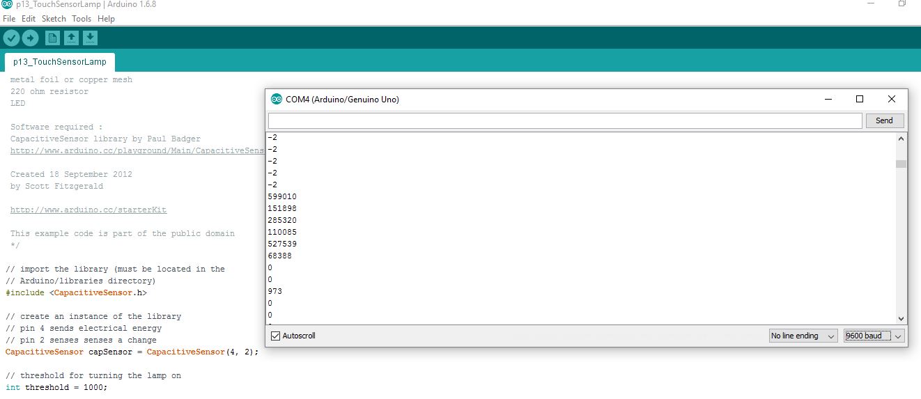
serial monitor
          #include <CapacitiveSensor.h>

// create an instance of the library
// pin 4 sends electrical energy
// pin 2 senses senses a change
CapacitiveSensor capSensor = CapacitiveSensor(4, 2);

// threshold for turning the lamp on
int threshold = 1000;

// pin the LED is connected to
const int ledPin = 12;


void setup() {
  // open a serial connection
  Serial.begin(9600);
  // set the LED pin as an output
  pinMode(ledPin, OUTPUT);
}

void loop() {
  // store the value reported by the sensor in a variable
  long sensorValue = capSensor.capacitiveSensor(30);

  // print out the sensor value
  Serial.println(sensorValue);

  // if the value is greater than the threshold
  if (sensorValue > threshold) {
    // turn the LED on
    digitalWrite(ledPin, HIGH);
  }
  // if it's lower than the threshold
  else {
    // turn the LED off
    digitalWrite(ledPin, LOW);
  }

  delay(10);
}
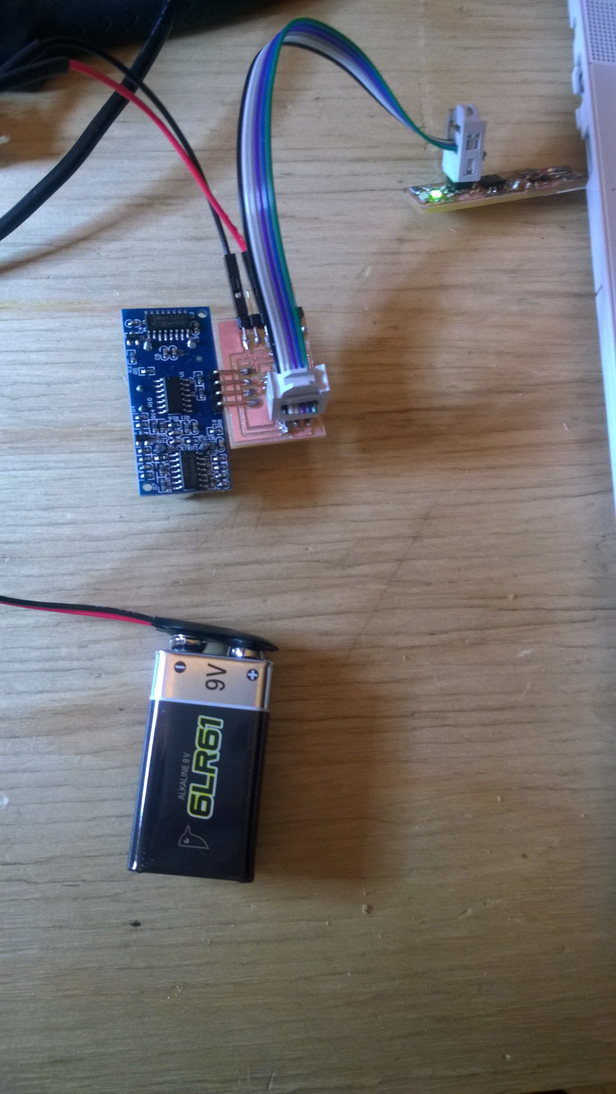
A bit panicked by the outputs of the step response boards and the fact that I didn't use a ATTiny 45, I decided to reproduce one of Neil's and to improve it later on. I picked the sonar one because we had several at WoMa. It is quite simple, only requires pins, a ATTiny 45, a capacitor and a resistance. I milled it and soldered it. At first I had short circuit caused by the capacitor solder. I resoldered it and the short-circuit was gone. I could power it with a 9V battery but couldn't communicate with it -maybe the voltage was too high-. That wasn't it I powered it with 5V pin of the Arduino and the result was the same. I checked all the connexions though. One thing stroke me however i connect the ribbon between the FabISP and the sonar board the powering worked. A second check of the connections should be led, part of the solder removed too. At week 16 I had time to remove solder and reflow some pin solder. I removed the condensator between GND and VCC as it was causing shorts. I could finally upload the Neil's sonar sketch. I connected it to Arduino Tx pin as my FTDI convertor didn't work. I noticed something strange when opening the serial monitor: the values read seemed quite constant even when I displaced an obstacle infront of the "eyes" of the sonar. I took care to place obstacles parallel to the sonar. Maybe the sonar is damaged. Also I wonder how Arduino handled the framing. It would be nice to add a led to the sonar to see if the powering is alright. I have been notified that my powering could have damaged the board. I remembered using this battery because it delivered around 6V. But probably also, as I used several boards with voltage regulators, I forgot this was hadn't one.
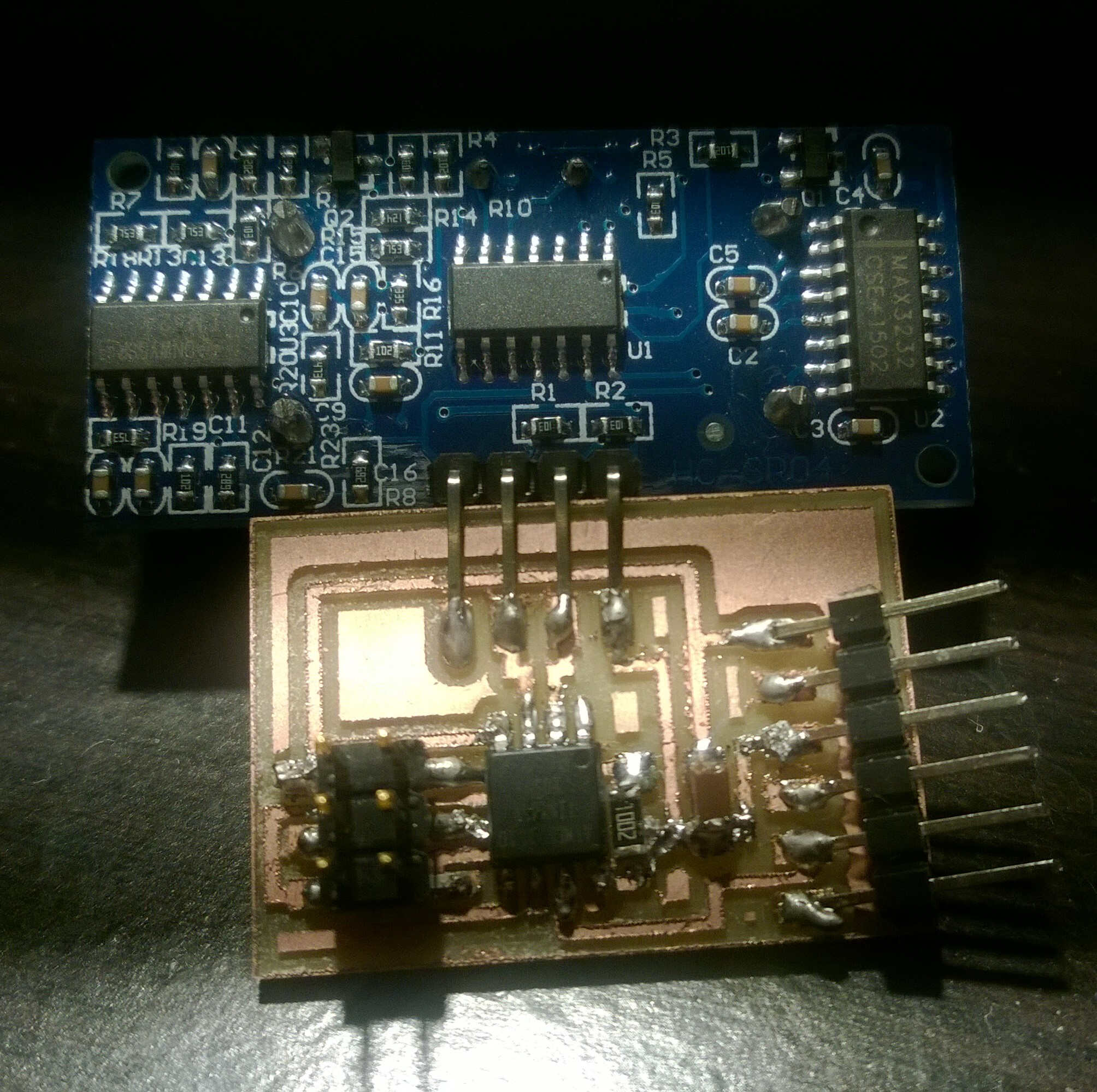
sonar soldered
powering
Also by accident the soldering iron tip touched the Attiny45. I wonder if it is still operationnal. I would like to purchase a microcontroller clamp to be able to check that (such as those from TAG CONNECT). Apparently those can also be built with 3D printers and pogo pins. Weeks later I was able to resolder and program the board. The only problem was to retrieve a distance.
The code I used to test:
    #include <avr/io.h>
#include <util/delay.h>

#define output(directions,pin) (directions |= pin) // set port direction for output
#define set(port,pin) (port |= pin) // set port pin
#define clear(port,pin) (port &= (~pin)) // clear port pin
#define pin_test(pins,pin) (pins & pin) // test for port pin
#define bit_test(byte,bit) (byte & (1 << bit)) // test for bit set
#define bit_delay_time 102 // bit delay for 9600 with overhead
#define bit_delay() _delay_us(bit_delay_time) // RS232 bit delay
#define half_bit_delay() _delay_us(bit_delay_time/2) // RS232 half bit delay
#define char_delay() _delay_ms(10) // char delay

#define serial_port PORTB
#define serial_direction DDRB
#define serial_pin_out (1 << PB2)
#define trigger_port PORTB
#define trigger_direction DDRB
#define trigger_pin (1 << PB3)
#define echo_pins PINB
#define echo_direction DDRB
#define echo_pin (1 << PB4)

#define timeout 255

void put_char(volatile unsigned char *port, unsigned char pin, char txchar) {
   //
   // send character in txchar on port pin
   //    assumes line driver (inverts bits)
   //
   // start bit
   //
   clear(*port,pin);
   bit_delay();
   //
   // unrolled loop to write data bits
   //
   if bit_test(txchar,0)
      set(*port,pin);
   else
      clear(*port,pin);
   bit_delay();
   if bit_test(txchar,1)
      set(*port,pin);
   else
      clear(*port,pin);
   bit_delay();
   if bit_test(txchar,2)
      set(*port,pin);
   else
      clear(*port,pin);
   bit_delay();
   if bit_test(txchar,3)
      set(*port,pin);
   else
      clear(*port,pin);
   bit_delay();
   if bit_test(txchar,4)
      set(*port,pin);
   else
      clear(*port,pin);
   bit_delay();
   if bit_test(txchar,5)
      set(*port,pin);
   else
      clear(*port,pin);
   bit_delay();
   if bit_test(txchar,6)
      set(*port,pin);
   else
      clear(*port,pin);
   bit_delay();
   if bit_test(txchar,7)
      set(*port,pin);
   else
      clear(*port,pin);
   bit_delay();
   //
   // stop bit
   //
   set(*port,pin);
   bit_delay();
   //
   // char delay
   //
   bit_delay();
   }

int main(void) {
   //
   // main
   //
   static unsigned char high,low;
   //
   // set clock divider to /1
   //
   CLKPR = (1 << CLKPCE);
   CLKPR = (0 << CLKPS3) | (0 << CLKPS2) | (0 << CLKPS1) | (0 << CLKPS0);
   //
   // initialize output pins
   //
   set(serial_port,serial_pin_out);
   output(serial_direction,serial_pin_out);
   clear(trigger_port,trigger_pin);
   output(trigger_direction,trigger_pin);
   //
   // start counter
   //
   TCCR0B |= (1 << CS00); // prescale /1
   //
   // main loop
   //
   while (1) {
      //
      // trigger pulse
      //
      set(trigger_port,trigger_pin);
      _delay_us(10);
      clear(trigger_port,trigger_pin);
      //
      // wait for echo rising edge
      //
      high = 0;
      TCNT0 = 0;
      TIFR |= (1 << TOV0);
      while (1) {
         if ((echo_pins & echo_pin) != 0) // check for rising edge
            break;
         if ((TIFR & (1 << TOV0)) != 0) { // check for counter overflow
            high += 1;
            if (high == timeout)
               break;
            TIFR |= (1 << TOV0);
            }
         }
      //
      // rising edge found, wait for falling edge
      //
      high = 0;
      TCNT0 = 0;
      TIFR |= (1 << TOV0);
      while (1) {
         if ((echo_pins & echo_pin) == 0) { // check for falling edge
            low = TCNT0;
            break;
            }
         if ((TIFR & (1 << TOV0)) != 0) { // check for counter overflow
            high += 1;
            if (high == timeout)
               break;
            TIFR |= (1 << TOV0);
            }
         }
      //
      // send count with framing
      //
      put_char(&serial_port,serial_pin_out,1);
      put_char(&serial_port,serial_pin_out,2);
      put_char(&serial_port,serial_pin_out,3);
      put_char(&serial_port,serial_pin_out,4);
      put_char(&serial_port,serial_pin_out,low);
      put_char(&serial_port,serial_pin_out,high);
      //
      // delay before next cycle
      //
      _delay_ms(10);
      }
   }
Back to basics
I know a Attiny has a temperature in-sensor, this webpage will help me make good use of it. I will build a minimalist board with an Attiny 45, a capacitor, a resistance, a crystal, FTDI pins and ISP headers.
Board conception
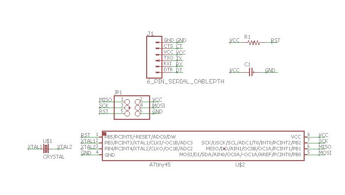
board schematics
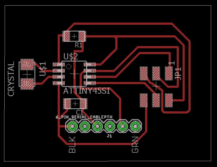
board route
Source file to load here
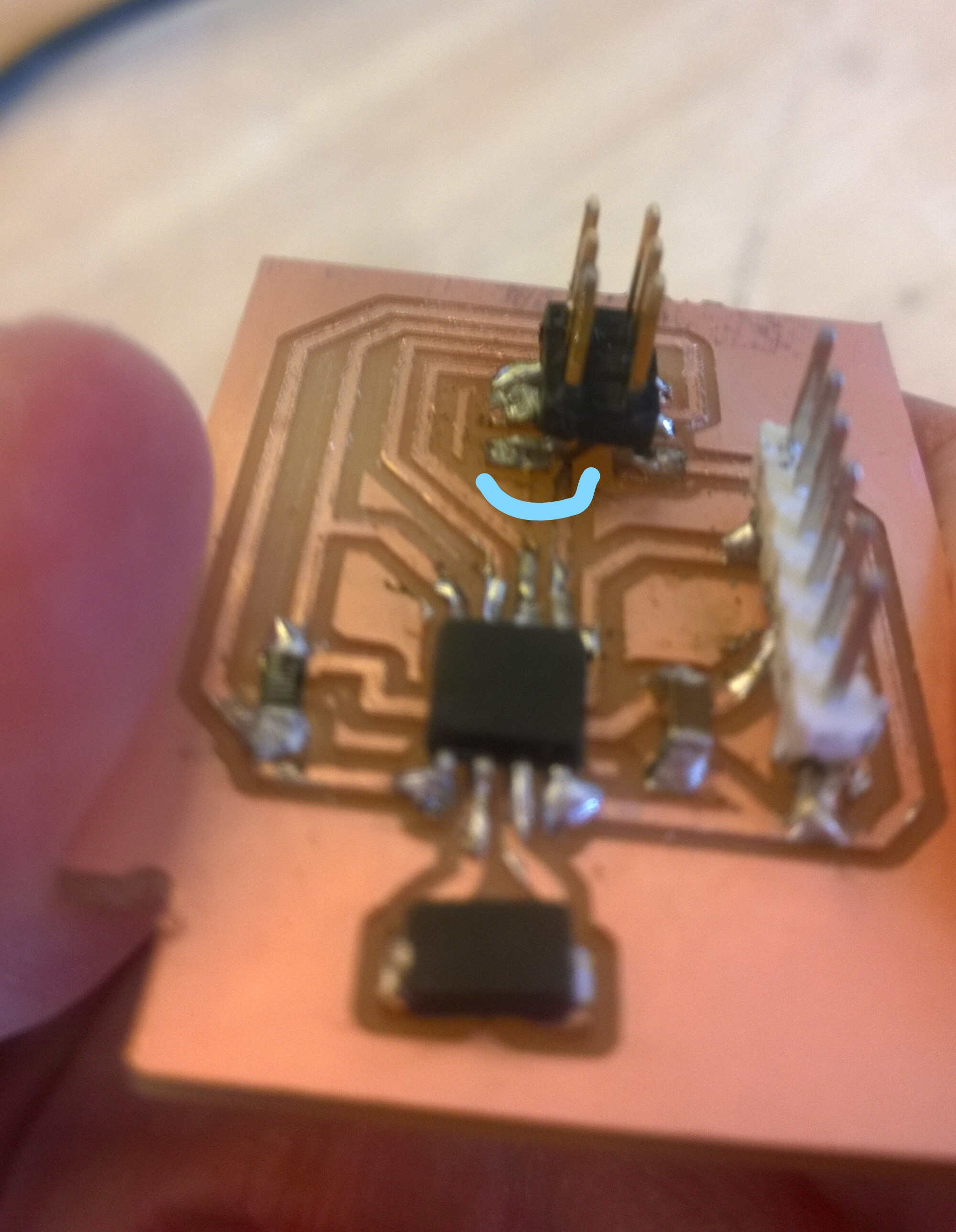
Board soldering
First attempt at soldering ended up with a short-circuit. This was caused by a surplus of solder. I noticed that a good practice was to take a picture of the board milled to pinpooint likely short-circuiting places.
close traces
solder short-circuiting
Programming
I struggled to compile the code provided on the first blog, so I found another one. Helping blog (on the serial communication option).
Code deciphering and reworking
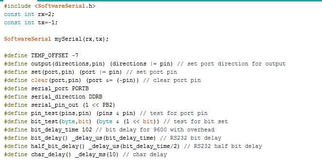
include
In the first part the serial library had to be replaced by SoftwareSerial as I am not using an Arduino. SoftwareSerial takes two parameters as input rx and tx. From what I understood they correspond to the pin number corresponding. As in my board I am not sending data, I am not using Tx hence tx = -1. Rx is connected to PB2 hence rx = 2. Despite the deciphering I couldn't make this code work I decided to rework Neil's temperature code.
Neil's code
Neil doesn't use a serial library, he directly codes the serial communication which makes the code more compact.
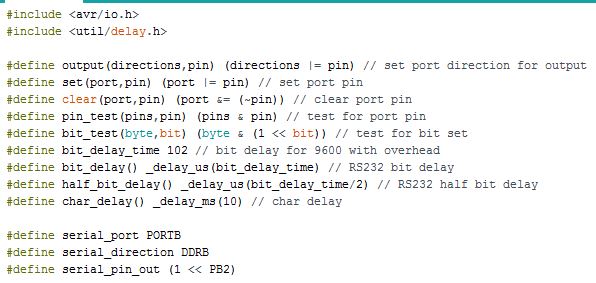
include
Neil defines functions at the start of the code mainly to manage the ports. Bit delay time is related to the baud rate. Operating at 9600 bauds means the state can be changed 9600 times/s, hence every bit last 1/9600 s (104 microseconds) This explanation helped understand serial.

put_char function
Put_char function converts bit to octets I think. Reminder: a byte is a sequence of bit [0,1]. Serial communication relies on octet (sets of 8 bits).
setup
- In the setup the clock divider is set to 1 -I am unsure of it as in the documentation it says it is put at 2 if CLKPS0/1/2/3 are set to 0 (As the internal clock runs at 8 MHz, it is running at 8MHz. Serial communication should use a clock at a maximum of 1MHz.)
- The output pin is set to PB2.
- And the analog comparator is activated (ADEN set to 1). For the in-situ temperature sensor the voltage reference should be the internal 1.1V (done by setting MUX0/1/2/3 to 1) The data in the comparator register is adjusted to the right (ADLAR = 0). The conversion can take place in both directions (BIN set to 1). And a prescaler is used to defined the A/C comparator clock. (ADPS2 = 0; ADPS1/0 = 1) Here the AC comparator clock is the board clock/8. So the input of the A/C comparator arrives at 1MHz(Serial communication should use a clock at a maximum of 1MHz). Neil used a prescaler /128, this corresponds to a 62.5 kHz frequency.
loop
In the main loop, framing is inserted, conversion is activated and the result is send in 2 parts because ADC generates a 10 bit output.
FTDI convertor
I struggled several days with the FTDI driver installation...before realizing the FTDI convertor I was using was faulty. I am using a Trixi FTDI232 with a FTDI232RL chip.
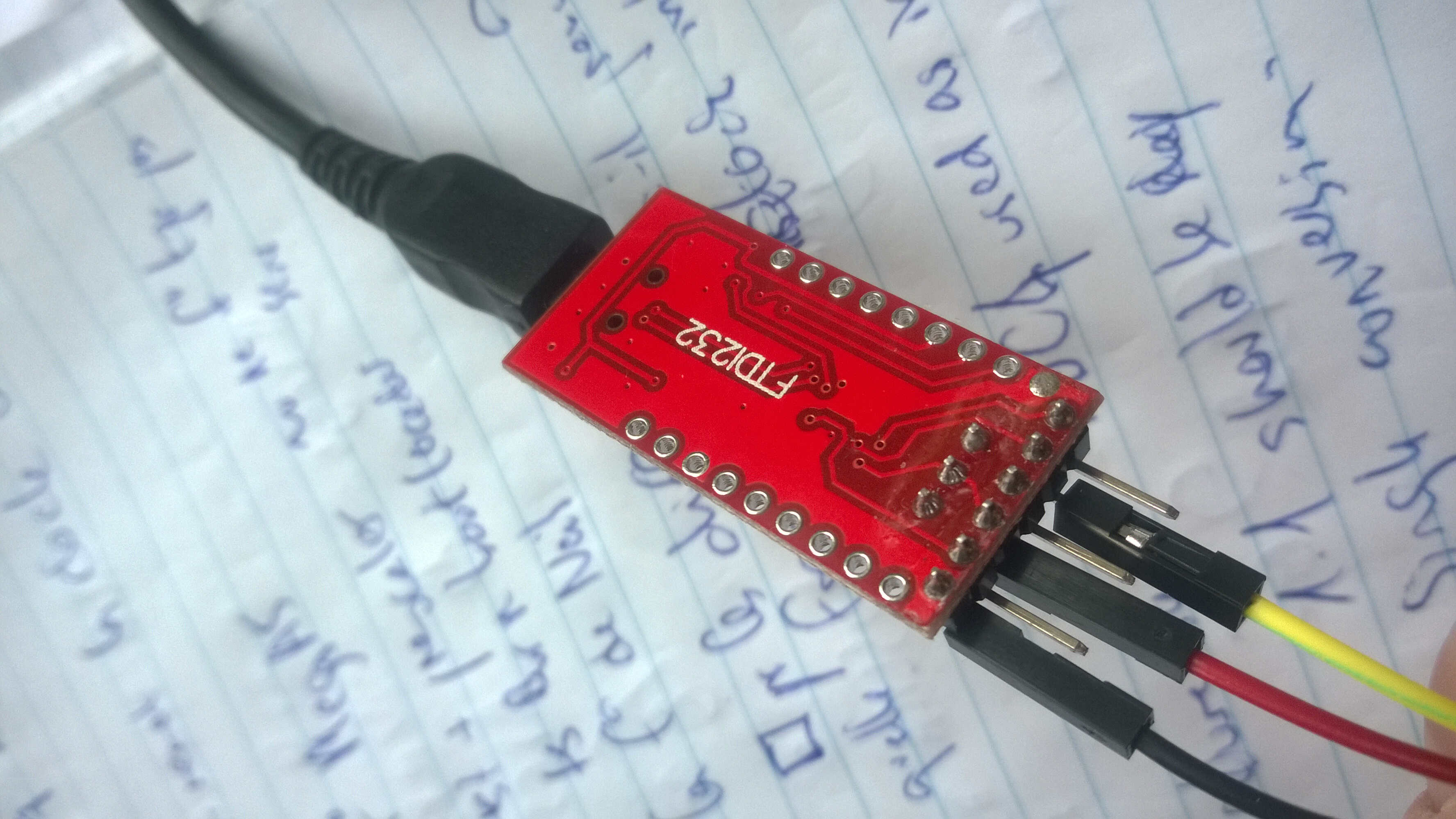
FTDI232
They are nonetheless a few precautions to take when installing FTDI driver on Windows 10 64 bits. Those drivers can be found on this page and in case of error this manual can be of great help. Because my convertor was faulty I kept having a warning sign in the device manager and when displaying the port properties a error was notified (Error 10).
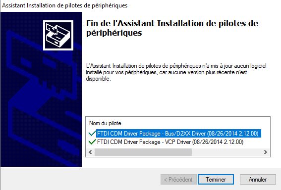
FTDI installation went fine
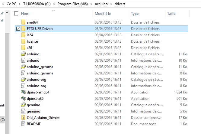
FTDI USB driver installed with Arduino
driver stored in Windows sytem
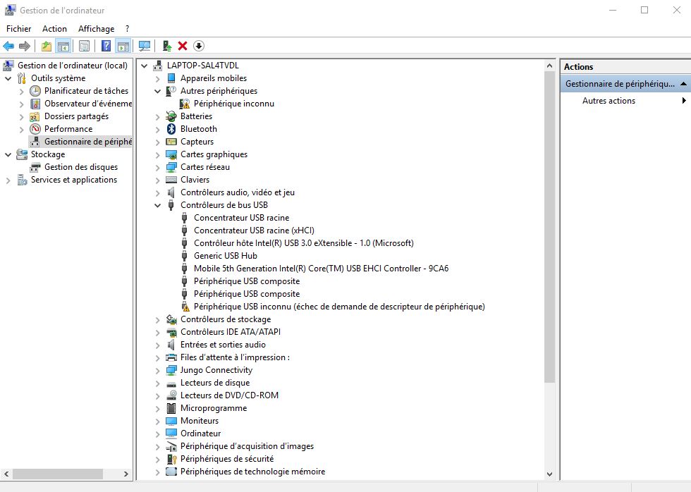
device manager

COM error
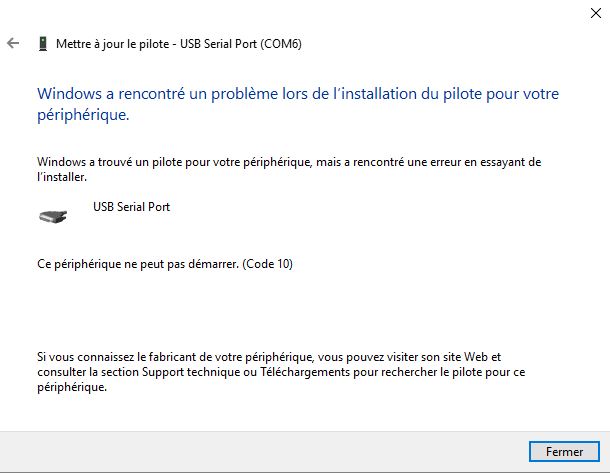
Error 10
Python
I tried to understand how to retrieve data. From observing the input week scripts given by Neil I supposed that the C code was needed to program the board and a .py file was needed to display the data. I have been told later that data could be displayed with the serial monitor but the Python scripts made the display more readable and allow data treatment. I downloaded packages to make Neil's script readable with my Python IDLE. I had to install numpy, but in order to be able to install it I needed cython first and Microsoft visual C++. Numpy install is quite impressive, a lot of files are loaded.
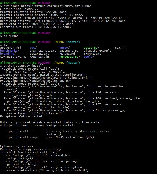
numpy > cython
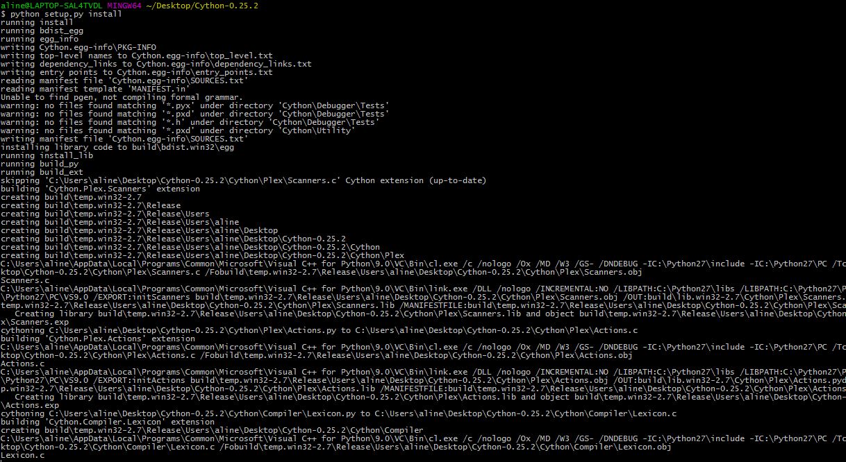
cython install
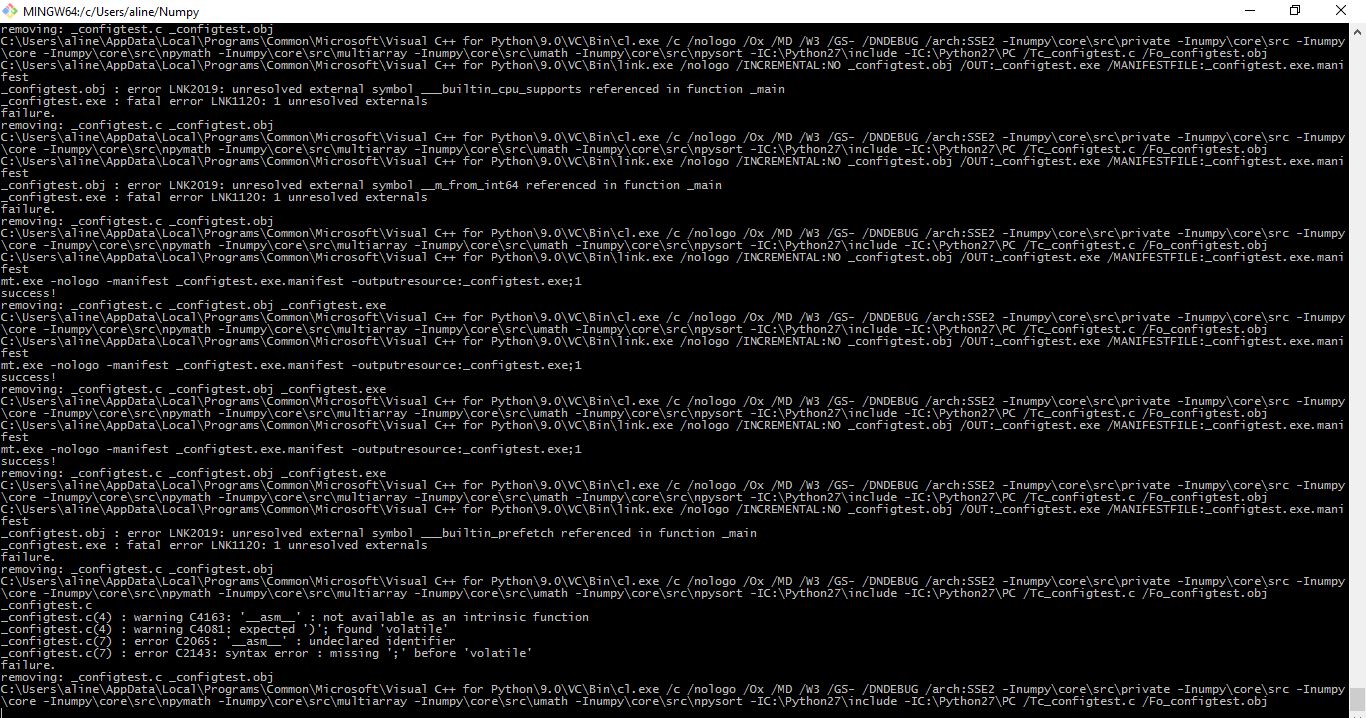
numpy long install
Once everything was installed I tried to launch the temperature Python script provided by Neil's. It paused after displaying this:
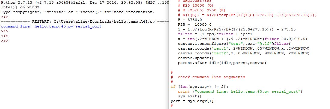
display and code (right)
I suppose this means there is an issue with the port or maybe with the FDTI connexion. So I went back to Arduino IDE to use the serial monitor.
Serial Arduino IDE
Once modified Neil's code was charged in the board flash, the serial monitor displayed characters that made no sense. So I decided to run a battery of tests.
I realized that the board I designed was really similar to the echo board I soldered a couple of week back. I didn't test the echo as at the time we didn't have FTDI convertors. So I loaded Neil's echo code and the serial monitor also displayed clumsy characters as shown in this video:
Then I realized I selected the wrong internal clock. I selected 1MHz instead of 8MHz. Once the correction made the echo worked perfectly.
I thought I figured out my mistake, so I went back to my temperature in-sensor board and I changed the clock to 8MHz. I even burned the bootloader. But this didn't fix the issue. I think my clocks are not synchronized. I tried different tests:
- comment the clock modification (CLPCE/CLKPSX)
- comment the A/D converter prescaler (ADPS2)
- changed the voltage reference to 2.56V
- comment BIN
At every try I looked at the display after selecting different baud rates. But I couldn't find the right combinaison, instead of having numbers and got squares. I checked that PB2 was functionning: I heated the microcontroller and I could see changes in the output.
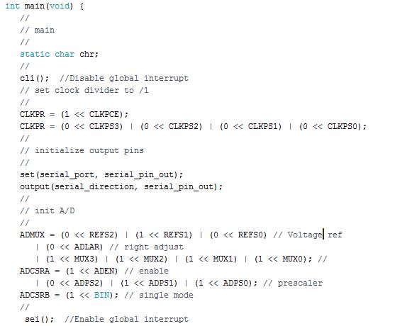
Here the code is flashed:
#include <avr/io.h>
#include <util/delay.h>
#define output(directions,pin) (directions |= pin) // set port direction for output
#define set(port,pin) (port |= pin) // set port pin
#define clear(port,pin) (port &= (~pin)) // clear port pin
#define pin_test(pins,pin) (pins & pin) // test for port pin
#define bit_test(byte,bit) (byte & (1 << bit)) // test for bit set
#define bit_delay_time 102 // bit delay for 9600 with overhead
#define bit_delay() _delay_us(bit_delay_time) // RS232 bit delay
#define half_bit_delay() _delay_us(bit_delay_time/2) // RS232 half bit delay
#define char_delay() _delay_ms(10) // char delay
#define serial_port PORTB
#define serial_direction DDRB
#define serial_pin_out (1 << PB2)
void put_char(volatile unsigned char *port, unsigned char pin, char txchar) {
//
// send character in txchar on port pin
// assumes line driver (inverts bits)
//
// start bit
//
clear(*port,pin);
bit_delay();
//
// unrolled loop to write data bits
//
if bit_test(txchar,0)
set(*port,pin);
else
clear(*port,pin);
bit_delay();
if bit_test(txchar,1)
set(*port,pin);
else
clear(*port,pin);
bit_delay();
if bit_test(txchar,2)
set(*port,pin);
else
clear(*port,pin);
bit_delay();
if bit_test(txchar,3)
set(*port,pin);
else
clear(*port,pin);
bit_delay();
if bit_test(txchar,4)
set(*port,pin);
else
clear(*port,pin);
bit_delay();
if bit_test(txchar,5)
set(*port,pin);
else
clear(*port,pin);
bit_delay();
if bit_test(txchar,6)
set(*port,pin);
else
clear(*port,pin);
bit_delay();
if bit_test(txchar,7)
set(*port,pin);
else
clear(*port,pin);
bit_delay();
//
// stop bit
//
set(*port,pin);
bit_delay();
//
// char delay
//
bit_delay();
}
int main(void) {
//
// main
//
static char chr;
static char conv;
//
cli(); //Disable global interrupt
// set clock divider to /1
//
CLKPR = (1 << CLKPCE);
CLKPR = (0 << CLKPS3) | (0 << CLKPS2) | (0 << CLKPS1) | (0 << CLKPS0);
//
// initialize output pins
//
set(serial_port, serial_pin_out);
output(serial_direction, serial_pin_out);
//
// init A/D
//
ADMUX = (0 << REFS2) | (1 << REFS1) | (0 << REFS0) // Voltage ref
| (0 << ADLAR) // right adjust
| (1 << MUX3) | (1 << MUX2) | (1 << MUX1) | (1 << MUX0); //
ADCSRA = (1 << ADEN) // enable
| (0 << ADPS2) | (1 << ADPS1) | (1 << ADPS0); // prescaler
ADCSRB = (1 << BIN); // single mode
//
sei(); //Enable global interrupt
// main loop
//
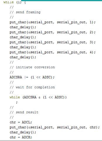
while (1) {
//
// send framing
//
put_char(&serial_port, serial_pin_out, 1);
char_delay();
put_char(&serial_port, serial_pin_out, 2);
char_delay();
put_char(&serial_port, serial_pin_out, 3);
char_delay();
put_char(&serial_port, serial_pin_out, 4);
char_delay();
//
// initiate conversion
//
ADCSRA |= (1 << ADSC);
//
// wait for completion
//
while (ADCSRA & (1 << ADSC))
;
//
// send result
//
chr = ADCL;
put_char(&serial_port, serial_pin_out, chr);
char_delay();
chr = ADCH;
put_char(&serial_port, serial_pin_out, chr);
char_delay();
//conv= 256*ADCH+ADCL;
//put_char(&serial_port, serial_pin_out, conv);
//char_delay();
}
}
In order to complete the course I redesigned a board with a phototransistor to have an input device on a board I designed. I used the design of a previous board, the one with traffic lights from Output week.
On this board I put:
-a FTDI connector
-a ISP connector
-a phototransistor
-a voltage divider resistor related to the phototransistor
-a couple of VCC/GND pins
For the voltage divider I found the inspiration in Jeff's page. I wondered why he put one, remembered than analog pins could handle voltage up to 1V. I then looked at the phototransistor datasheet. I read that the collector voltage could go up to 70V. After some more research this is actually a pull-up resistor as explained on this page. With my setting the voltage will go high as the light goes down. If I would like the voltage to go up as the light increases I should reverse the phototransistor and the resistor. But as I read in the datasheet all Attiny 44 pins have pull up resistor, so this resistor might be optional. I looked at Eagle board and at the datasheet to know how the phototransistor was polarized.
schematics
board
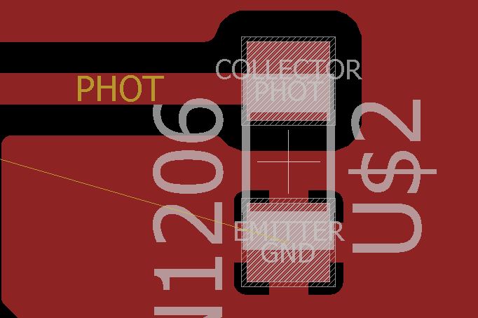
phototransistor polarity

phototransistor polarity datasheet
For this board again I used a ground plane and again couldn't unify it so I used 2 0 ohm resistors to bridge the 3 separate planes.
For the code I used SoftwareSerial library. I made tests with Rx as PB0 and Tx as PB1 but those pins seem not to be usable for this purpose maybe because they are not analog pins. Then I decided to use MISO as Rx and SCK as Tx. It then worked. I could read values on the serial monitor and they varied in function of the luminosity. The darker the higher the number displayed. This suggest that I could remove from a version 2 most of the pins and only keep the ISP ones, which could be used for flash and for serial.
#include <SoftwareSerial.h>
#define rxPin PA5
#define txPin PA4
#define pho PA7

SoftwareSerial mySerial(rxPin, txPin);
void setup() {
  pinMode(rxPin, INPUT);
  pinMode(pho, INPUT);
  pinMode(txPin, OUTPUT);
  // put your setup code here, to run once:
mySerial.begin(1200);
mySerial.println("hello");
}

void loop() {
  // put your main code here, to run repeatedly:

int sensorValue = analogRead(pho);
mySerial.println(sensorValue);
delay(100);
}
Source file to load here
As specified my step response tentative was related to my project and to the tile design.
Also the temperature sensor is a way to progress on my final project as i would like to work with small low-power low-ressource circuits. Once it will work I would like to go a step further by testing the sleep mode and reducing frequency.
Regional
I got impressed by Joris's progress, the fact that he used a audio cable, I2C protocol and considered building his own library. I went to check his code as he was also measuring temperature but it was not documented.
I also liked Miguele's work with lamps and valves but it was undocumented as well.
I asked for help with my FTDI issue, Roman thought it was due to the drivers.
General
List of inputs used: phototransistor, sonar, temperature, capacitive step response [...]