Week 11 - Machine Design
Group Assignment
- automate your machine, document the group project and your individual contribution.
Group project page
Initially I tested a user interaction solution based on the powerful computer vision library OpenCV. Later, I moved to a Telegram bot for interfacing the machine to a smartphone.
On the machine side, I connected the electromagnet to the board I designed during week 10 and I wrote the code for controlling the activation of the magnetic field directly from the PC. Moreover, I wrote the code needed to communicate with the gestalt nodes, which move the motors and draw the X or O symbols within the cells of the game.
Finally, I integrated all the code in a single Python script which handles the Telegram messages, moves the motors and manages the remote activation of the electromagnet.
OpenCV
Initially, I played a bit with Python and OpenCV to create a possible vision system able to detect automatically the X and O on a whiteboard: using a camera and the Hough transform (plus a few filtering tricks), I was able to detect crosses and circles.
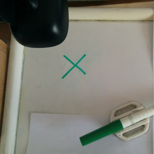
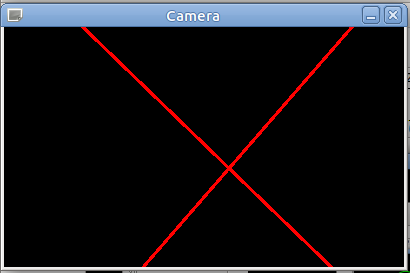
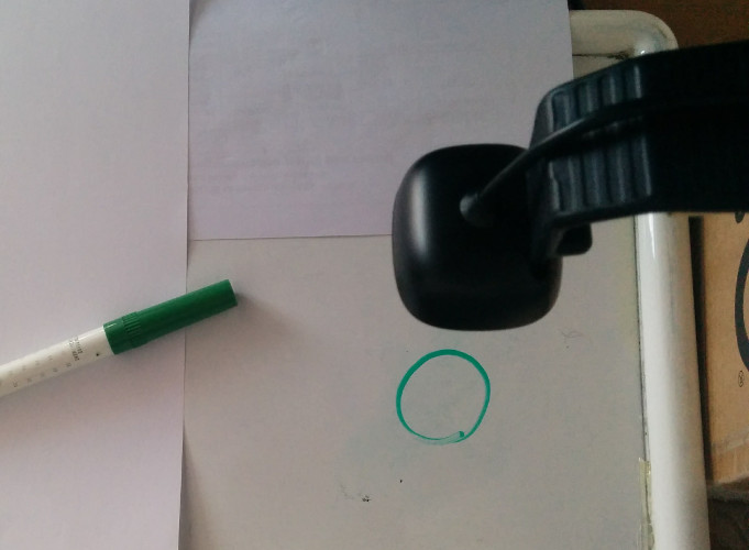
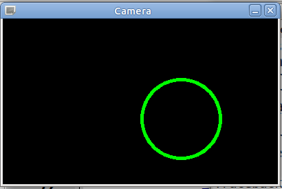
As you can see in the video below, we have a rough system for detecting cross and circles. So we will be able to play on a whiteboard with a marker and the camera will detect cross and circles.
I originally planned to have a fixed grid on a board and a fixed camera aligned to the grid. Hence, I would have been able to consider the 9 squares of the game independently, looking for X and O in each of them.
A rough implementation in Python is available for download at the bottom of the page.
Telegram bot
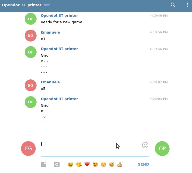
So, I started investigating a vision system for controlling the machine. However, after a discussion within the Opendot group, we came to the conclusion of using a Telegram Bot for controlling the machine. The idea is to use a bot to collect moves from a smartphone and replicate them physically. For example, sending the command X5 to the bot will result in an X on the fifth cell (they are numbered from 1 to 9).
Following this tutorial, I registered a new bot on Telegram and downloaded the telepot library for creating a simple bot in python.
I implemented a few valid commands (the code is at the bottom of the page):
- X# or O# - move (if valid)
- /schema - show the current grid with the moves (X and O)
- /reset - start a new game
The core function of the bot which handle received Telegram messages is show below:
def handle(msg):
	chat_id = msg['chat']['id']
	command = msg['text']

	cmd = parse_command(command)
	if cmd is not None:
		if play(cmd[0], cmd[1]-1):
			bot.sendMessage(chat_id, printable_grid())
		else:
			bot.sendMessage(chat_id, 'Cell already taken!')
			bot.sendMessage(chat_id, printable_grid())
	elif command == '/schema':
		bot.sendMessage(chat_id, printable_grid())
	elif command == '/reset':
		reset()
		bot.sendMessage(chat_id, "Ready for a new game")
	else:
		bot.sendMessage(chat_id, "invalid command")
As you can see, the command is analyzed by an external 'parse_command' function I wrote to check if the message is a valid move, that is X or O followed by a number between 1 and 9. A sequence of if/elif is used to take the right action in response to the message.
Below you can see the bot in action from the Telegram web app!
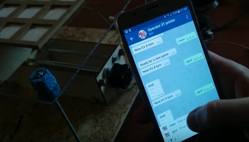
And from my Android smartphone!
Electromagnet
In week 9 I found and tested the electromagnet, which is a crucial component of the machine: instead of using a permanent magnet and a Z-axis movements, we decided to fix the Z position and use an electromagnet, activating it when needed to move the magnet of each cell.
My task was to coordinate the XY movements of the motors, driven by the command given to the telegram bot, with the on-off activation of the electromagnet.
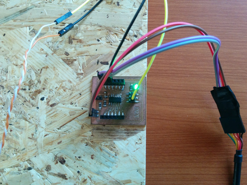
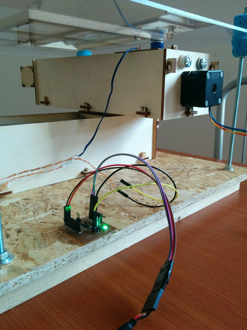
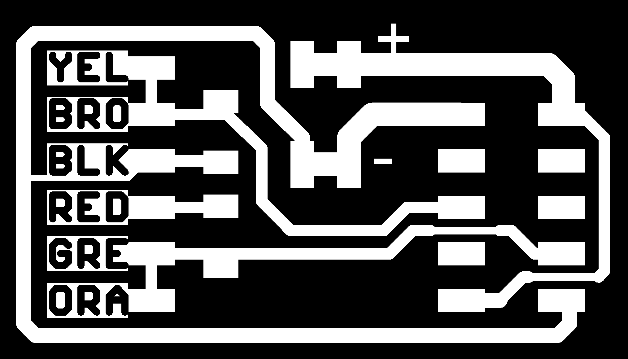
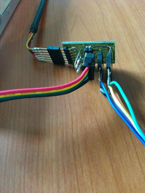
During past week 10 I designed a minimal general purpose board which can be programmed and, most important, easily expanded and connected to inputs and outputs. I used the same board for controlling the electromagnet: I connected GND to one of its wires and the other to onboard pin A2. I also connected ATtiny pins A0 and A1 to the RX and TX pins of the FTDI cable. The FTDI USB cable also powers the board providing 5 V.
The idea is quite simple: when we need to activate the electromagnet to capture the metallic drawing object, we send a simple message to the board. The board receives the message from the serial port, parses it and recognizes that it is an activation message (byte equal to 1). Hence, it switches to high the pin to which the magnet is attached. Similarly, when a message equal to 2 is received from the serial port, the board turns the pin to low disabling the electromagnet.
According to the ATtiny44 datasheet (see week 8), the maximum DC current output for an I/O pin on the ATTiny44 is 40 mA. The electromagnet has a resistance of 50 Ohm - according to Ohm's Law, 5 V / 50 Ω = 100 mA, a value higher than the maximum output. This means that the current flowing through the wire of the electromagnet will be limited only by the microcontroller to 40 mA.
PIN CURRENT
The datasheet warns that exposure to absolute maximum rating conditions of 40 mA for extended periods may affect device reliability. Since the magnet will be activated for just a few seconds during each move, it is acceptable to attach it directly to the pin of the microcontroller. In production, an external power source and a driving circuit with a transistor should be used.I wrote a small Arduino code which parses the message codes received from the Serial port and turns on (msg=1) or off (msg=2) the electromagnet on pin A2, and I uploaded it to the board.
#include <SoftwareSerial.h>

SoftwareSerial mySerial(PIN_A0, PIN_A1);

#define MAGNET_PIN A2
#define ON 1
#define OFF 0

#define MSG_MAGNET_ON 1
#define MSG_MAGNET_OFF 2

byte cmd = 0;

void setup() {
  pinMode(MAGNET_PIN, OUTPUT);
  mySerial.begin(9600);
  digitalWrite(MAGNET_PIN, LOW);
}

void loop() {
  if (mySerial.available() > 0) {
    cmd = mySerial.read();
    if (cmd == MSG_MAGNET_ON) {
      magnet(ON);
    } else if (cmd == MSG_MAGNET_OFF) {
      magnet(OFF);
    }
  }
  delay(5);
}

void magnet(int power) {
  if (power) {
    digitalWrite(MAGNET_PIN, HIGH);
  } else {
    digitalWrite(MAGNET_PIN, LOW);
  }
}
Python is the language used to control also the Telegram bot and the motors attached to the gestalt nodes. Controlling also the ATtiny and its electromagnet from Python seemed to me the most natural choice. Sending serial messages in Python is quite easy. You just need to open the serial port:
import serial
ser = serial.Serial('/dev/ttyUSB0', 9600)
and then sending the bytes of the messages (1 or 2) is as easy as writing
ser.write(b'\x01')
ser.write(b'\x02')
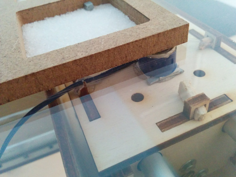
Finally, we fixed the electromagnet on the top of the two moving axes. As you can see below, it has been positioned a few millimeters under the Plexiglas ready to draw X and O capturing within its magnetic field one of the small squared objects.
XY motors
Firstly, I played a bit with the X and Y motors, controlled by a pair of gestalt nodes.
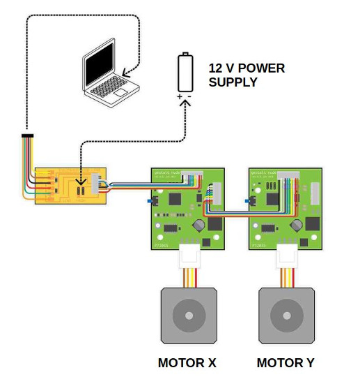
The physical layer used to communicate with Gestalt Nodes is called Fabnet and is a sort of RS-485 bus with a few additional signals. Hence, you cannot connect directly a standard USB RS-485 cable to the computer: you need a "bridge" board that adapts the 485 cable to Fabnet using a pair of 600 ohm pull up/down resistors. Moreover, this board is also needed to provide power to the whole network: all of the nodes have a regulator and are getting power from the line marked "high" on the board. It is worth noticing that the 5V USB power source is not enough: considering the stepper motor used in the project, the source should be 12V. Finally, you need to connect 6 signals from the board to the first Node of the Gestalt "network".
I used the board designed by Bas, which allows you to use a straight through ribbon cable to connect the first Node. I powered the board using a 12V switching power supply.
The resulting board is simple but works nicely.
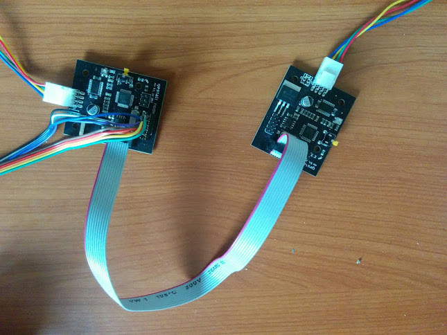
I connected the two Nodes to the board: the first was the X, then the Y. The setup for the machine and the nodes physically connected follow:
Now I was ready to move the motors! I downloaded the pygestalt code and cloned the repo locally with:
git clone https://github.com/nadya/pygestalt.gitI moved into the directory pygestalt and ran setup.py to install it
cd pygestalt
sudo python ./setup.py install
At this point, I moved into the directory examples/machines/htmaa and I had a look at the singlenode.py to start learning how the Gestalt framework works.
The first time, I had to identify the two nodes pushing the buttons, hence I pushed first the X motor, then the Y one. I wrote a Python script which can be used to move the axes at the beginning to set the XY origin, then I improved the script to draw a cross and a circle.
As you can see in the excerpt below, I designed the movement of the circle using the sin a cos functions, while the cross is quite strange: the X is designed moving from one corner to all the others, passing each time through the center. This approach is needed because we cannot move the "pen" up or down, and we alway leave a track on the sand.
box = 10  # size of a cell in steps
l = int(box * math.sqrt(2) / 2)
r = box / 2

angles = [i/100.0 for i in range(0, int(math.pi*2*100), 10)]
circle = [[r-r*math.cos(angle), r-r*math.sin(alfa)] for alfa in angles]

cross = [[0, 0], [l, l], [2*l, 2*l], [l, l], [0, 2*l], [l, l], [2*l, 0], [l, l], [0, 0]]
System architecture
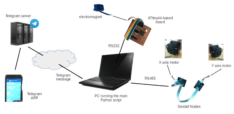
The final architecture of our Tic-tac-toe machine consists of four main parts: a Telegram-based communication and control channel, a network of gestalt-controlled motors, a simple USB-controlled electromagnet, and a computer running the software.
The computer which controls the machine connects to the Internet to receive Telegram messages. These messages are used to recognize the game move, position the motors using a pair of Gestalt nodes and activate/deactivate the electromagnet sending messages to an ATtiny44. In our group project we used a laptop, but a SBC (like a Raspberry Pi) would be fine as well.
The Internet connection requires an Ethernet cable or a WiFi card. The Gestalt nodes are controlled through an USB-RS485 cable plus the Fabnet adaptor. The ATtiny44 board communicates with the PC using a standard USB-RS232 cable.
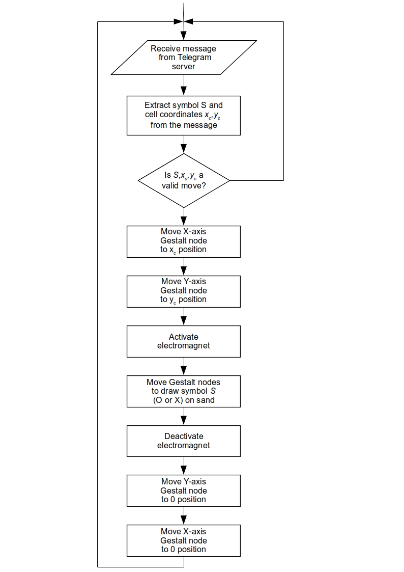
I integrated all the code fragments described above in a single Python script (see the tictactoe_machine.py script available below). This main script handles the Telegram messages, moves the motors and manages the remote activation of the electromagnet.
The algorithm, which is run inside and infinite loop, is the following:
Download zone - List of files
- opencv_machine.py - OpenCV test for detecting X and O
- opendottrisbot.py - Python Telegram Bot
- motorcontrol.py - Python code for setting XY origin and draw X and O
- magnet.ino - Arduino code for controlling the magnet
- serialmagnet.py - Python test code for controlling the magnet
- tictactoe_machine.py - Python code for running the machine