Week 10 - Output Devices
Assignment
- Add an output device to a microcontroller board you've designed and program it to do something.
Hellino - Redesigning the hello board
The assignment of this week was to add a sensor to my hello board designed a few weeks ago. However, instead of redesigning the board to accommodate a few output devices, I decided to take a different approach.
I took the original hello board, I removed all the unnecessary components, including the resonator (the internal 8 MHz clock is enough), I added a simple power-on LED and I exposed all the pins. The resulting board is a sort of Arduino: a general purpose board which can be programmed and, most important, expanded with shields.
As done during week 6, I designed the board in KiCad, processed the output SVG/PNG files with fabmodules and milled the board using the Roland MDX-40 available at Opendot.
I used the same parameters for fabmodules, but I'm writing it down here for clarity (reading my week 6 documentation, I missed a simple and clear table):
PCB traces (1/64)- speed (mm/s): 2
- x0 (mm/s): 0
- y0 (mm/s): 0
- z0 (mm/s): 0
- cut depth (mm): 0.09 ~ 0.1
- tool diameter (mm): 0.4
- n. of offsets: 2
- speed (mm/s): 4
- x0 (mm/s): 0
- y0 (mm/s): 0
- z0 (mm/s): 0
- cut depth (mm): 0.75
- stock thickness: 1.5
- tool diameter (mm): 2
- n. of offsets: 1
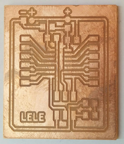
Please note that this week I used a brand new 0.4 mm end mill: the resulting PCB is wonderful!
As you can see, the BoM is minimal: one ATtiny44A, a few strips for programmers, all the data pins and VCC/GND, a capacitor, two resistors, one capacitor, a jumper and a LED (not necessary, but I added it for knowing when the board is powered).
Hellino Output module
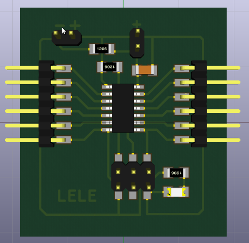
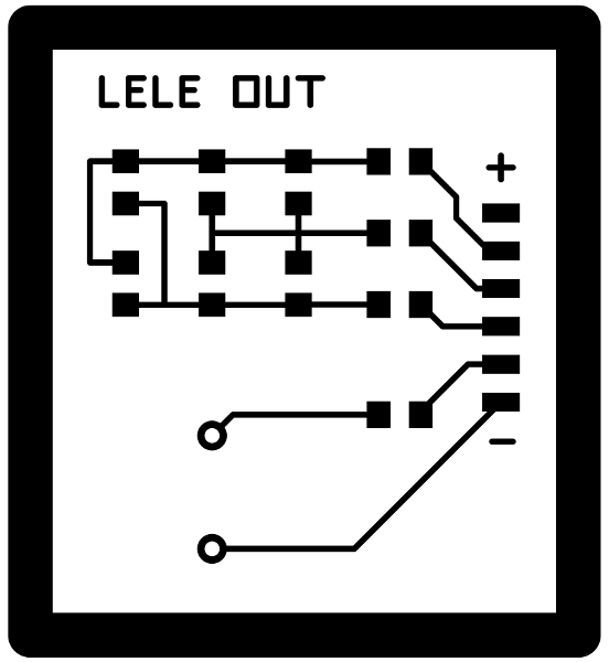
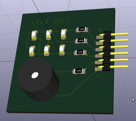
The Output module include two outputs: a LED matrix and a buzzer. I choose these two output devices since they are exactly what I planned to use in my Final Project.
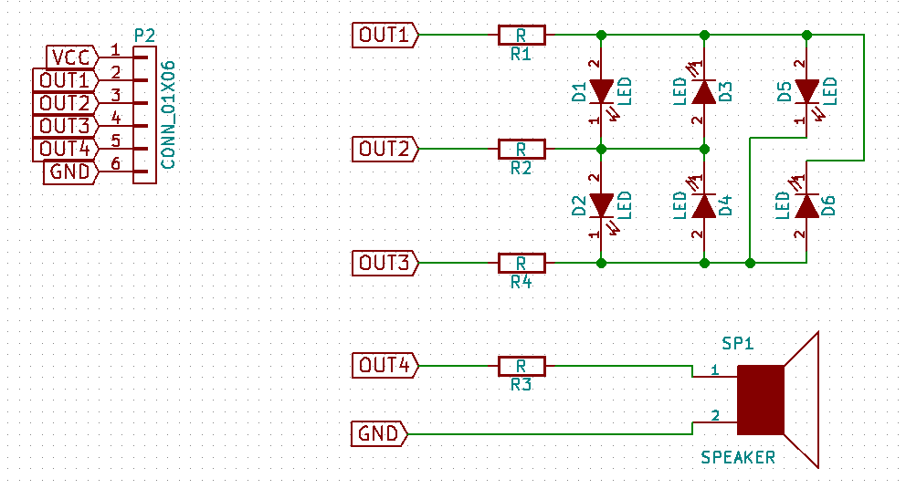
The schematic of buzzer (or piezo speaker) part is quite simple: it needs a resistor to moderate the current flowing out of the control pin, while the other pin of the buzzer is connected to ground.
For the LEDs, I used the Charlieplexing approach. I never heard of it before and I was fascinated by the principle: since saving pin will be important also for my final project, I read a bit about this solution on wikipedia and, then, I created a 6-LEDs matrix.
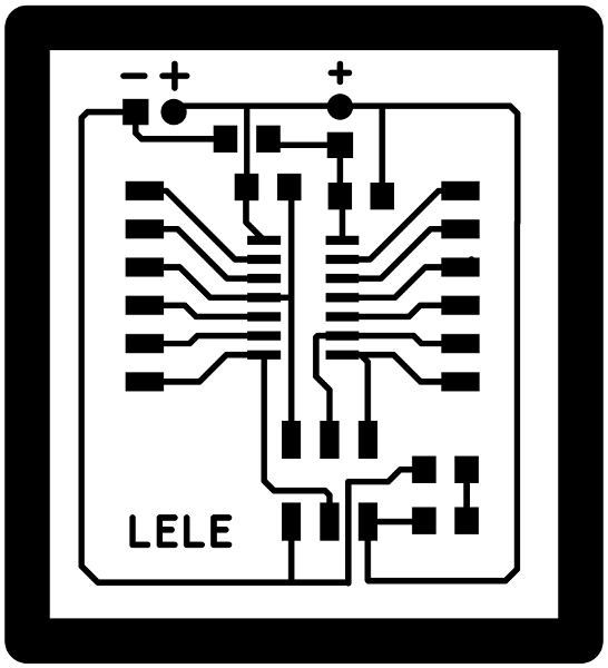
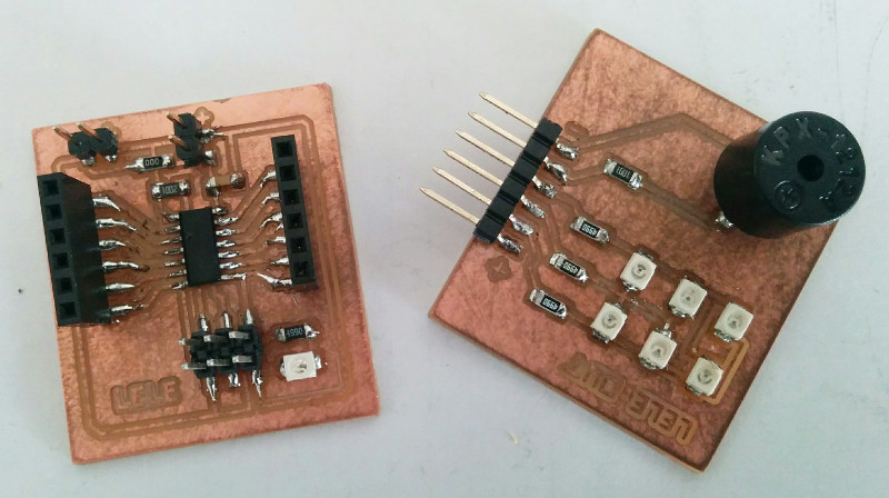
I milled the board as usual (see above for the settings) - the board was cut in a couple of minutes and without troubles:

Finally, I soldered all the components on both the boards.
Before programming the board, I burned the fuses of the hellino main module: I simplified the compute module as much as possible, removing the need for an external clock source. This is fine, but I need to recompute the fuses for using the internal calibrated 8 MHz clock instead of an external source with -U lfuse:w:0x62:m.
fuses and ATTiny44a
If you want to replicate this board, remember to set the internal clock source in the fuses .Programming outputs
I wrote a simple code for turning on and off the LEDs in the matrix according to a circular sequence. Since the matrix is based on
void flash(uint8_t from, uint8_t to, uint8_t delay) {
   set(led_port,from);
   clear(led_port,to);
   output(led_direction,from);
   output(led_direction,to);
   for (i = 0; i < delay; ++i)
       sleep_delay();
   input(led_direction,from);
   input(led_direction,to);
}
The function is called passing the two pins: the from, that is the pin on the anode side, and the to pin on the cathode. The other pin are not driven, so are in high-impedance mode, ensuring that no drive current flows into them. For example, since the first LED (the one on the bottom left of the board) can be switched on flowing current from pin1 to pin3, we can light it up for 100 ms calling flash(PA1, PA3, 100).
The buzzer can be simply turned on and off like a blinking LED with
   output(buzz_direction,buzz_pin);
   for (i = 0; i < delay; ++i)
       sleep_delay();
   input(buzz_direction,buzz_pin);
   for (i = 0; i < delay; ++i)
       sleep_delay();
The result is a board blinking and playing sound:
Inspired by the Arduino Melody tutorial, I rewrote the code in pure C for the ATtiny, without relying on external libraries. The idea is to use a piezo speaker to play melodies sending a square wave of the appropriate frequency to the piezo, generating the corresponding tone.
The code is available, as always, in the download section... But do not forget to listen the (nice?) sound of a piezo speaker.
Download zone - List of files
- hellino.zip Hellino board - KiCad project
- hellino_cut.zip Hellino board - SVG + PNG traces
- output.zip Output board - KiCad project
- output_cut.zip Output board - SVG + PNG traces
- output_code.tar.gz Code for LEDs and buzzer