Week 9 - Mechanical Design
Assignment
- Make a machine, including the end effector, build the passive parts and operate it manually.
Group project page

3T printer (sand-painting, remotely controlled tic-tac-toe machine)
The Structure
As Opendot Team, we discussed a few ideas (automatic checkers board, vertical plotter, zen garden, etc), and eventually we merged all the ideas in an automatic tic-tac-toe machine. To keep the original ideas of both plotting something and using send, we decided to develop a machine that could "magically" maneuver sand-like material using magnets (or metal squares) and create a Tic-Tac-Toe game usable by a remote application.
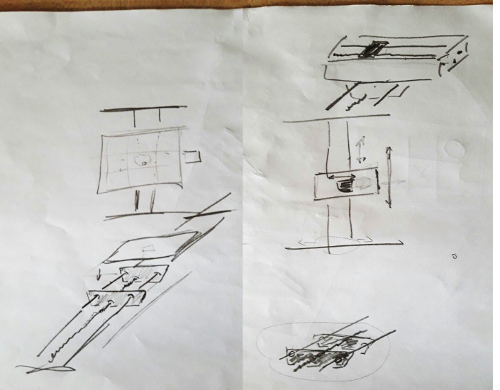
In this initial phase of the machine designed, I tried to help the team creating a common idea of the machine: I believed that, sharing a view of the final product, could have helped the development.
Inspired by the "Magic chess" and "Painting machine" mentioned in this how to make (almost) anything blog post, I sketched a possible design of the final machine.

As you can see below, the structure of the machine hosts the X and Y axis and a suspended plane for the game board (the top it should be floating to allow the "reset" of the game vibrating and, thus, flatting sand).
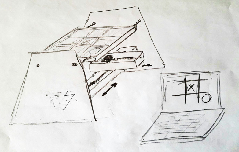
They are quite cryptic, but Cristiana translated them on a (much nicer) 3D computer model.
The Electromagnet
At this point, Pablo started working on the motorized X and Y axis, while I focused on the magnet. One design we evaluated was to use a regular magnet placed on a movable Z-axis below the board linked to another magnet to be placed above the board to sweep material away, but this was more complicated so we decided to eliminate this option. Instead, we choose to use an electromagnet that can be turned on and off, controlling the pick-up and drop-off of the metal squares. The advantage of the electromagnet lies in the removal of a third motor to control the Z axis.
After looking around and digging into some forgotten boxes stored in the attic, I found one of my old project: it was a rough and badly-soldered Arduino prototype shield for driving a small electromagnet.
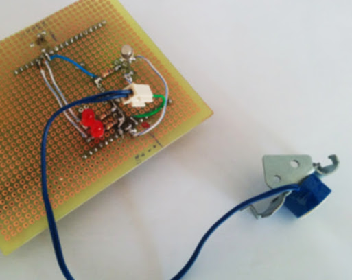
As you can see, I originally added a couple of LEDs and the circuitry to control the magnet using a BJT NPN transistor and a 10K resistor. This was needed for powering the electromagnet directly through the 9V coming from the Vin pin of the Arduino.
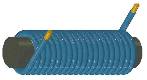
An electromagnet is is a type of magnet in which the magnetic field is produced by an electric current. Electromagnets usually consist of insulated wire wound into a coil. The wire turns are often wound around a core made from a ferromagnetic material such as iron - the core concentrates the flux into the center and strengthen the magnetic field. The strength of magnetic field generated is proportional to the amount of current through the winding.
Differently from permanent magnet, the magnetic field of an electromagnet disappears when the current is turned off. This feature makes the electromagnet the right choice for our project, where we would like to control the activation of the magnetic field.
I took away the electromagnet from my old circuit and I attached it directly to a 5V battery to simulate an high ATtiny output pin. No logic was involved in this first test: its aim was only to check that my electromagnet was still working.
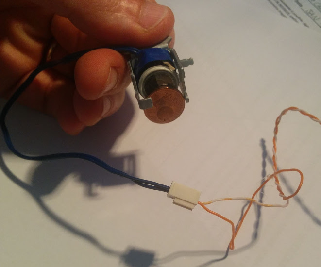
Hurrah! The electromagnet was dusty but still working like a charm. See the electromagnet in action holding (and releasing when powered off) a 1 cents coin:
Then, I tried Plexiglas with different thicknesses: the electromagnet is able to attract a small piece of metal with a 0.15 mm Plexiglas, while a small permanent magnet is attracted even using a 5 mm plane.