Final Project
QA BOX: test your culture!
Development
Bill Of Materials
- 1.40 m^2 of 3 mm Playwood;
- 0.05 m^2 of Plexiglass;
- 1 m^2 of OSB;
- 2 A4 sheets of White vynyl;
- 100g of Synthetic plaster;
- 100g of White PLA;
- Pcb copper plate;
- 1 ATtiny44;
- 5 SMD Buttons;
- 5 10KΩ Resistors;
- 1 100kΩ Resistor;
- 3 0 Resistors;
- 1 499Ω Resistor;
- 1 Piezo Spiker;
- 1 20MHz Resonator;
- 1 1uF Capacitor;
- 1 6x1 Pin Header;
- 1 3x2 Pin Header;
- 1 2x1 Pin Header;
- 1 3x1 Pin Header;
- 1 FTDI Cable;
- 1m of cable.
The Box
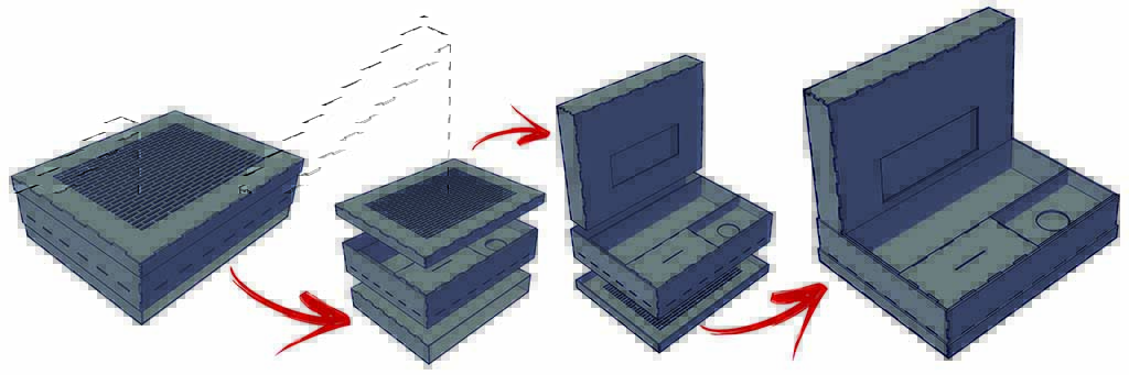
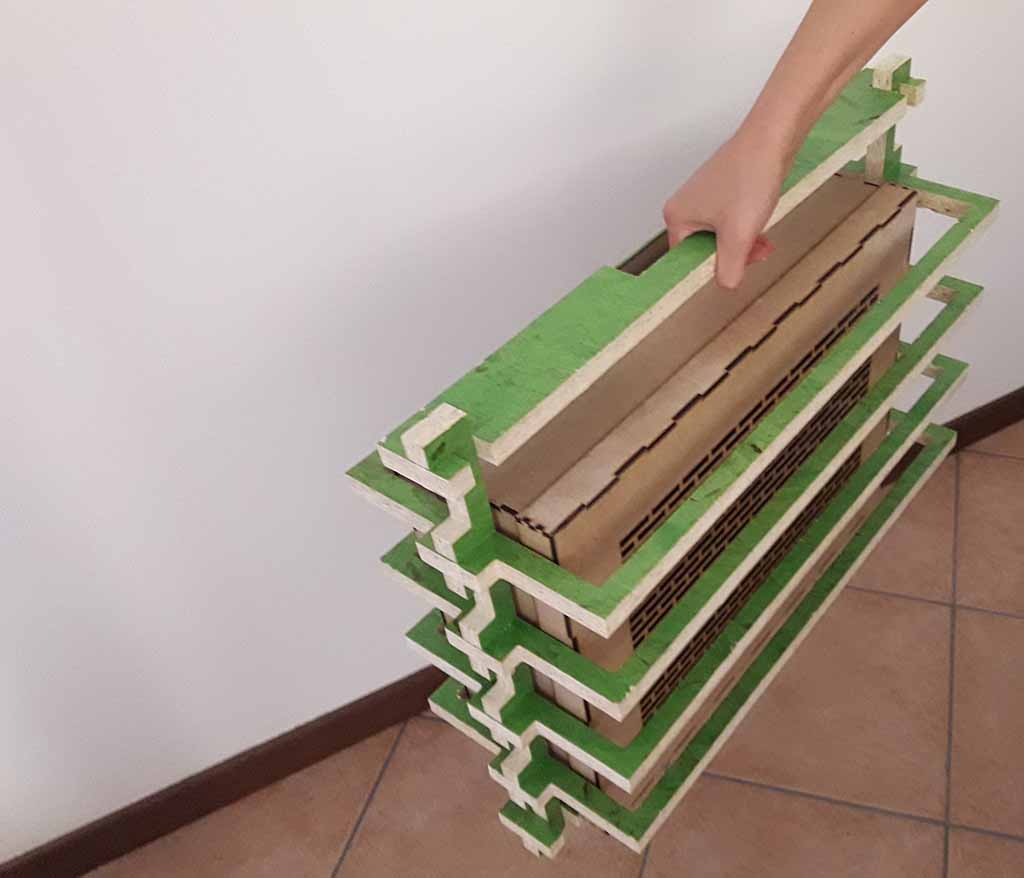
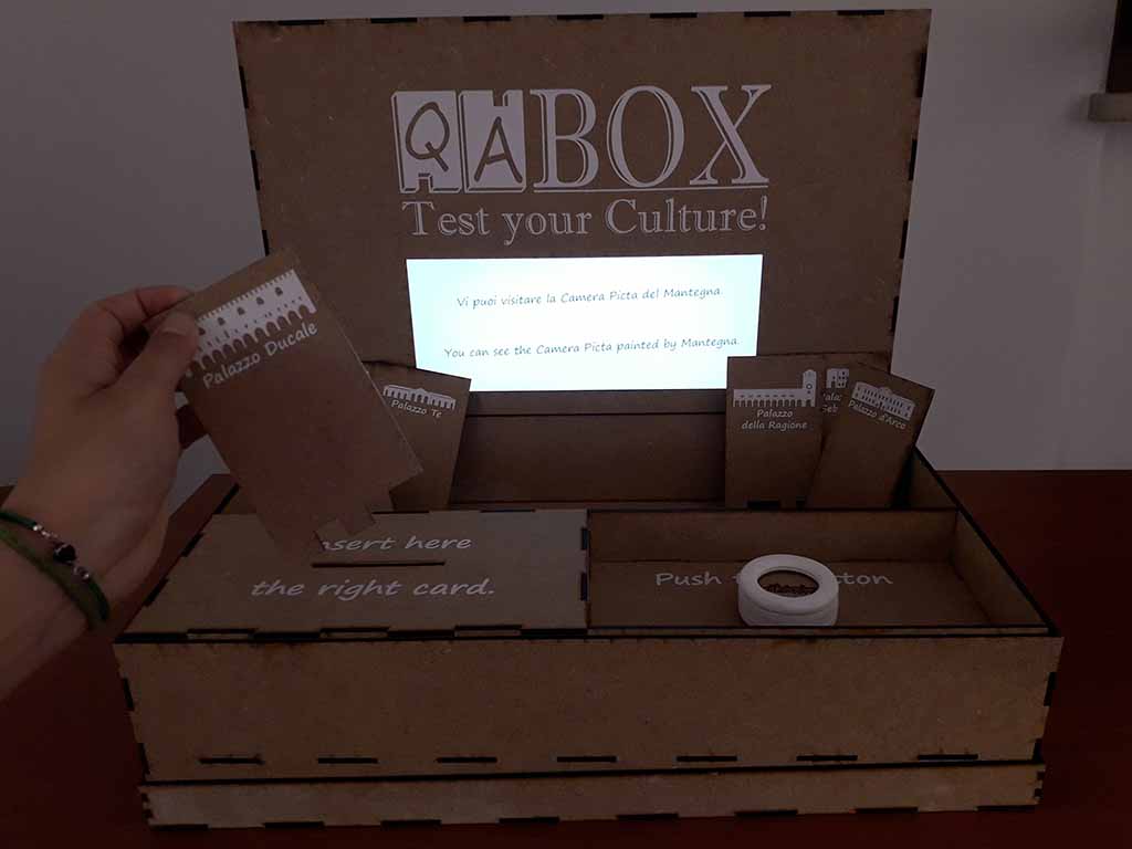
The concept of QA Box is Box to include a notebook, a hole to insert some cards (one for each answer) and a button to start the question. Figure 1 shows this concept. But I wanted to do more, so I decided that the Box could be transported and assembled on site. The notebook could be put inside the closed Box and each part could have to fit in with each other. So I thought these Box pieces:
1. The cover of the closed Box becomes the base to support the notebook (it has a grid for the air);
2. The base of the box becomes the cover for the notebook display;
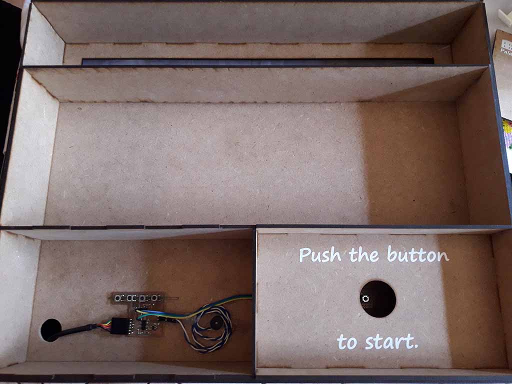
3. The main part of the box covers the notebook keyboard and has three compartments where to put the electronic components, the cards and the button.
You can see these steps in Figure 2.
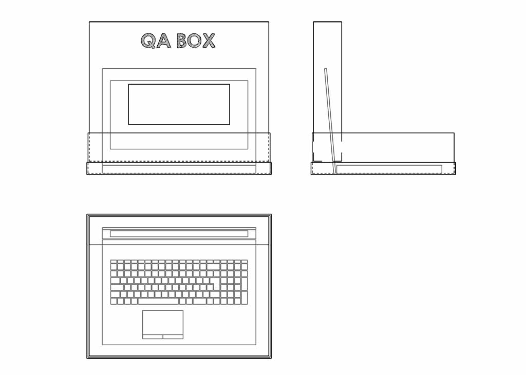
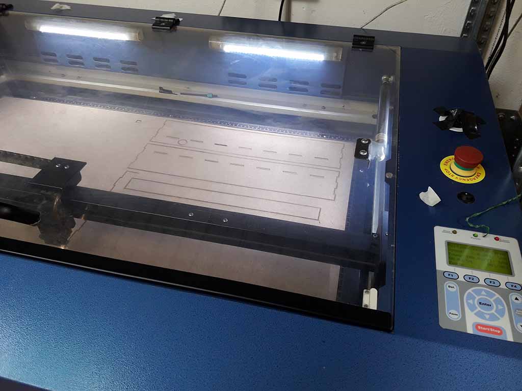
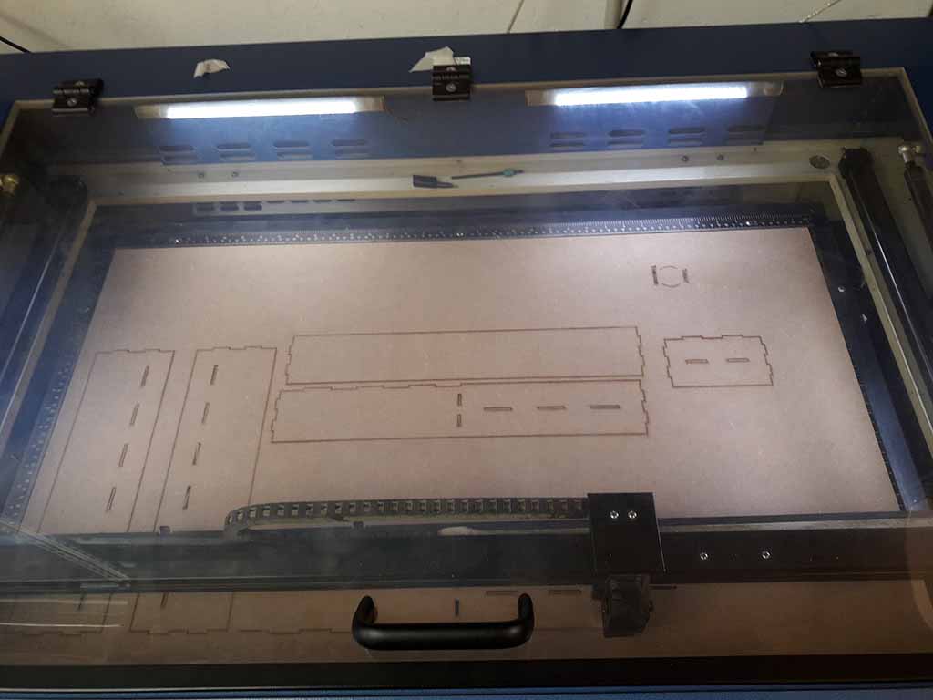
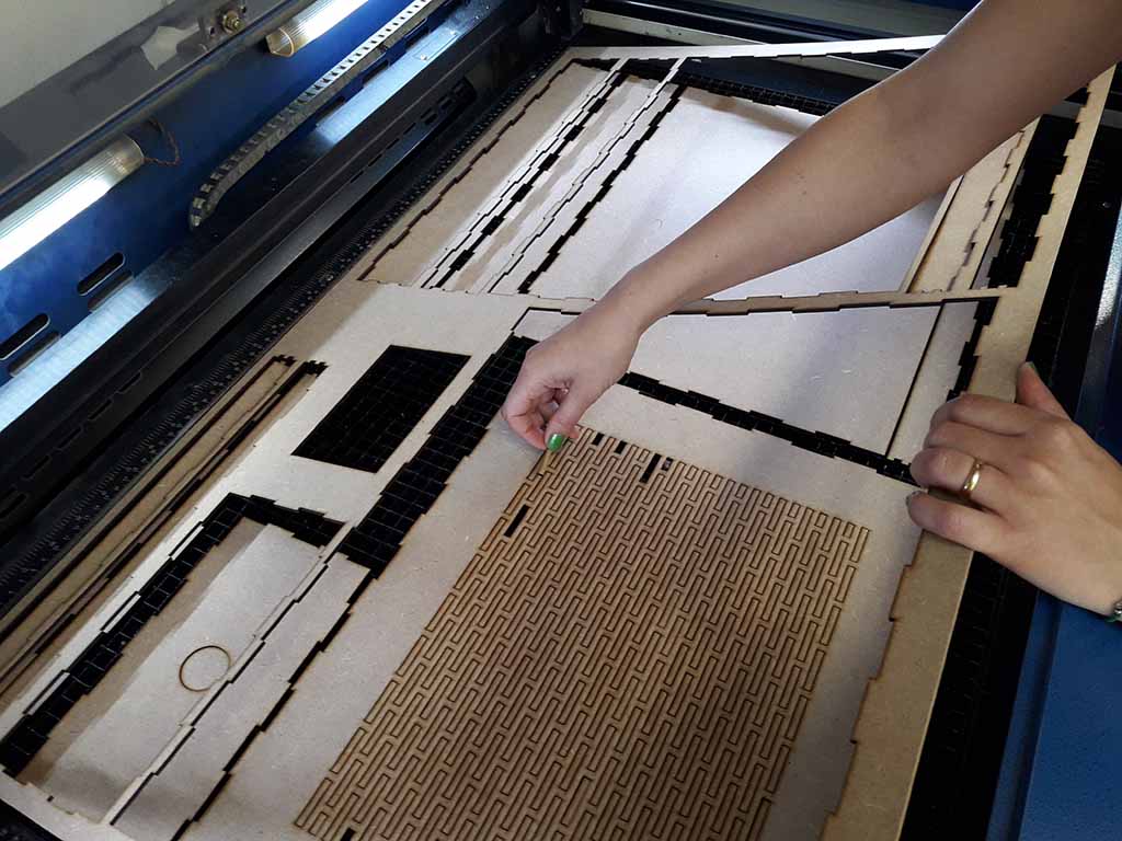
I designed the Box pieces using Autocad (You can download the .dwg file at the bottom of the page) and I laser cut it at Opendot using the GCC SpiritGLS passing through Rhino. To cut the thickness of 3 mm, I used 2,5 for speed and 100 for power. Fortunately I did not have any problems with the laser cutter. In fact, before cutting, I studied the pieces in 3D view and this allowed me to eliminate the errors. To have perfect joints I have increased the thickness of 0.1 mm (the total carve is 0,2 mm). In this way I could assemble the pieces without using glue. Figure 3, 4 and 5 show the laser cutter step. If you want to know more details about laser cutter and How to design through Autocad, you can see my Assignment 3 (Computer-Controlled Cutting).
The Case
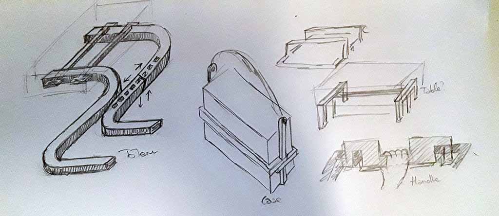
It was more complicated to prepare the Case to carry the Box. I decided to use the CNC machine, but I wanted that the Case could become the Box table. In fact, if the Box is simply putting on a normal table, the base grid becomes useless. Initially I was thinking to make a normal totem, but then I thought about a Case-Table object. You can see my sketches on Figure 6.
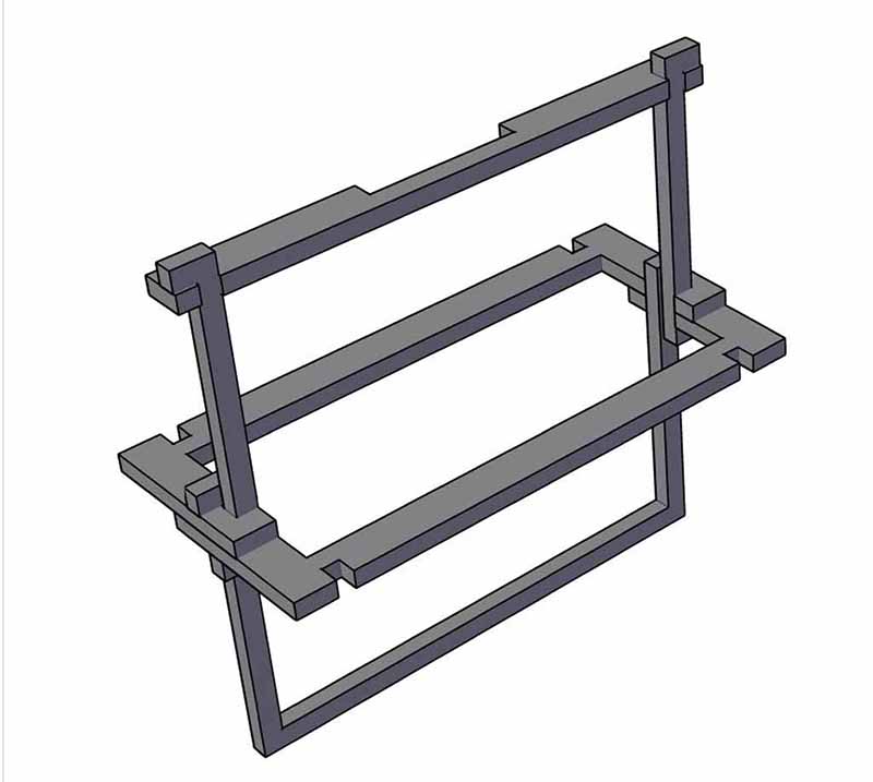
The first version (Fig. 7) was not a success. The four pieces had to be mounted around the box, but then they could not be assembled to form the table. I tried to make a prototype with the 3D printer and I realized that assembly was complicated and the pieces did not stay together easily. After an afternoon of drawings I decided to sleep on.
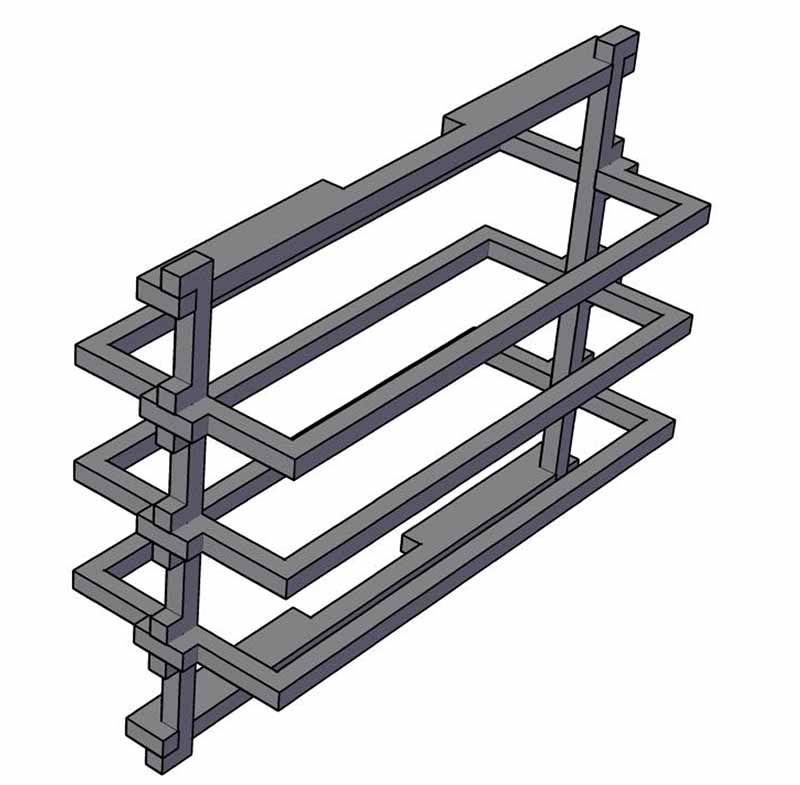
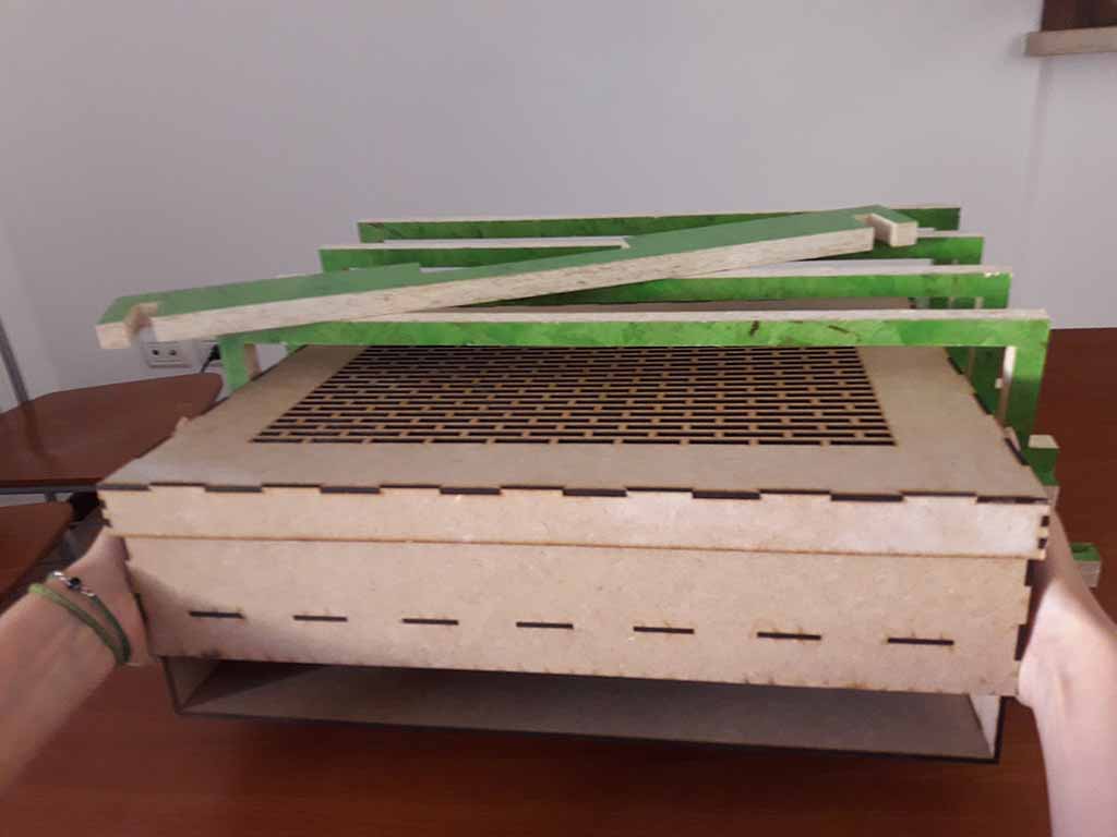
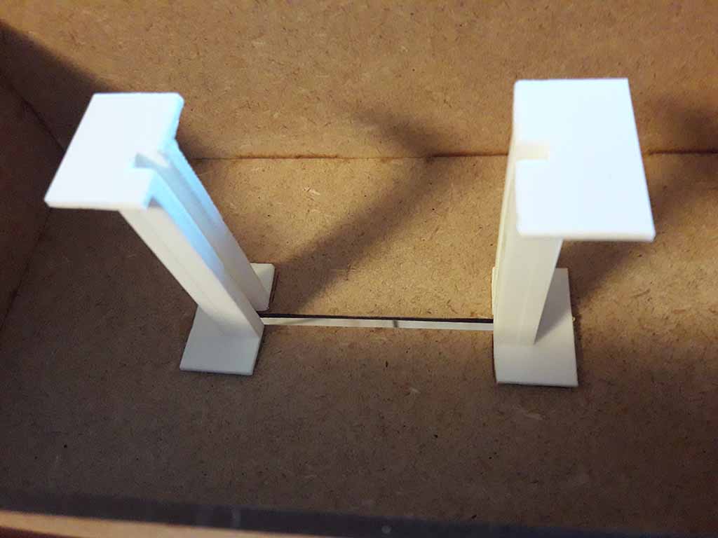
The next day the solution was clear. I designed the final version (Fig. 8) of the Case very quickly: two vertical supports jointed into horizontal cave bases around the Box. I thought to design two types of vertical supports: for three and for four joints.
At Opendot I prepared the file for CNC machine using VCarve and then I moved to the Shopbot. I used the 4 mm tool and I cut the OSB material (Fig. 9 and 10). For details on using VCarve and ShopBot, you can see my Assignment 7 (Computer-Controlled Machining).
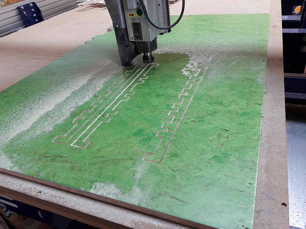
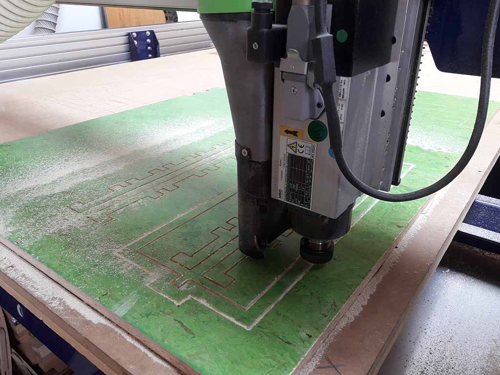
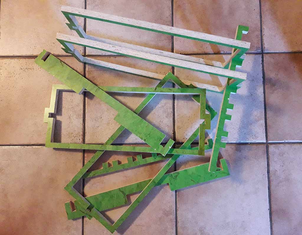
Shopbot took about 40 minutes to finish. Then I cleaned the machine, cut all Tabs and refine all surfaces using sandpaper. Final result was good (Fig. 11) and the Case worked fine (Fig. 12 and 13)!
The Electronic circuit
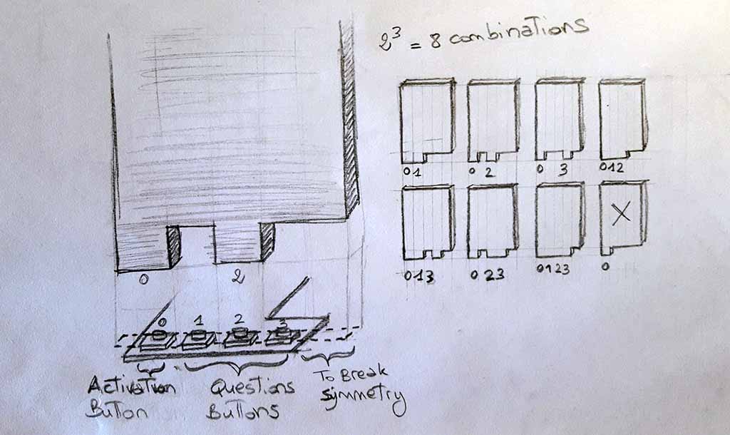
Initially I thought to have four buttons centered on the Card hole to have sixteen combinations. But there was a symmetry problem: the same Card activated two combinations if inserted in both way. To avoid this problem, I thought to put an activation button. But to have only a Card responding to a single combination, I also decentred the four buttons: if the Card space is divides into five parts, you have the activation button at one extreme, one empty space to the other, and the three buttons in the centre. Figure 14 shows this.
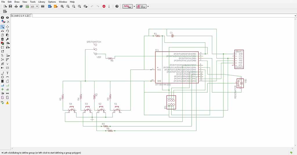
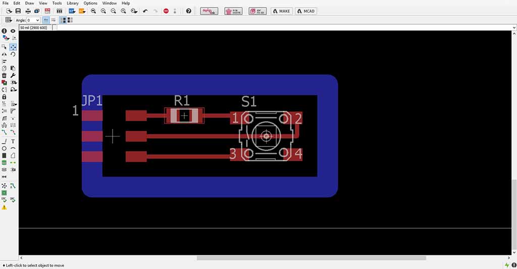
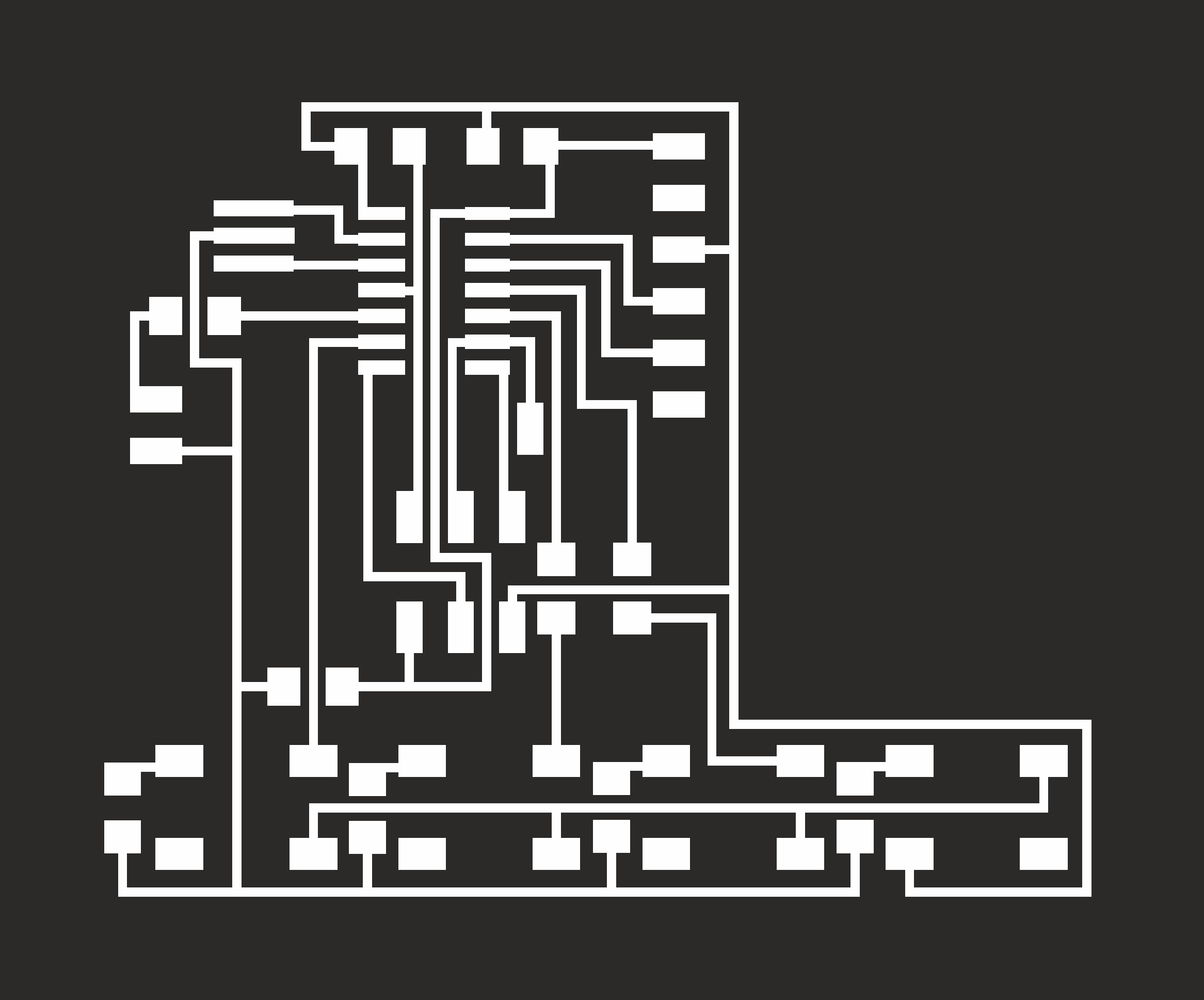
I designed the circuit using Eagle: first the main circuit (Fig. 15), then the circuit for the button that can strat the question (Fig. 16). So I used all the ATtiny44 PINs. I perfected the circuits on CorelDraw (Fig. 17) and prepared the file for the milling machine using the FabModules. I set these parameters on FabModules:
PCB traces (1/64)
- speed (mm/s): 2
- x0 (mm/s): 0
- y0 (mm/s): 0
- z0 (mm/s): 0
- cut depth (mm): 0.1
- tool diameter (mm): 0.4
- n. of offsets: 2
PCB outline (1/32)
- speed (mm/s): 4
- x0 (mm/s): 0
- y0 (mm/s): 0
- z0 (mm/s): 0
- cut depth (mm): 0.75
- stock thickness: 1.5
- tool diameter (mm): 2
- n. of offsets: 1

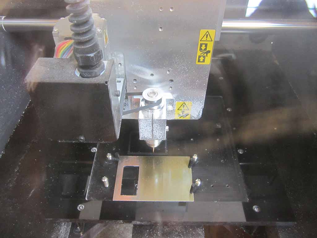
I used Roland MDX-40 (Fig. 18) to mill the circuits at Opendot. If you want to know more details for using Roland MDX-40 you can see my Assignment 4 (Electronic Production). If you want to know more about Eagle you can see my Assignment 6 (Electronic Design).
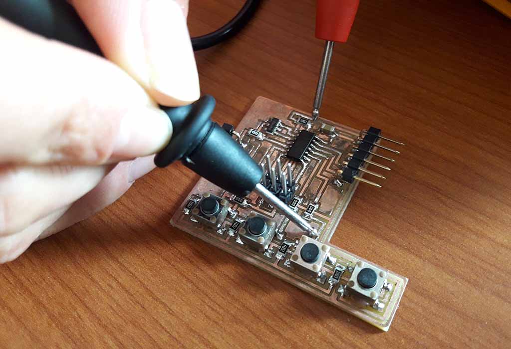
Finally I soldered the components (Fig. 19) and set the fuses (the same of the Hello Board) using my FabISP. Therefore I started to program it. For details about fuses and how to connect the board to the notebook using the FAbISP and the FTDI Cable, you can see my Assignment 8 (Embedded programming) and my Assignment 10 (Output Devices).
The Software
To program the circuit I used Arduino IDE. If you want to know how to install and set Arduino IDE using the ATtiny series, you can see my Assignment 13 (Input Devices).
As I did in the Interface and Application Programming week with Processing, in the Arduino code I decided to use status variable. The status can be: zero if the player press the start button connected to pin A4; one when the ATtiny waits for a new question coming from the serial port; two if it is checking the answer. Specifically, to check the answer the code reads the three buttons of the board (A2, A3 and A7) and computes the combination of pressed and unpressed buttons. So if the combination corresponds to the question, it beeps a positive sound and sends back the value to the Processing interface. Otherwise, it generates a negative sound and waits for the next card. The sound of the buzzer is generated with a sequence of short digital pulses: a "positive" sound feedback comes from a sequence having growing frequencies (DAAA-DI), a "negative" is produced with decreasing frequencies (DI-DAAA). I did not used the piezo speaker library of Arduino because it was too big and the code was to big for the 4 KB of memory of the ATtiny.
Below the code.
    #include

    #define speakerPin PIN_B2
    #define startPin A4
    #define serSpeed 9600

    SoftwareSerial mySerial(PIN_A0, PIN_A1);


    int btn = 0;
    char tanswer = 0;
    int stato = 0;

    void setup() {
    mySerial.begin(serSpeed);
    // mySerial.println("b");
    pinMode(speakerPin, OUTPUT);
    }

    void beep(int delayms){
    for (int i = 0; i < 250; i++) {
    digitalWrite(speakerPin, HIGH);
    delayMicroseconds(delayms);
    digitalWrite(speakerPin, LOW);
    delayMicroseconds(delayms);
    }
    }

    void beepYes() {
    beep(800);
    beep(400);
    }

    void beepNo() {
    beep(400);
    beep(800);
    }

    void loop() {
    if (analogRead(startPin) > 512) {
    mySerial.write(255);
    stato = 1;
    delay(1000);
    }
    if (stato == 1) {
    tanswer = 0;
    int rd = 0;
    while (mySerial.available() > 0) {
    rd = mySerial.read();
    tanswer = rd;
    stato = 2;
    }
    }
    if (stato == 2) {
    int nowbtn = 0;
    if (analogRead(A2) > 512) { nowbtn |= 0x01; }
    if (analogRead(A3) > 512) { nowbtn |= 0x02; }
    if (analogRead(A7) > 512) { nowbtn |= 0x04; }
    if (nowbtn != btn) {
    btn = nowbtn;
    if (btn == tanswer) {
    beepYes();
    mySerial.write(btn);
    stato = 0;
    tanswer = 0;
    btn = 0;
    } else if (btn > 0 and btn != tanswer) {
    beepNo();
    }
    }
    delay(500);
    }
    delay(100);
    }
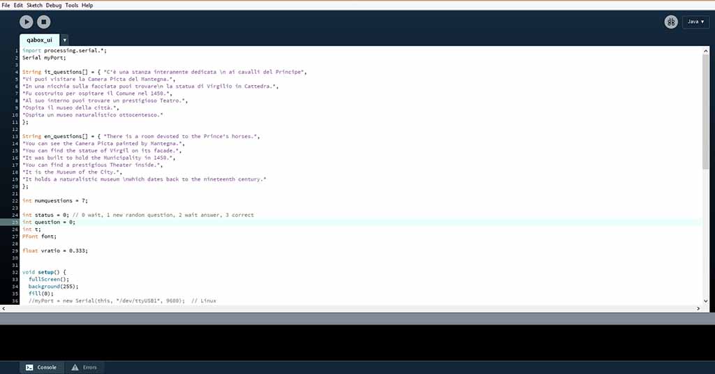
The Processing part (Fig. 20) is better explain in Assignment 16 (Interface and Application Programming). As I wrote above, the combination of pressed and unpressed buttons generates a value that the ATtiny sends through the serial port. The interface reads these value and waits a message from the serial port and when a new byte is received it generates a new question and sends its number to the board.
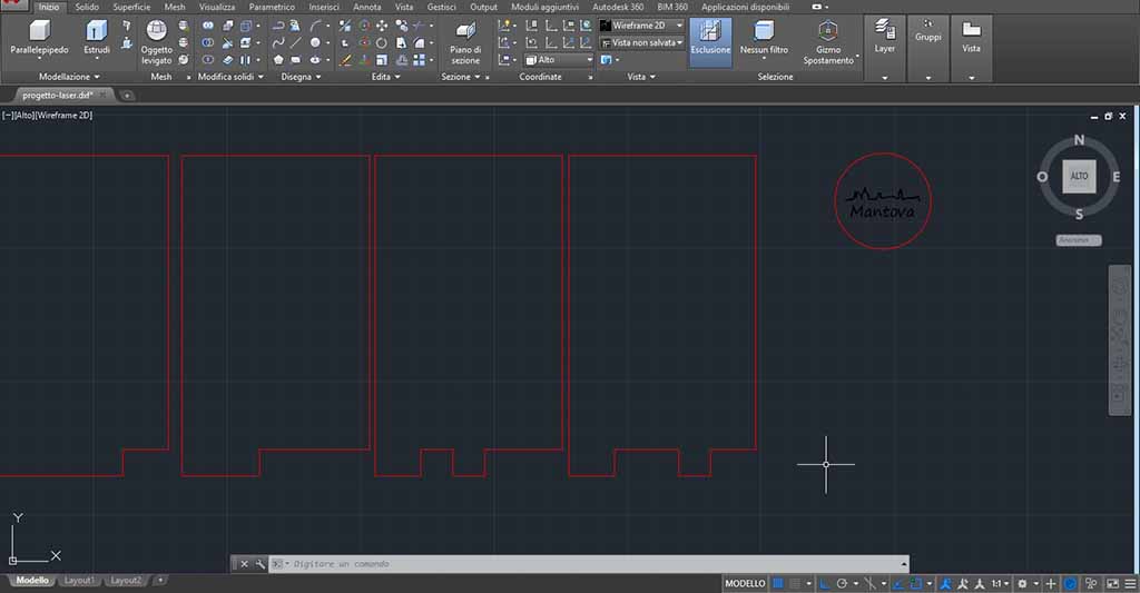
The Cards and the other details
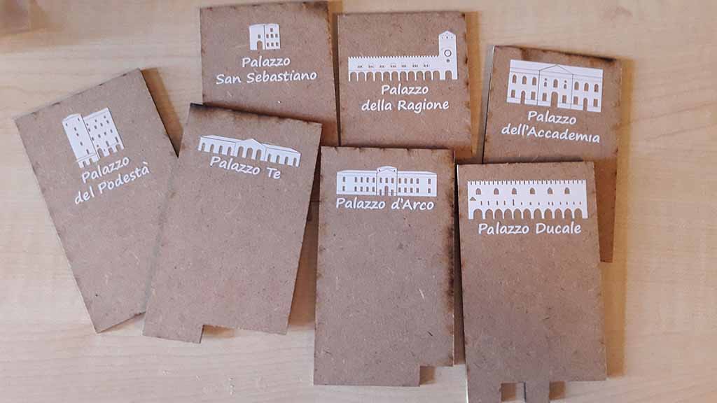
I designed the Cards using Autocad (Fig. 21) and laser cut them using the GCC SpiritGLS again. Together with the Cards I also prepared a circular piece with the topic of the game. I decided to prepare questions and answers about the Mantova palaces, so inside the molded button I put a disk with carved "Mantova" and its skyline. I also laser cut a rectangle of plexiglass to glue it to the Box piece covering the notebook display. I all laser cut pieces into a one .dxf file and you can download it at the bottom of the page. Each cut is a single layer with specified the material. If you want see how I molded and casted the button, you can see my Assignment 12 (Molding and Casting).
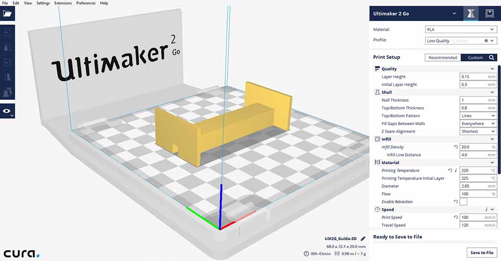
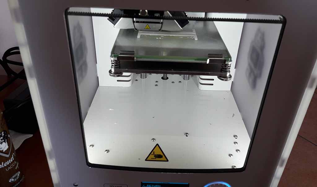
I designed two guide to better insert the Card into the hole. I printed it with 3D printer. I used the Ultimaker 2Go with 0.4 nozzle. To save time I used a layer Height of 0.15 mm and a low Infill of 20% (Fig. 22). I printed the same file two time (Fig. 23). You can see my Assignment 2 (Computer-Aided Design) and my Assignment 5 (3D Scanning and Printing) to know more about 3d design and 3D print.
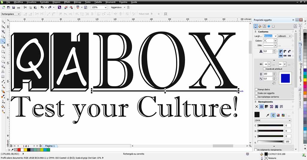
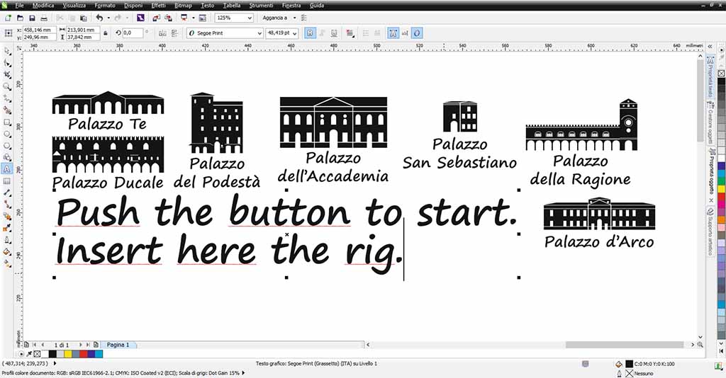
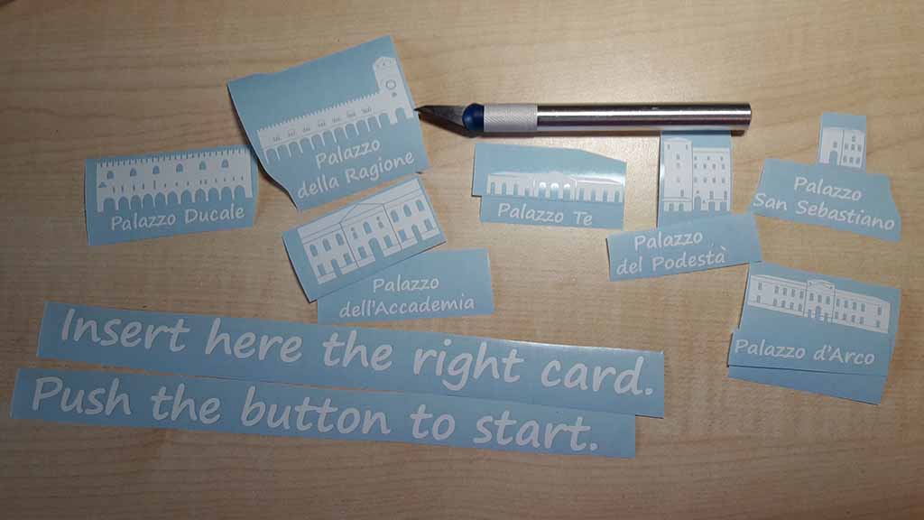
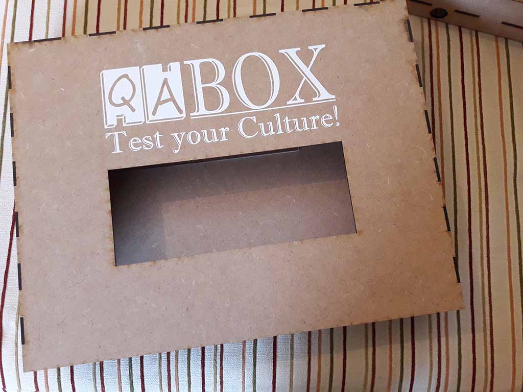
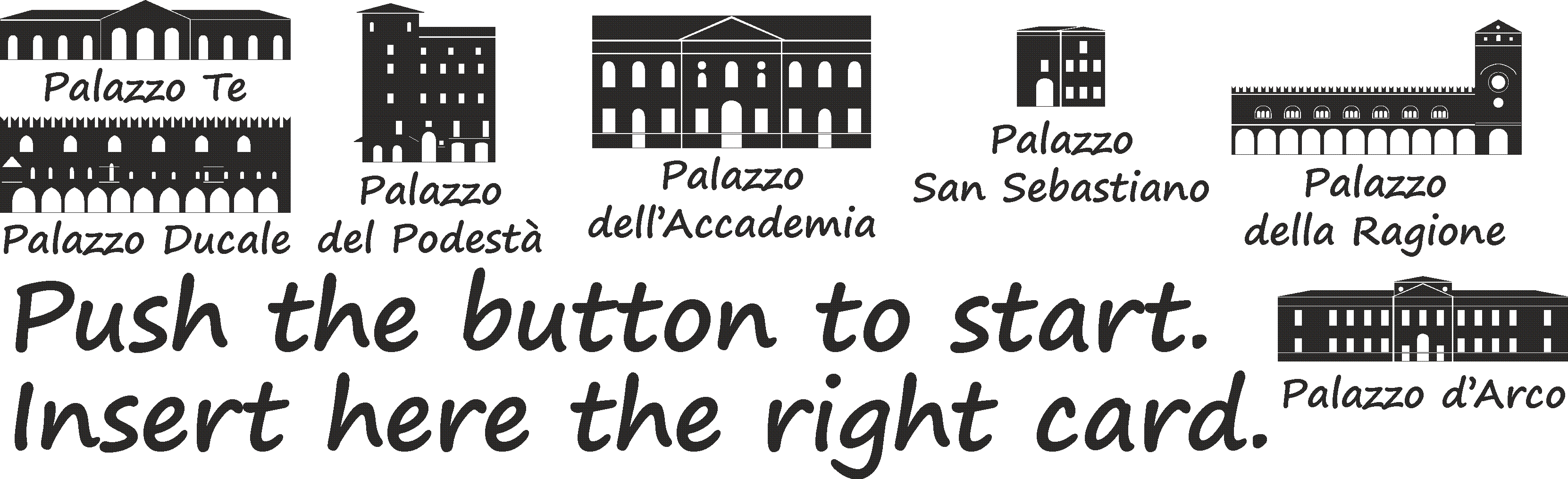
The vinyl cutter part is that I prefer. So I designed on CorelDraw the logo "QA BOX" (Fig. 24) for the front of the Box, some texts and the icons of the single palaces (Fig. 25) for the Cards.
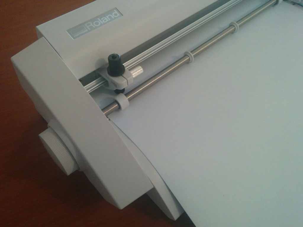
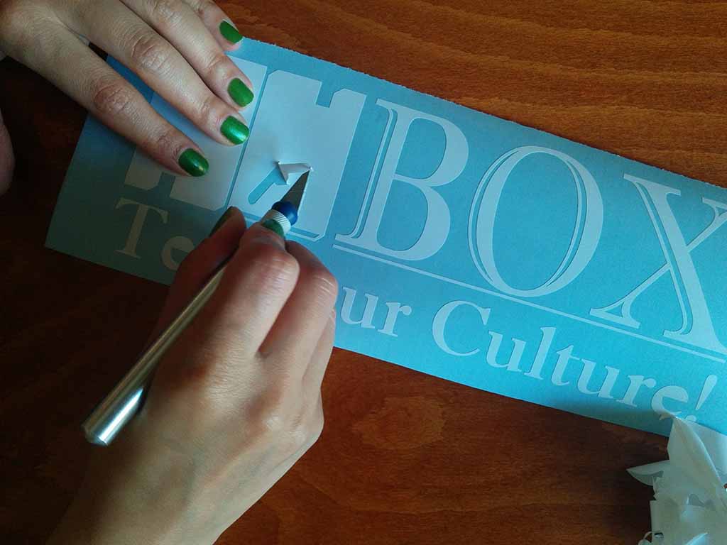
I used a little Roland vinyl cutter called STIKA. I saved the .bmp and .eps format to have more precision.I imported the file on Cut Studio, extracted the contour automatically, inserted the vinyl sheet (Fig. 26) and sent the cut. I weeded the excess vinyl (Fig. 27 and 28) using a cutter. I used a piece of transfer paper to move the drawing to the cover (Fig. 29), the Cards (Fig. 30) and the other pieces of the Box. For more details about vinyl cutter, you can see my Assignment 3 (Computer-Controlled Cutting).
The Assembling
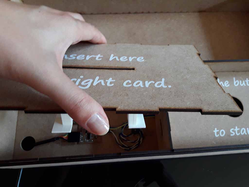
The assembly was easy. First of all I assembled the electronic part on the Box. I fixed the circuits and the cables (Fig. 31) using a bit of hot glue.
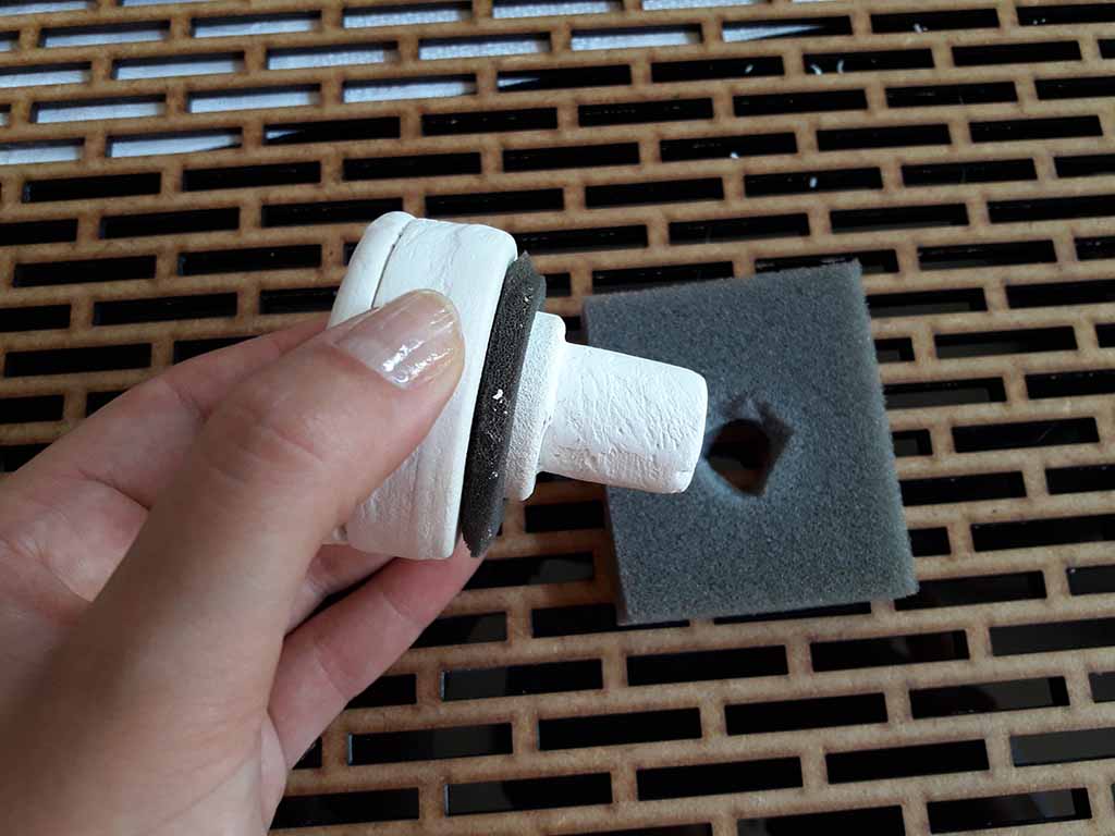
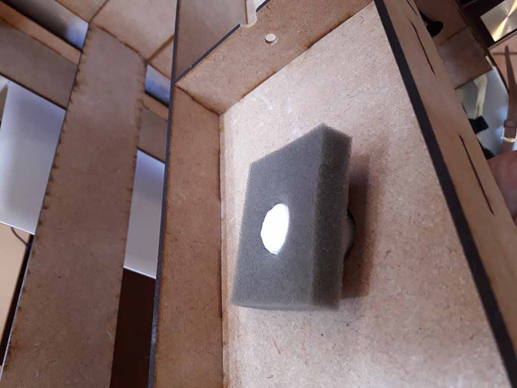
Then I put a piece of sponge around the main button (Fig. 33)to have something like a spring but more soft. I fixed the button at the playwood using another piece of sponge (Fig. 34).
I glued the plexiglass on the cover of the Box and the two guide on the cover with the hole to insert the Card (Fig. 32). Finally I closed the cover for the Card (Fig. 33).
So the QA Box was ready and I started to play (Fig. 37)!
Download area
Download my Case file forthe Shopbot
Download my Main Circuit Schematic Eagle file
Download my Main Circuit Board Eagle file
Download my Main Circuit .png file for traces
Download my Main Circuit .png file for edge
Download my Main Circuit file for milling the traces with Roland MDX-40
Download my Main Circuit for milling the edge with Roland MDX-40
Download my Support Circuit Schematic Eagle file
Download my Support Circuit Board Eagle file
Download my Support Circuit .png file for traces
Download my Support Circuit .png file for edge
Download my Support Circuit file for milling the traces with Roland MDX-40
Download my Support Circuit for milling the edge with Roland MDX-40
Download my 3D file for the guide
Download my .stl file for print the guide
Download my 3D file for the button
Download my file for roughing the button mold using Roland MDX-40
Download my file for finishing the button mold using Roland MDX-40
Download my Corel file for texts and drawings
Download my file for vinyl cut the Logo
Download my file for vinyl cut the texts and the icons