Exercise 12: Molding and Casting
Assignment 12: Design a 3D mold, machine it, and use it to cast parts.
What am I modeling?
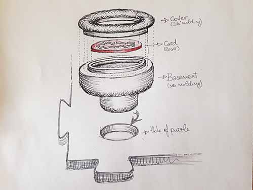
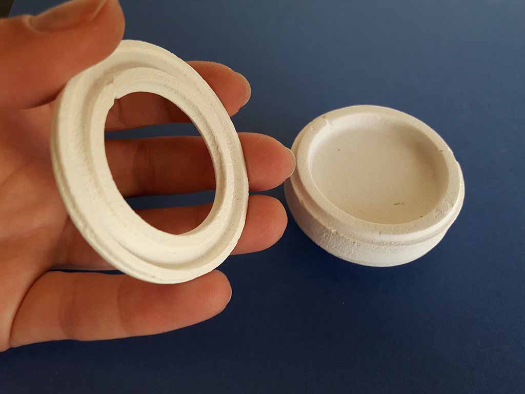
I'm going to draw a 3D object for my final project. It will can put into a puzzle pieces and if the position will be correct something will happen. So this 3D pawns has to have a theme connected to the puzzle piece. I decided to make a standard pawns in wich it is possibile put into a thematic card. Therefore I designed two parts: one for the basement and one for the cover. Between this two parts there will be the card (Fig. 1).
The modeling: first Rhino then Free Cad
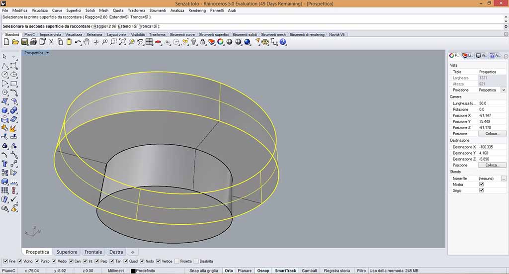
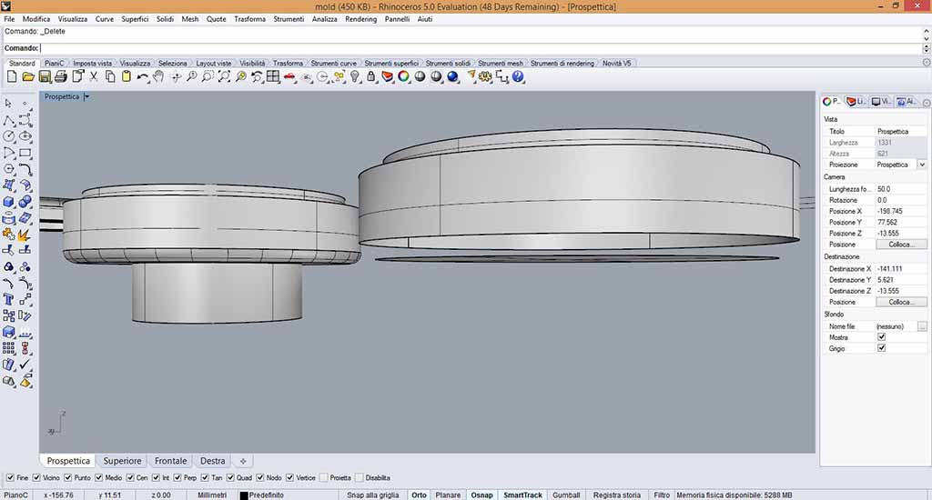
At first I decided to use Rhino (Fig. 2), but after one hour (when I had to draw the smooths to refine the pawns) I saw that "Fillet" command transformed the solids into faces, as you can see in Figure 3. I tried to solve this problem searching tutorials, but finally I decided to change software and to use Free Cad.
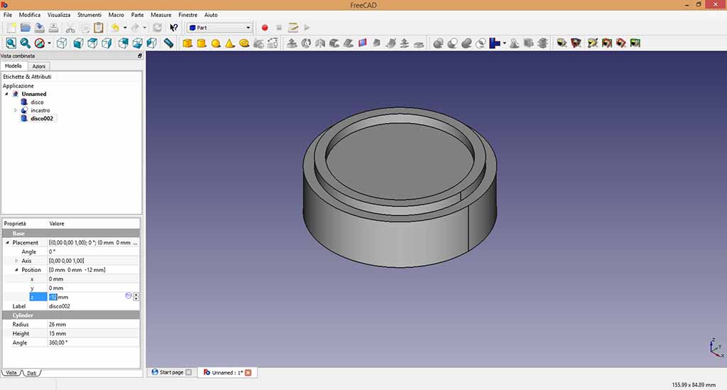
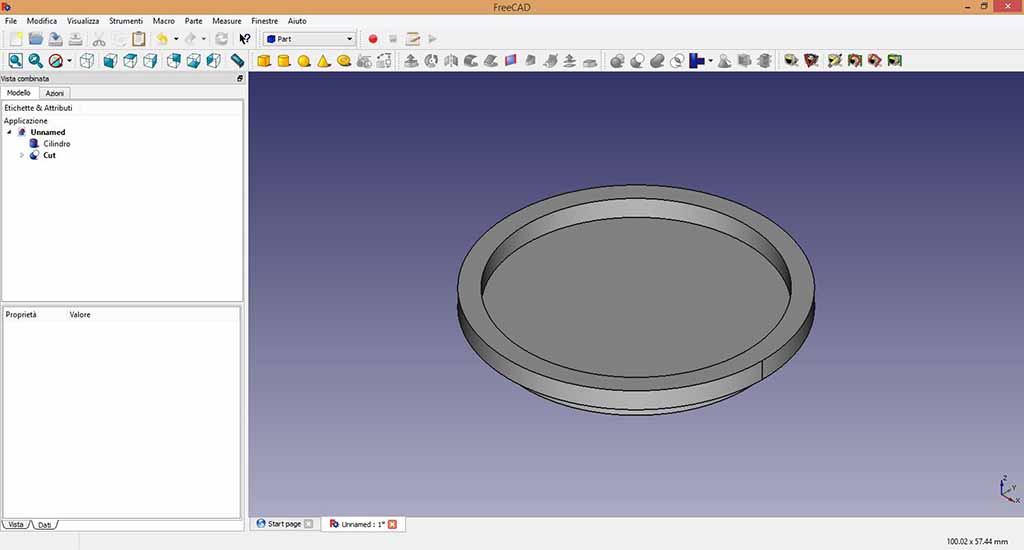
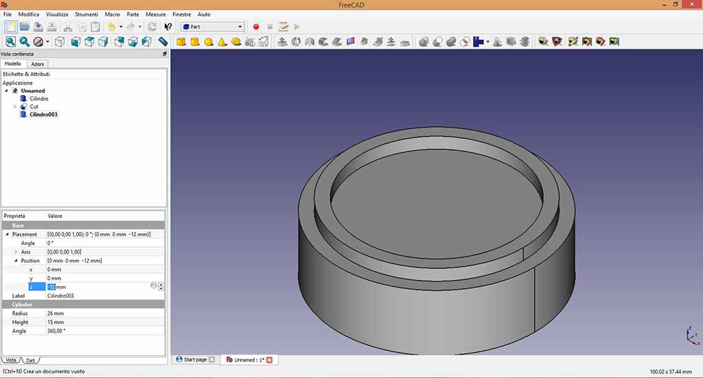
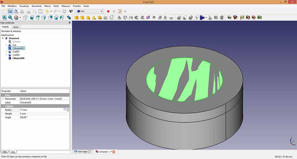
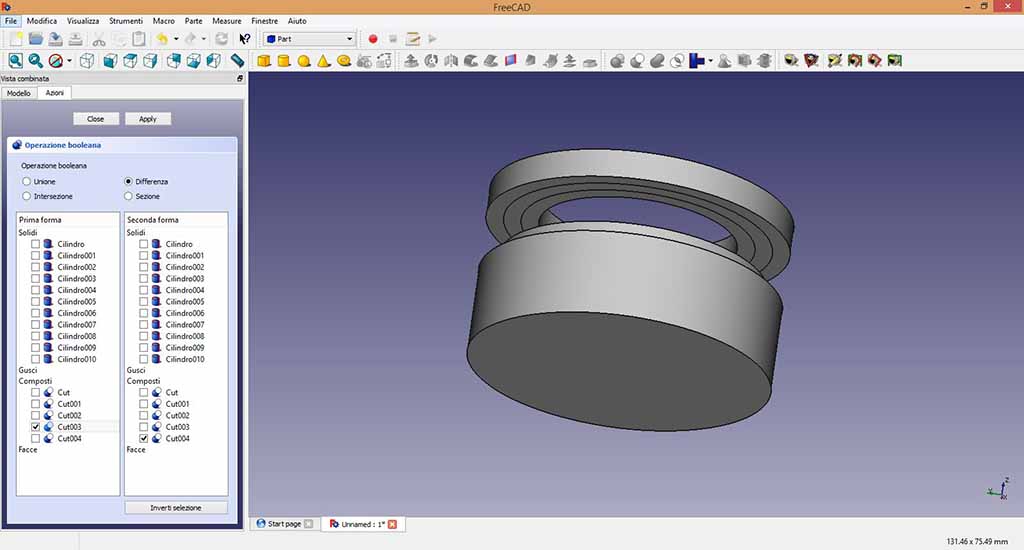
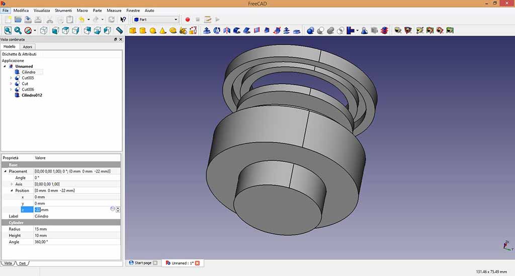
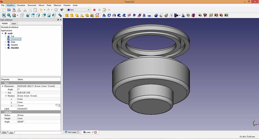
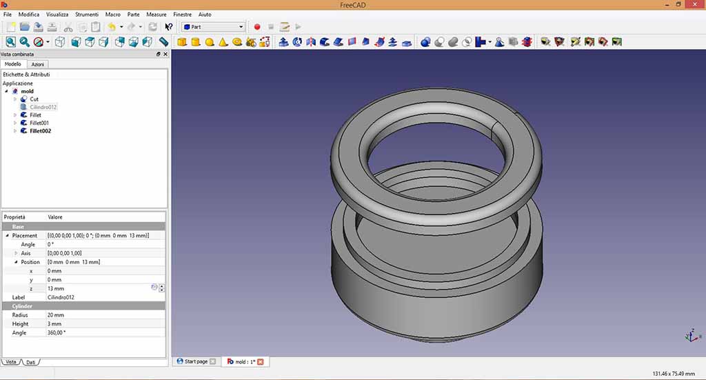
I had not problem using Free Cad: you can see the drawing actions and parameters in Figure from 4 to 12. The drawing is simple: some cylinders added and subtracted. The smooth using FreeCad is simpler than Rhino and after one or two hours I finished the 3D pawns and I could obtain the mold.

 Problem 1: Drawing the mold
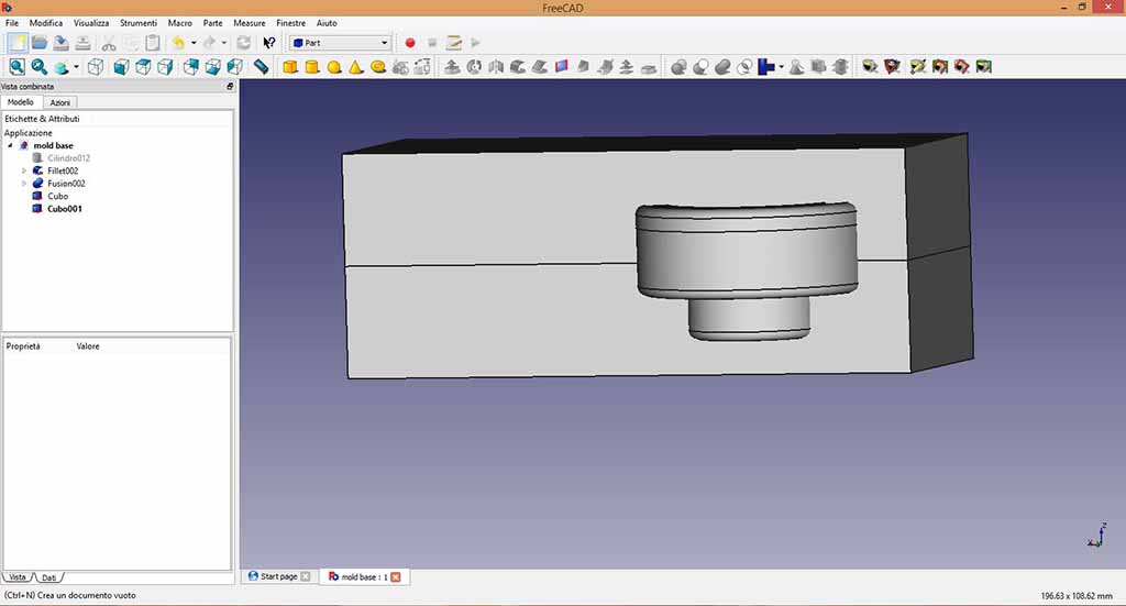
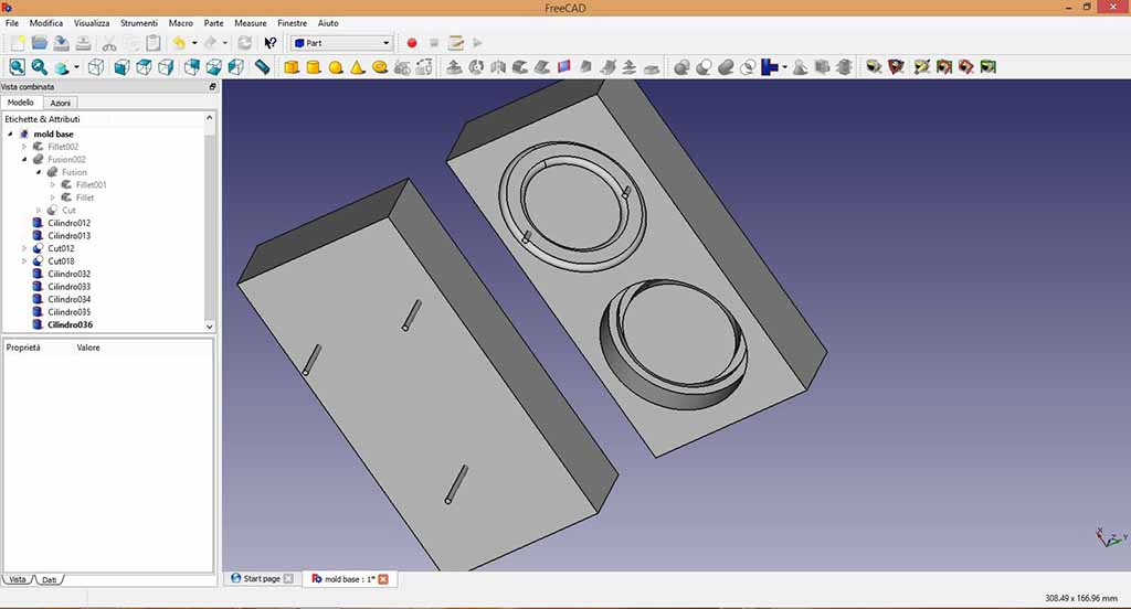
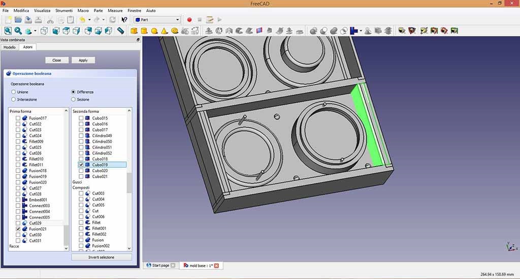
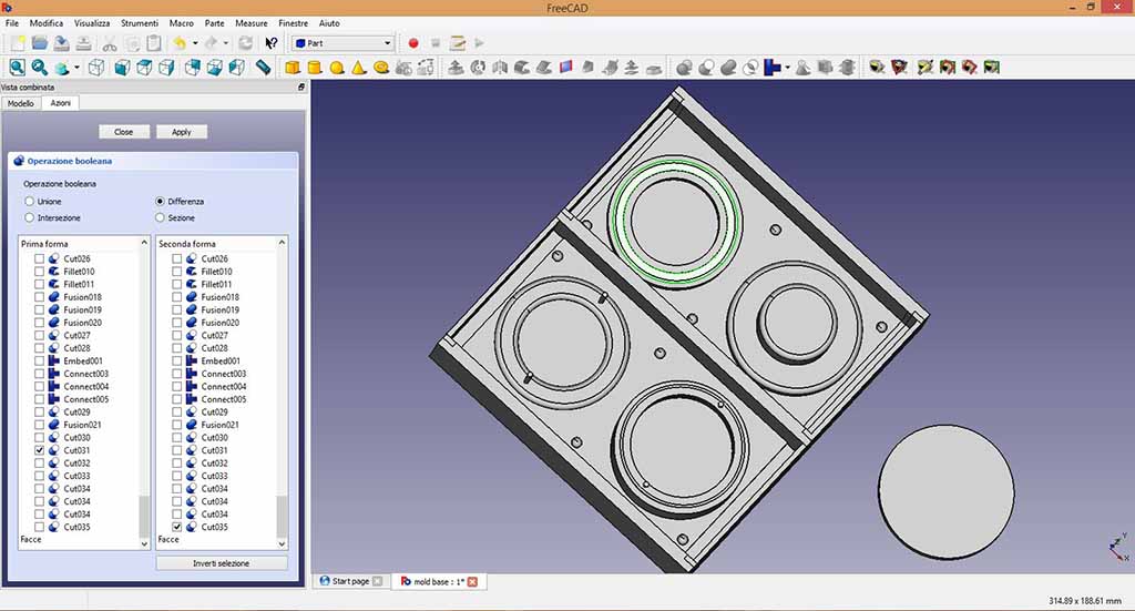
I mistakenly subtracted the 3D I had shaped by a rectangular prism to get the mold (Fig. 13), but I realized there was a mistake because I could not understand how to put the connections to align the two parts of the mold and the cylinders to cast the resin (Fig. 14). So I created another rectangular prism from which I subtracted the wrong one.
Problem 2: Refining the mold
Understanding how to make the 3D model of the mold I managed to draw the connections for mold alignment, but since I was wrong to create the mold the first time, I did not think to preserve the edges to the prism so I designed the edges to get a box where the resin could be cast.(Fig. 14). I could make the edges more higher, but I decided to used a pieces of styrenefoam that I found at Opendot with the same dimensions as my mold.
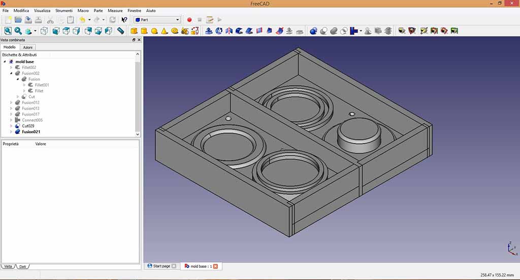
You can show my STL design below.
The milling machine
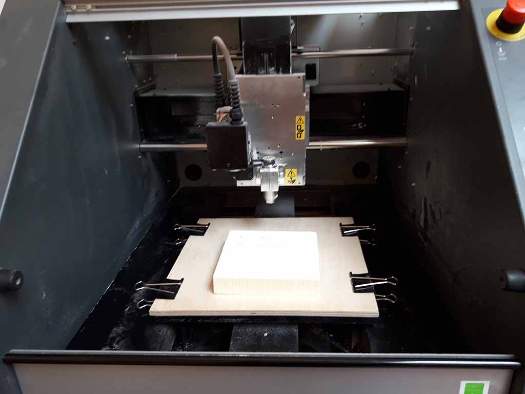
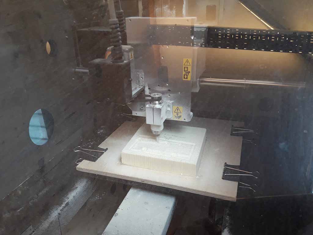
At Opendot I used the Roland MDX-40 machine and SRP Player software. I clamped a wood plate to the machine base and I fixed the styrenefoam to the wood plate using hot glue (Fig. 16).
Problem 3: The model was wrong
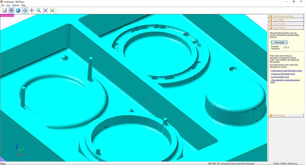
After finishing to prepare the file using SRP Player, I discovered an error. In some parts the endmill could not pass (Fig. 17) so I went back to Free Cad to increase the wrong distances (Fig. 18 and 19).
After exported the .stl file, I returned on SRP Player software and I followed all software step then you can see in the figures below:
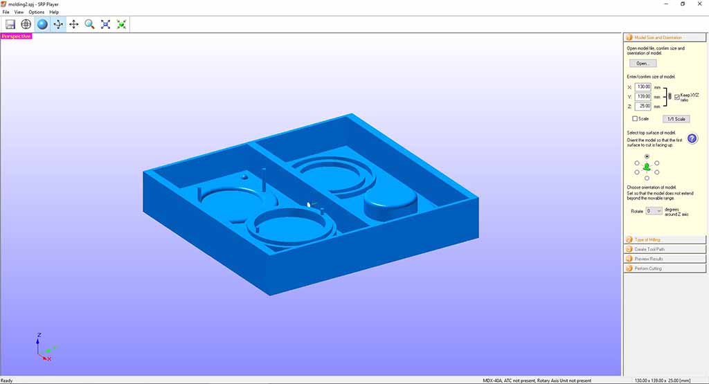
I set up the dimensions of the model in Figure 20;
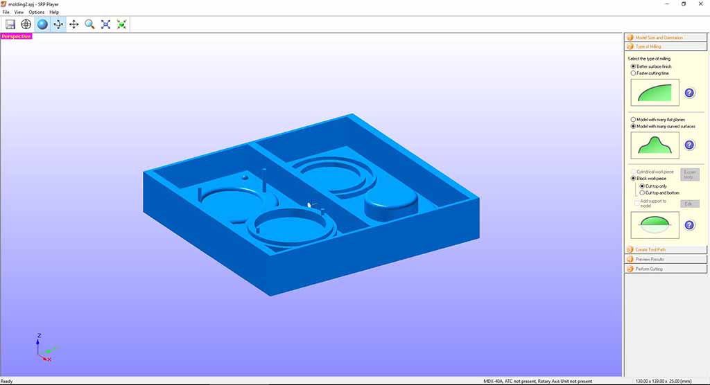
I selected the working of the surface in Figure 21;
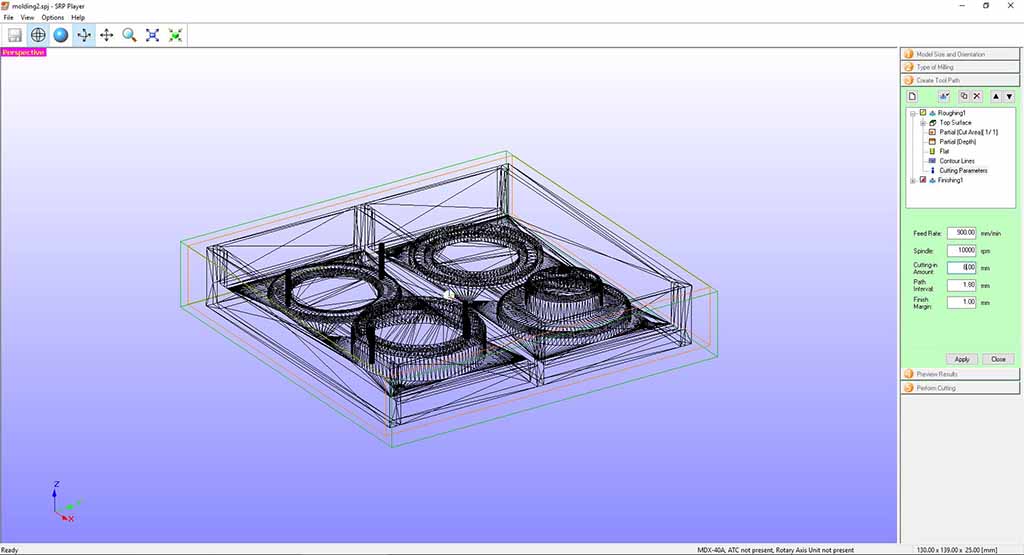
I set up on the "Roughing" window the maximum size of the cutting in Figure 22 and 23,
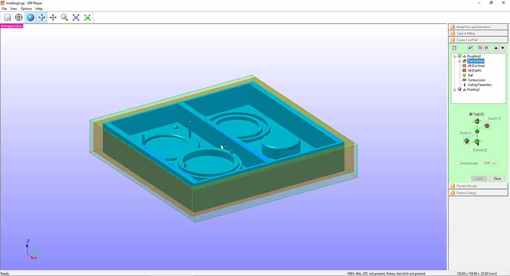
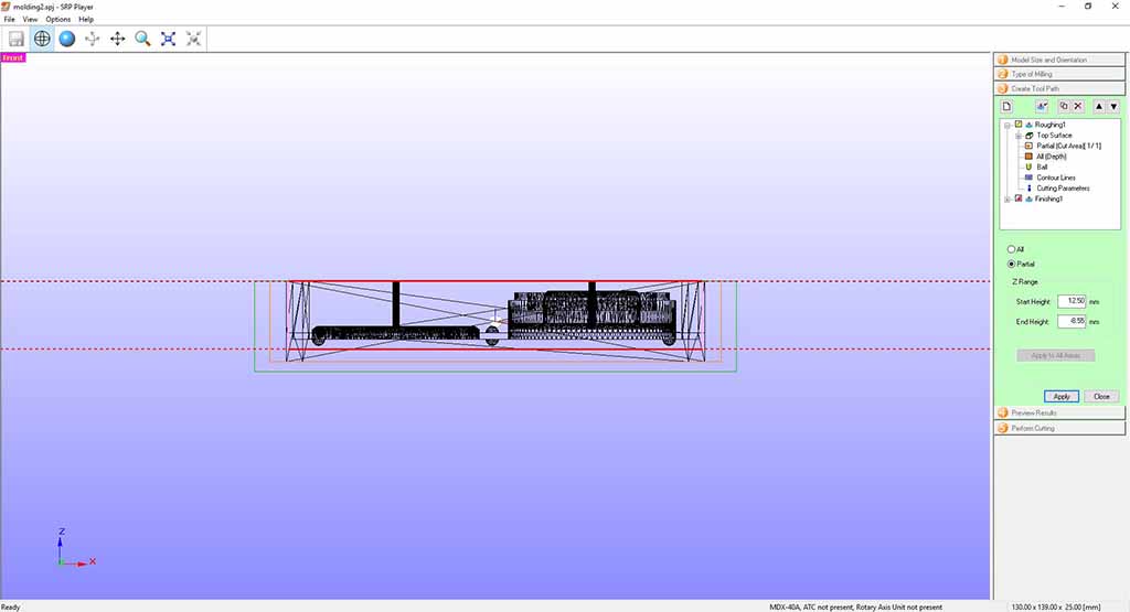
the endmill in Figure 24 and the cutting parameters in Figure 25;

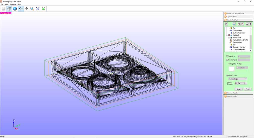
and I did the same on "Finishing" window following all the step (Fig. 26).
Then I chose the material setting Styrenefoam and I created the TooPath (Fig. 27).
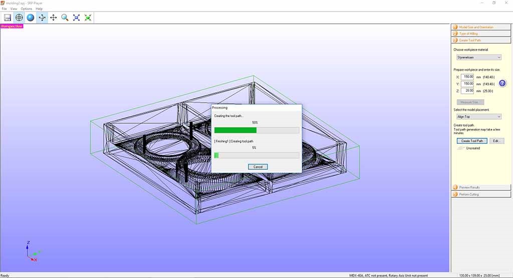
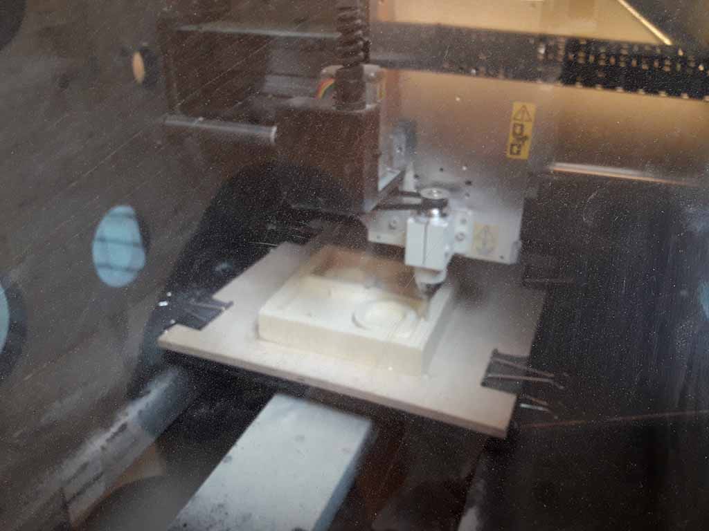
The milling machine started to go the "Roughing" using a 3mm square endmill (Fig. 28) and then the "Finishing" using a 1,5 mm ball endmill (Fig. 29). The process lasted about three hours, but the result was very good (Fig. 30).
The casting phase
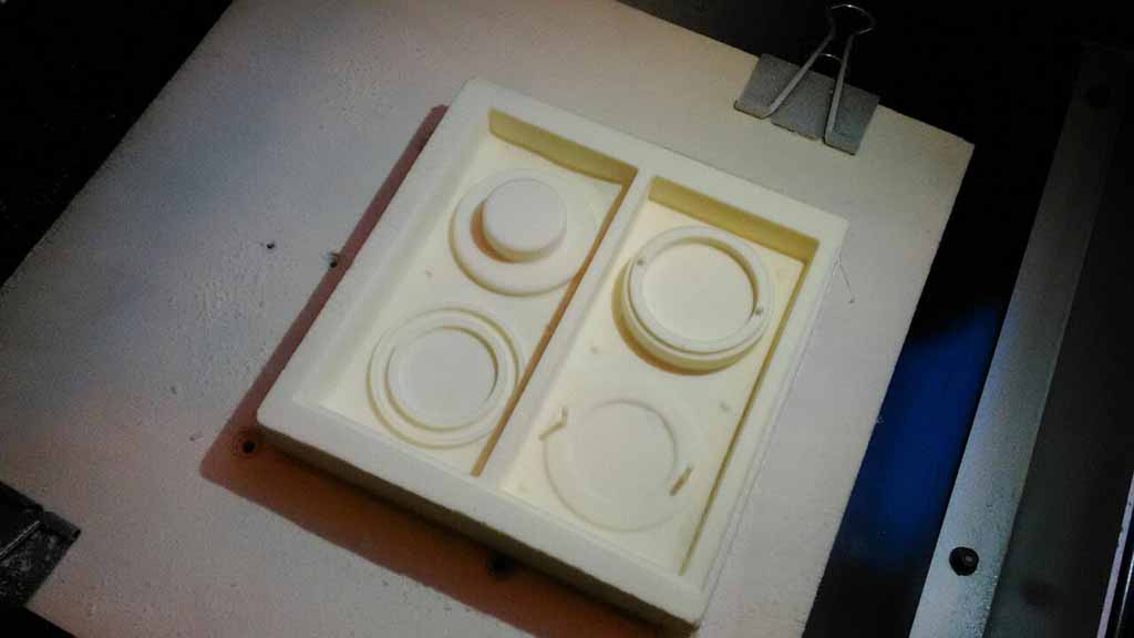
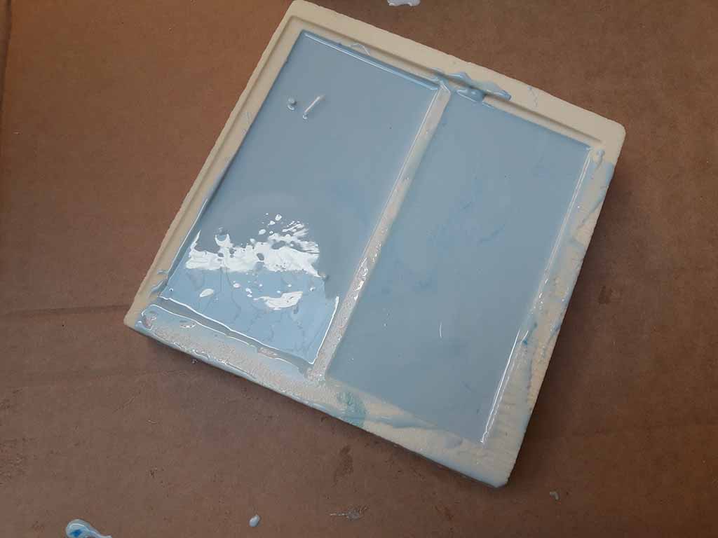
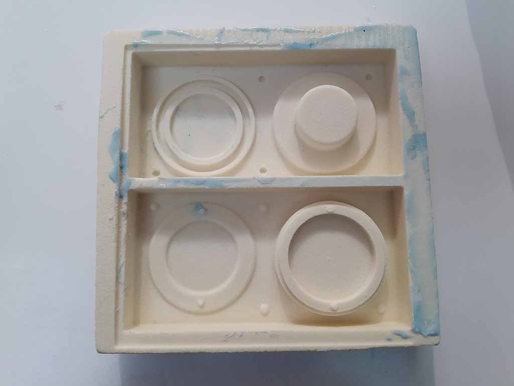
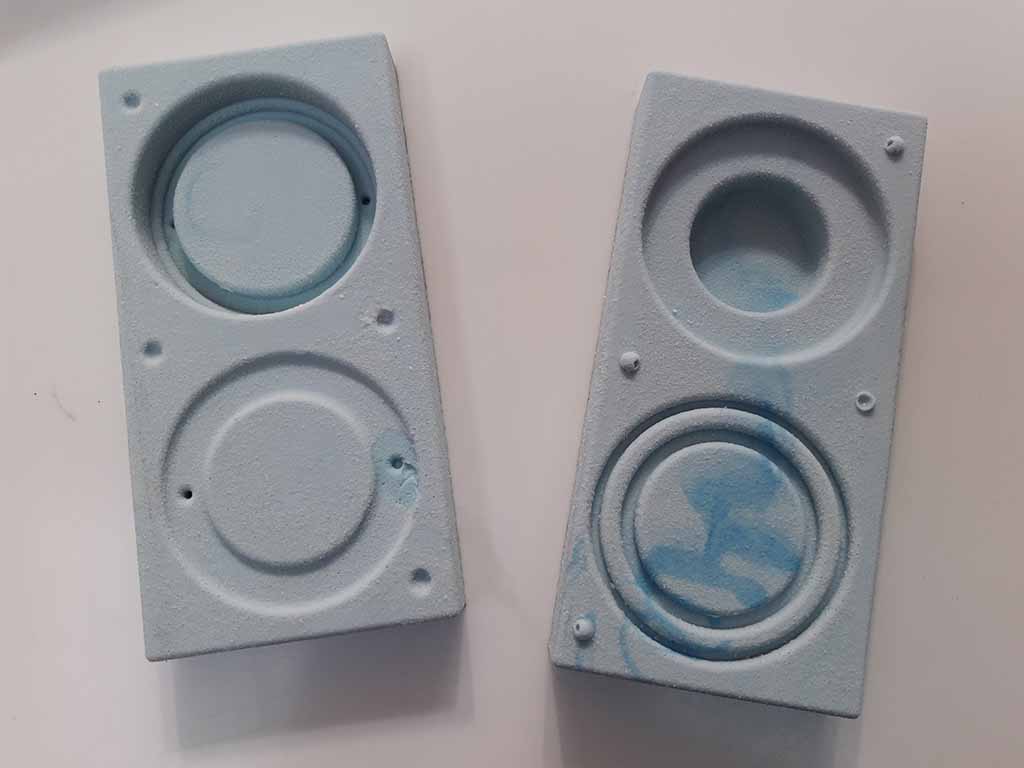
I used a two-component resin available in Opedot to create the mold. I calculated using 3D software that I needed 400 gr of white base component and 20 gr of blue thickener component. I mesured the two components through a weight scale and I blended them until the colors were mixed. It is important to mix slowly to avoid air balls. Finally I cast the resin inside the styrenefoam base dropping the compound from above so that any bubbles could break alone (Fig. 31). I repeated this process two time to have a better result. After two hours the polymerization was finished and I could separate the mold from the styrenefoam. You can see the mold in Figure 33.
 Casting 1: Error with bubbles and material deformation
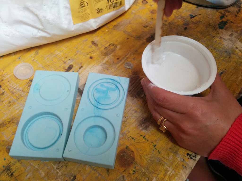
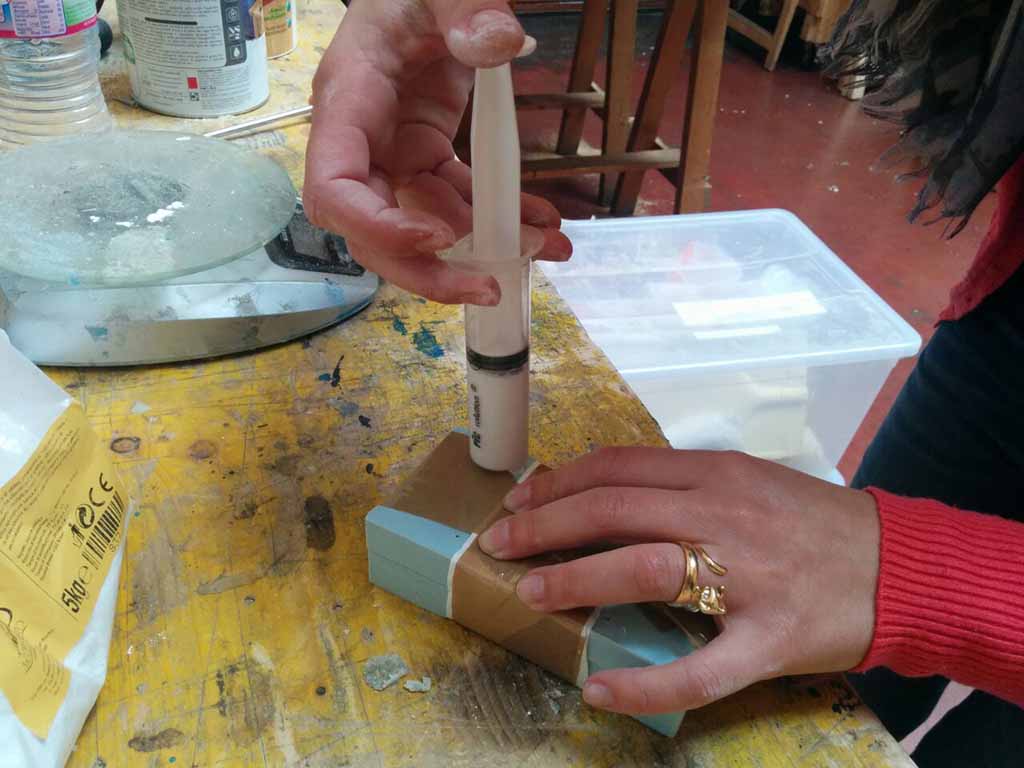
I used the acrilic plaster available at Opendot. The suggested dose was: 300ml of water and 1000mg of material. I mixed them carefully (Fig. 34) and then I used a gun to pour the material into the mold (Fig. 35). I made the casting two times because the first time there were some bubbles and the result was not good. Furthermore, the first time I closed the molds with tape and this deformed the pieces.
 Casting 2: Good!
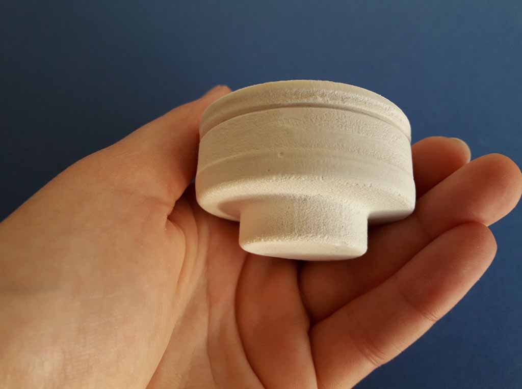
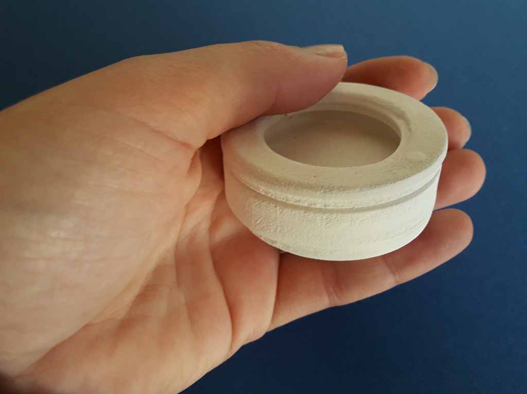
I made again the casting paying more attention and placing a rigid panel above and below to hold rigid the mold. After one hour I opened the mold and the second result was good (Fig. 36, 37, 38). I used sand paper to finish it across the joints.
Eventually I changed my final project but I decided to use my molded object with a different scope. You can find all my final project here.