Exercise 3: Computer-Controlled Cutting
Assignment 3:
- Group assignment: Make lasercutter test part(s), varying cutting settings and slot dimensions.
- Individual assignment: Cut something on the vinylcutter; Design, make, and document a parametric press-fit construction kit, accounting for the lasercutter kerf, which can be assembled in multiple ways.
How to create a parametric design using Autocad
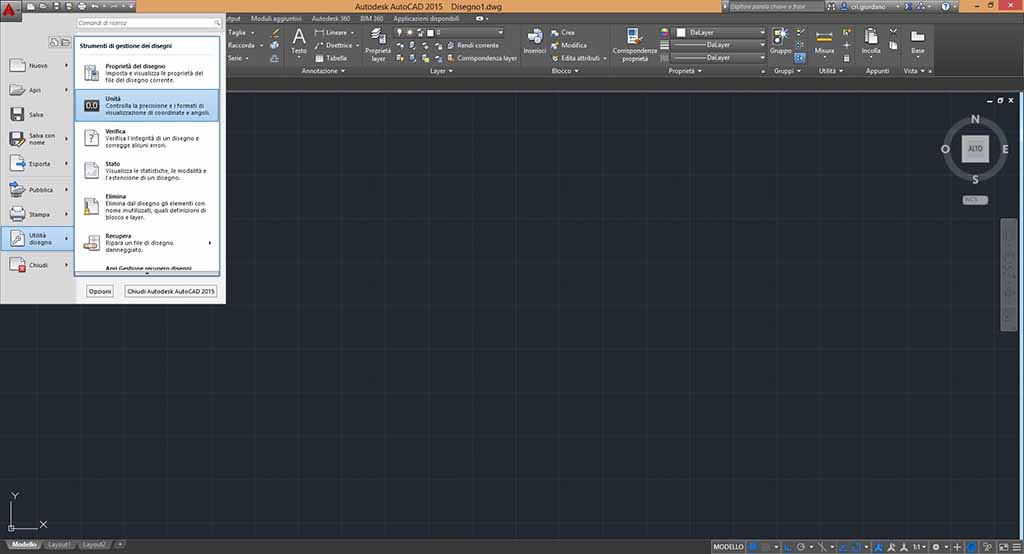
First of all I launched Autocad, opened a new project and set up the unit of measurement (Fig 1). I suggest to use millimetre because the machine works in mm.
Some tutorials suggest to draw an inexact sketch and then to improve it using parametric tools. But this is complicated if you have never used parametric constraint. For example, if I draw two coincident lines and I want to commit that they are perpendicular and parallel to x and y axis, I have to commit two constraint: one to commit that the two lines are perpendicular and one to commit that one line is horizontal. If I use only the perpendicular constraint, it happens like Fig. 2 on the left.
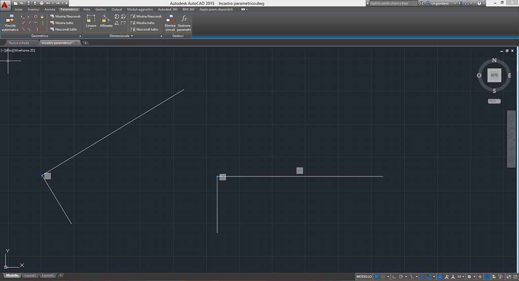
So I suggest to draw as better as you can your drawing before to commit the constraints.
I want to draw puzzle pieces of my final project and I start from the measurement used during exercise 2. If you look at exercise 2, you can find that my puzzle piece has four identical side with two joints for each on them. So I start to draw one of the four side (Fig. 3).
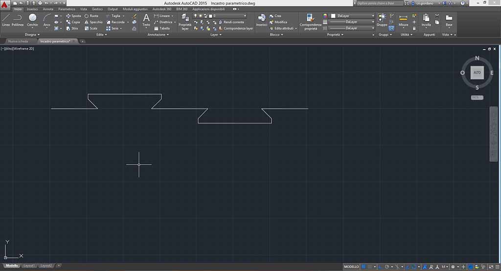
To smooth out the corners I can use “Smooth” like in FreeCad (Fig. 4).
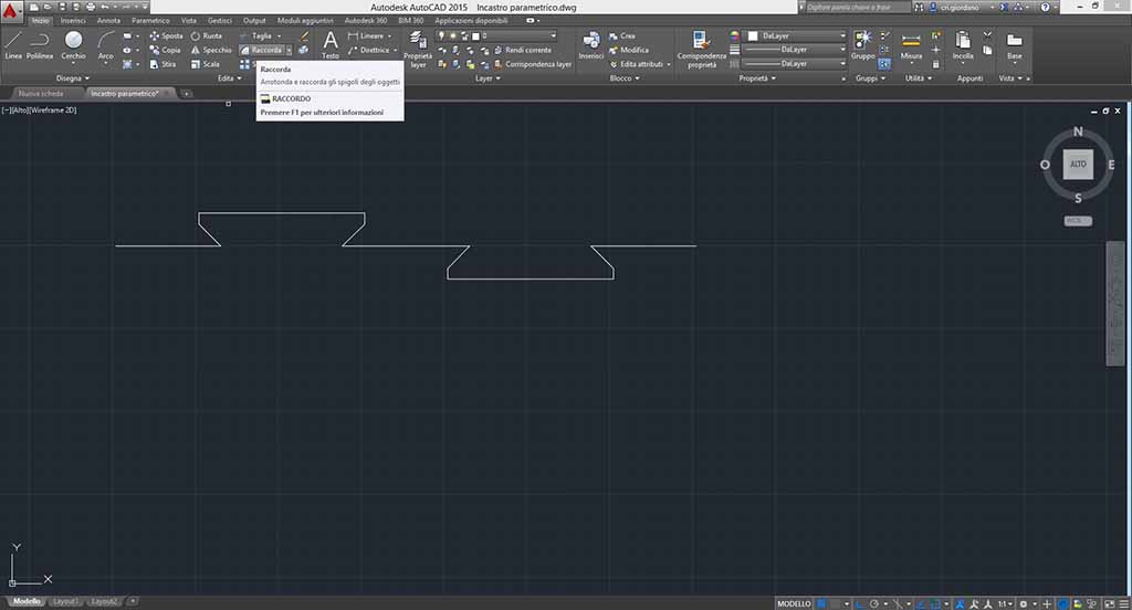
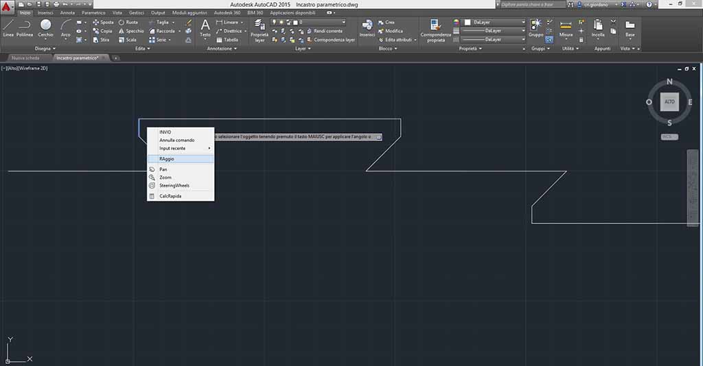
So I choose “Smooth” (in Italian Raccorda), I select the first line, I click on the draw with the right button of the mouse (Fig. 5) to set up the radius (in italian RAggio), then I click on the second line to smooth on.
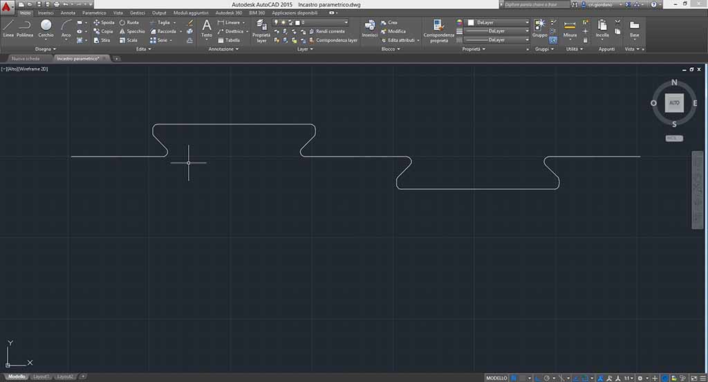
I repeat this operation for every corner using a radius of 2 mm (Fig. 6).
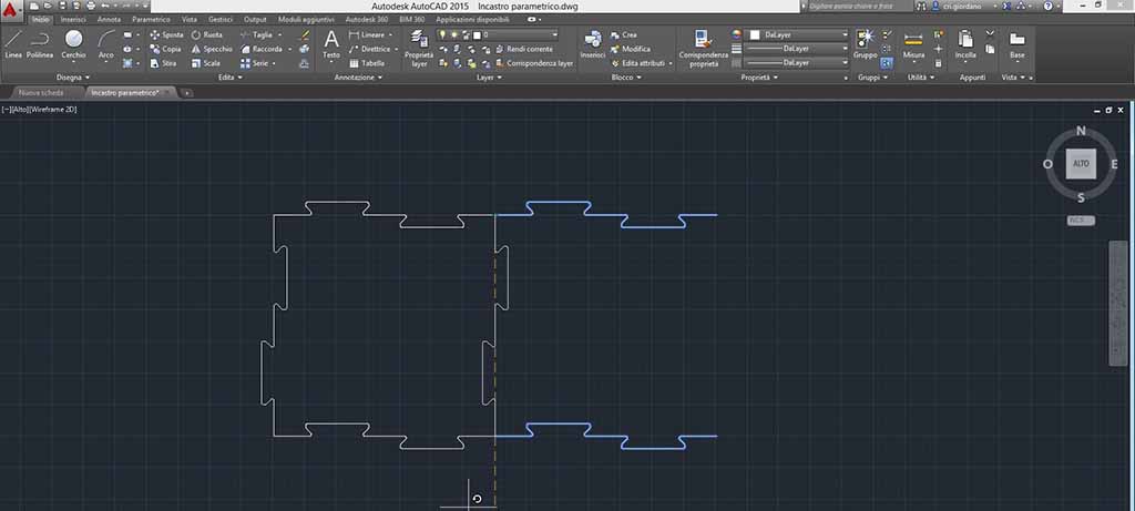
I can repeat this four time or I can use other instruments. I decide to use “Paste” for the other horizontal side: I choose “Paste”, I click on one point of my side and I type 350 mm going down, then I type “Enter” (in Italian Invio). Now I have two sides. To create the perpendicular side, I can paste my two side and the rotate them of 90 degree (Fig. 7).
Now I completed the perimeter of my puzzle piece. How can I commit the constraints? First of all I have to click on parametric window. I can commit two kind of constraints: geometric e measurement.
The geometric constraints are the buttons placed on the left part of the tool bar. I can commit that two or more lines are perpendicular, aligned, parallel, identical, etc. The constraints can be between a circle and a line, two circles, etc.
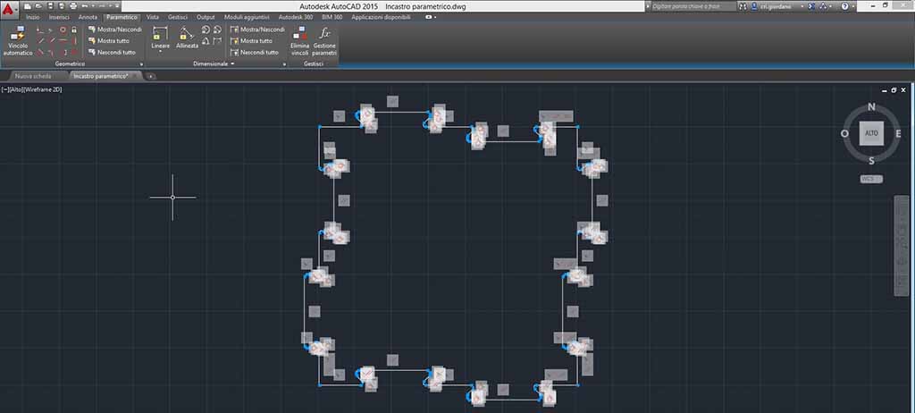
One possibility is to use “Automatic constraint” (in Italian Vincolo automatic). I can use this tool selecting all may draw and click on “Automatic constraint”. The software identifies all geometric constraint like in Figure 8. But it is better to commit the constraints manually because in this way you can understand how your draw can move.
An important constraint is the corresponding: this commit your line to be linked. After this constraint a blue point appears for each point of your draw.
Then I suggest to commit that the four angles measure 90 degrees, so I use perpendicular constraint. Every times that I use a constraint a symbol appears (Fig. 9).

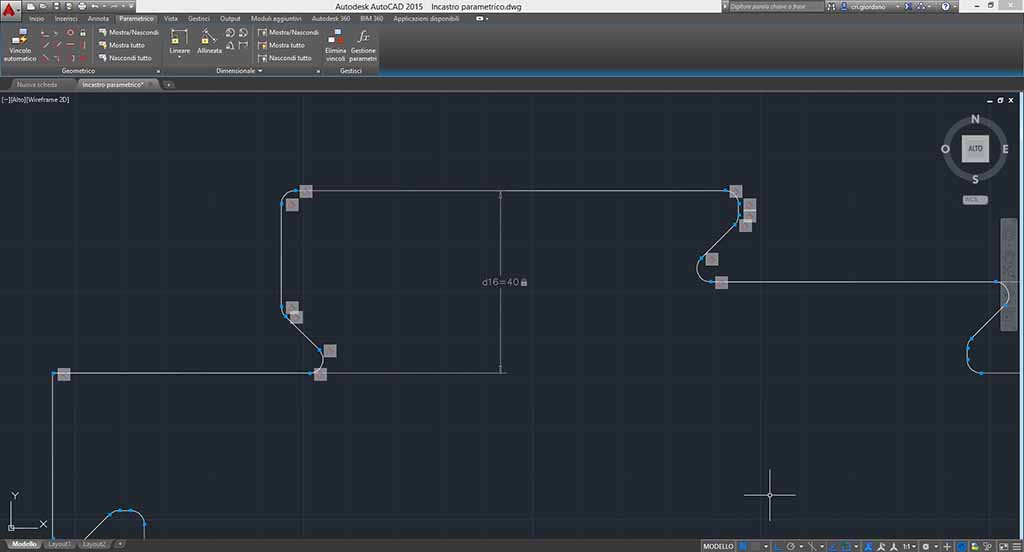
I want to experiment what happens if I change my joints. So I decide to commit only joints height setting up identical measurement for the opposite joints. Measurements constraints are like ranges. I use “Linear” (in Italian Lineare) and I set up the lower and the upper point of a joint, then I type Enter. A range line appear with the possibility to set up the value (Fig 10). To commit that two ranges are the identical value I can set up a value for the first range (for example d1 = 10 mm) and an equivalence for the second (for example d1 = d2).
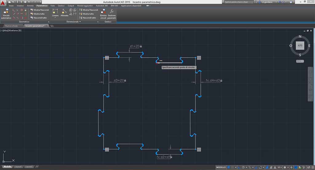
Now my joints are committed and I can try to modify the value. But if I try to modify a value, the joint changes without homogeneity (Fig. 11), so I decide to add constraints.
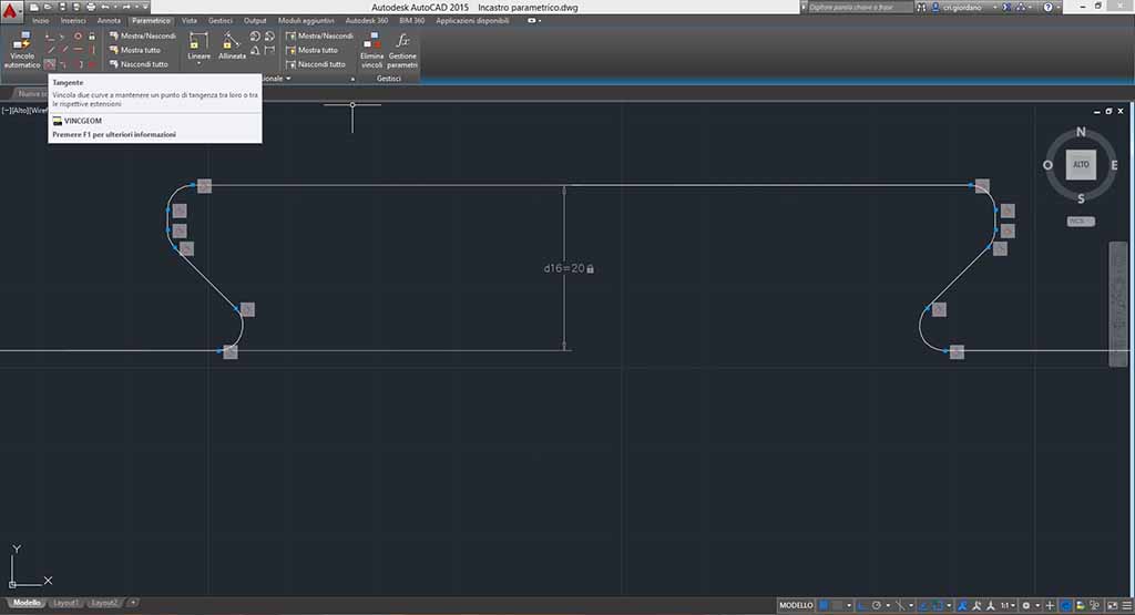
Circle line makes more complicated this drawing and I proceed to commit that every line is tangent to the corresponding circle. If I try to change the value now the circle doesn’t change (Fig. 12). But it is not enough, because my joint doesn’t change equally, so I decide to add that the lines near my joint are aligned.
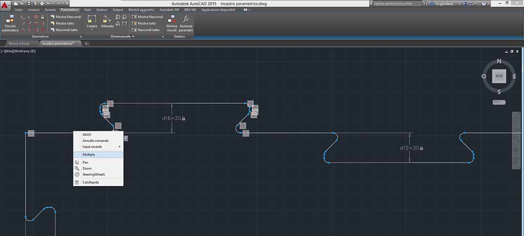
I can select more lines click on “Multiple” (in Italian Multiplo) after choose the instrument (Fig. 13).
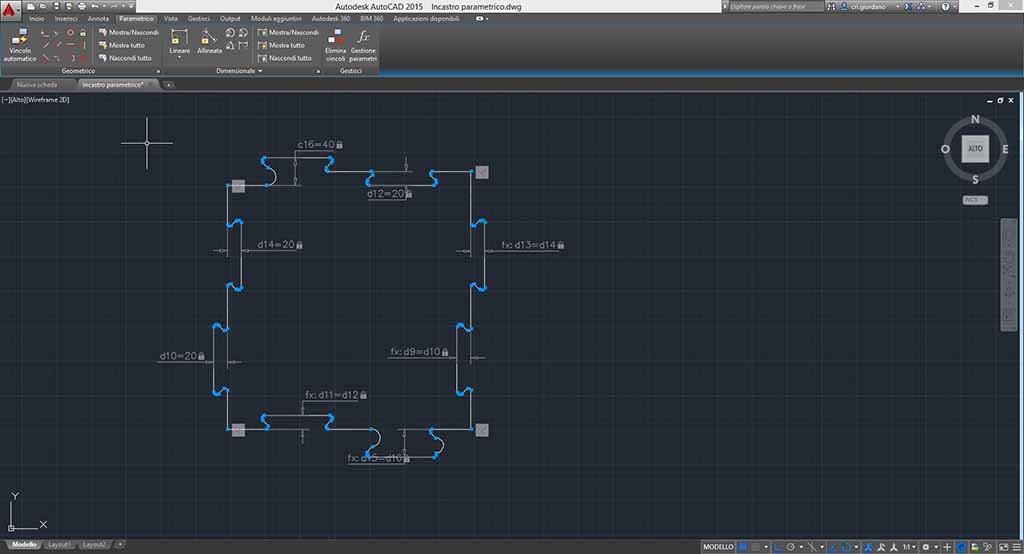
Now changing the value the drawing doesn’t distort. I set up identical value for the opposite joints to force the game. In fact two tracks are inside the puzzle piece, so I want to commit the joints to facilitate the game. But after changing value something wrong happened and some joints are not uniform (Fig. 14).
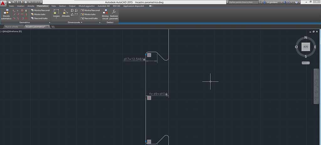
So I have to repair this. First of all I commit that my joint line are horizontal or vertical (it depends on the joint placed) and then I commit the small distance of the joint (Fig. 15).
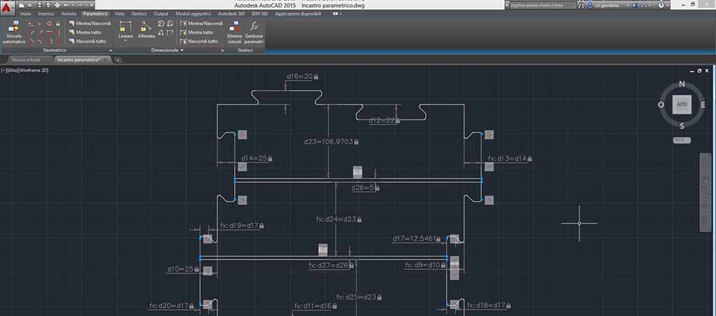
Now I can draw tracks: they are made by two horizontal and parallel lines. I can commit parallel and coincident constraints and set up equal distance from each line (Fig 18). Now, if you try to commit equal width to your puzzle piece the draw becomes crazy. After some attempts I understand that I have to commit the main width of puzzle piece before committing tracks that had a value equal as (main width–2tracks width)/3 (Fig. 16).
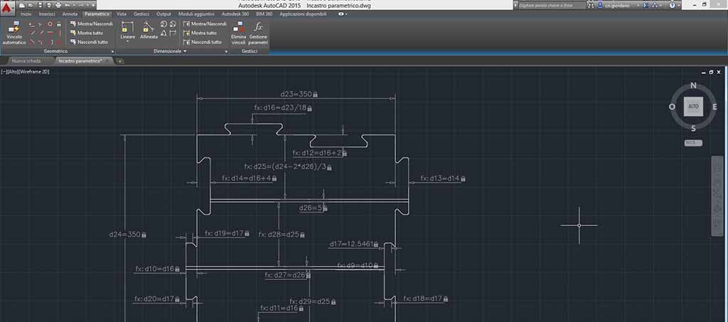
This is an experiment for laser cutter assignment so I want to reduce my puzzle piece, but before I have to commit my joints height to the main width (Fig. 17). I set up 100 mm as the main width.
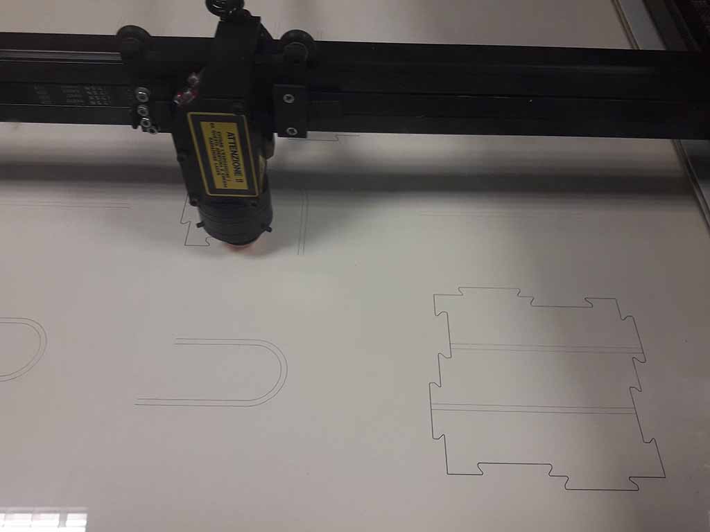
How to use the laser cutter
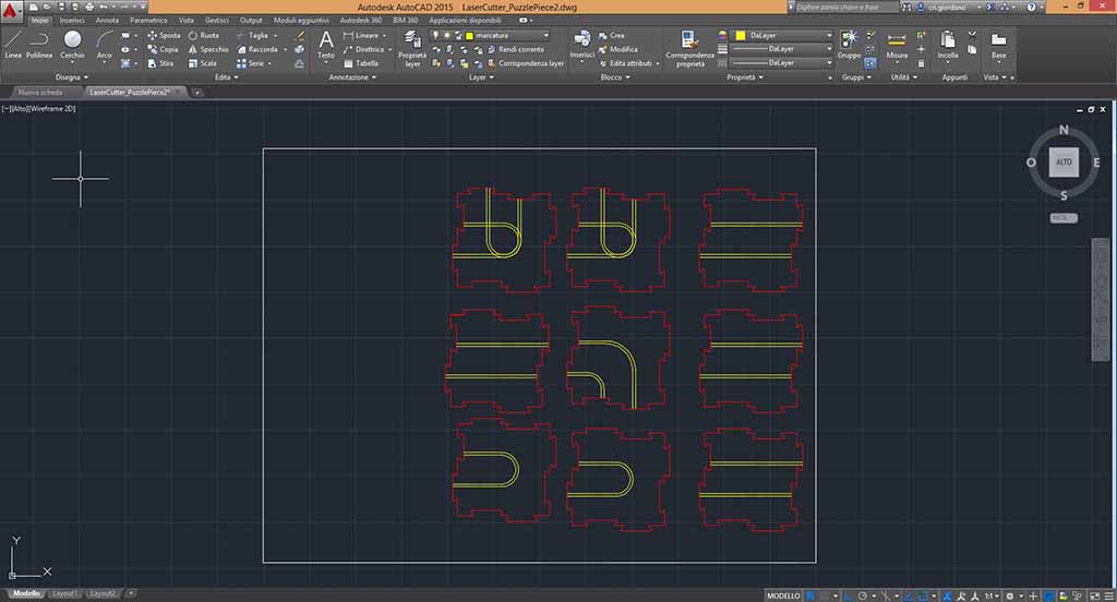
Laser cutter that I decide to use is SEI Eureka CO2 machine that has a working area of 600x450mm. So I draw a rectangle with these dimensions and I mark the lines that I want to cut from those I want to curve through two separate layers (Fig. 18). Finally I export my drawing in .dxf LT2000 because the ICARO proprietary software accepts only .dxf files.
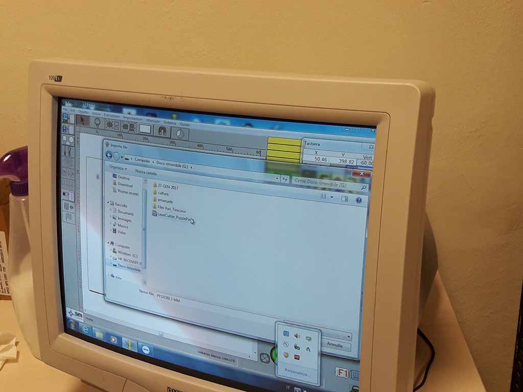
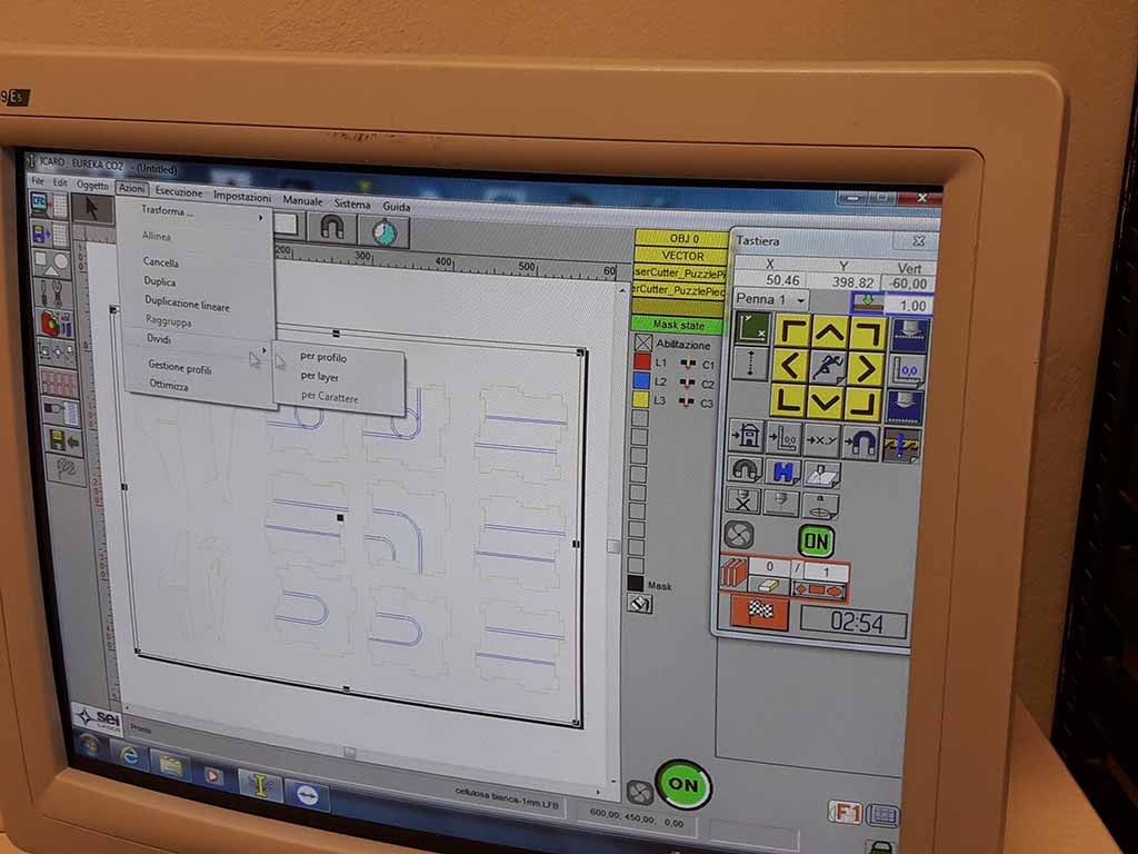
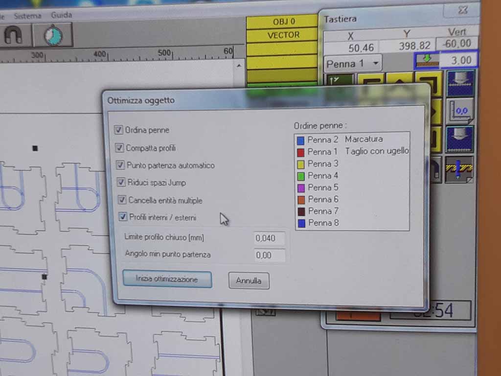
First of all I have to import my dxf file in laser cutter software (Fig. 19), so I can separate my layer, cancel the external rectangle, define the layer (Fig. 20) and optimize the drawing (Fig. 21).
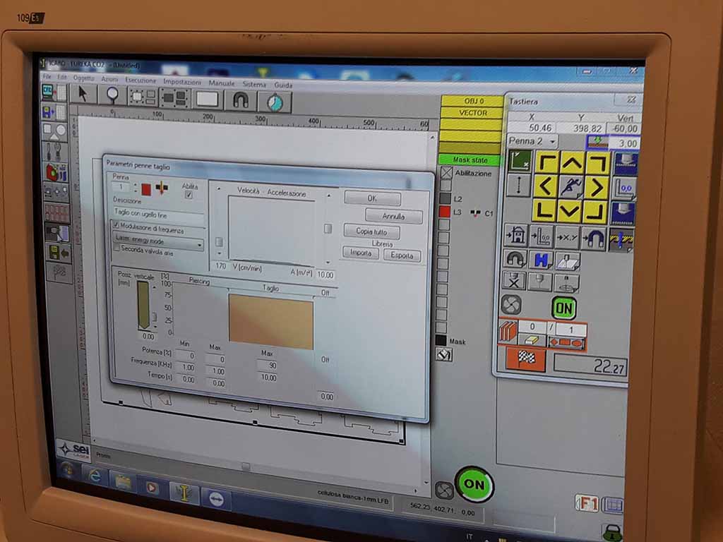
To have a good cut I used this parameters:
- Heading speed: 170 cm/min
- Heading acceleration: 10 m/s^2
- Laser cut setup: power 90% and frequency 10 KHz
The kerf machine is 0.4 mm with a 3 mm cardboard. To test the kerf I designed different width of the joints:
- 0.0 left half kerf and 0.0 right half kerf.
- 0.2 left half kerf and 0.2 right half kerf.
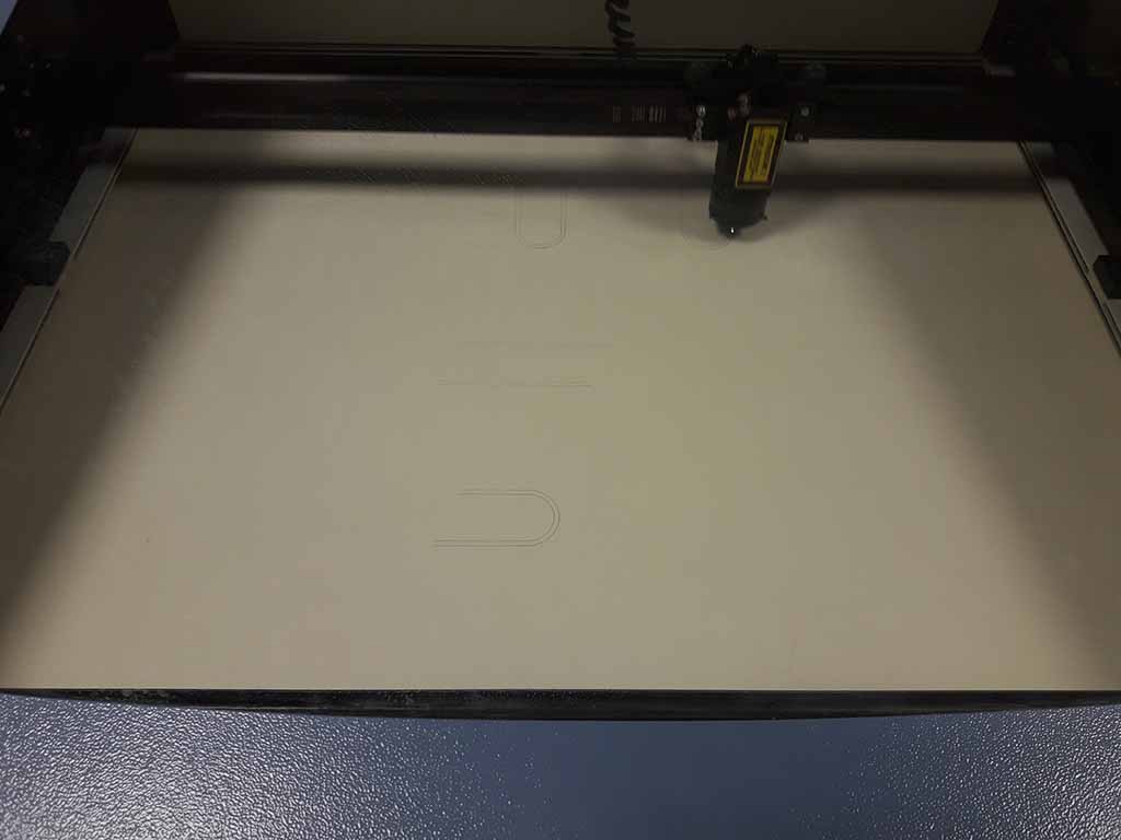
Before to start laser marking I have to remove the cutting from my machine, then I can select the marking layer, set up “Laser pulse mode” with “3 mm” for the marking and click on “Ok” (Fig. 22). The marking starts (Fig. 23).
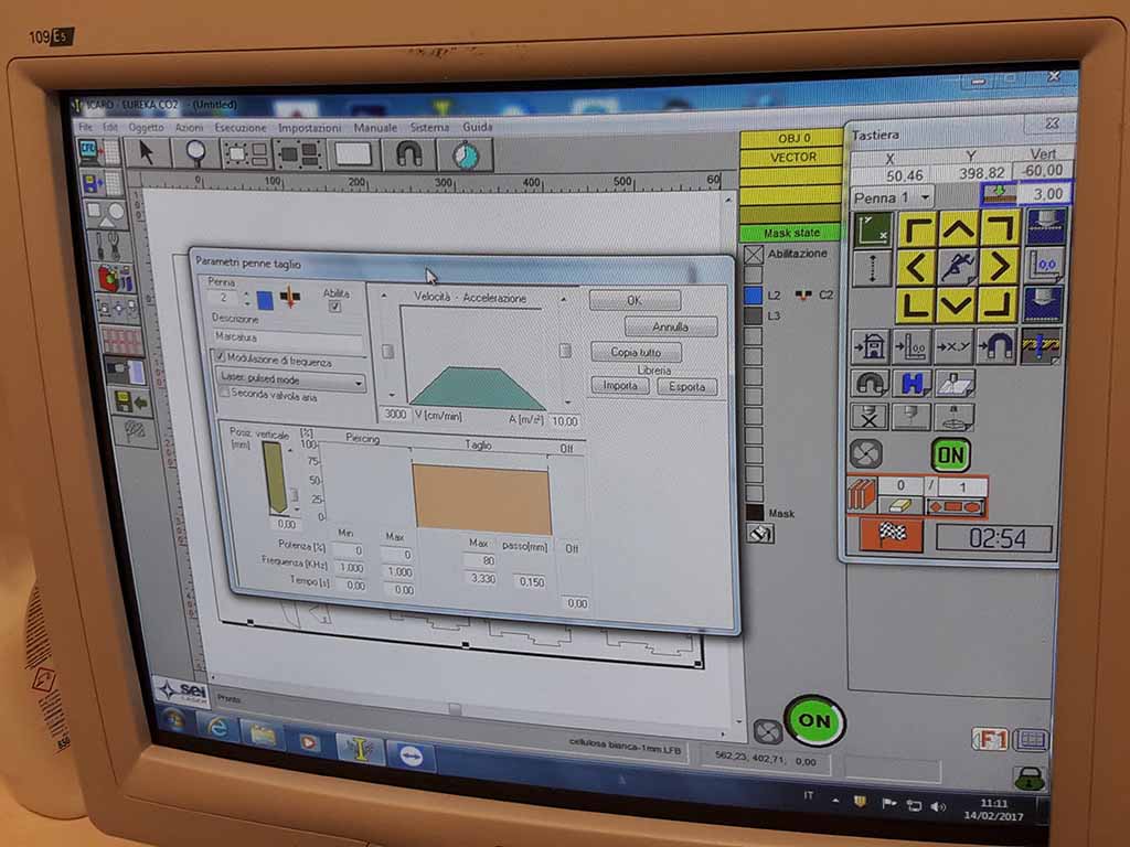
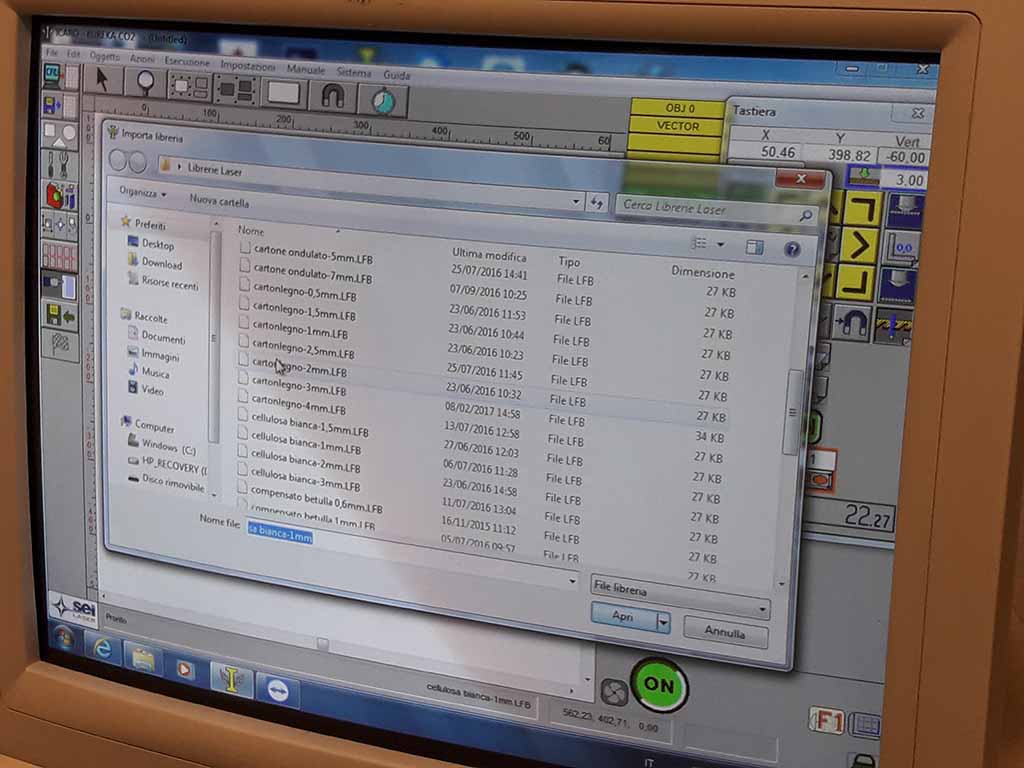
At this point I can select the cutting layer, import my material from library or set up for cardboard of 3 mm (Fig. 24) and click on “Ok” (Fig. 25). The cutting starts (Fig. 26).
When the machine finishes I can open the cover and remove the cardboard (Fig. 27).
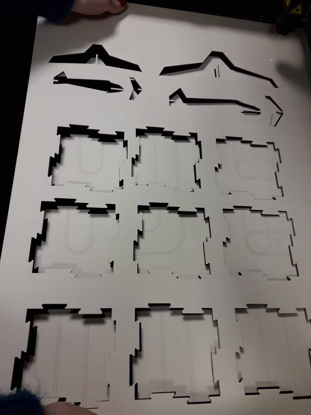
Now I can play with my puzzle (Fig. 28)!
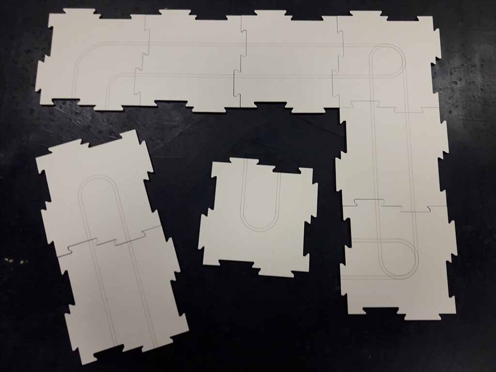
The joints must be lose so I suggest you to not increase cutting thickness during the drawing phase (0.0 left half kerf and 0.0 right half kerf). In fact the puzzle pieces can be mounted several times and with different combinations, so a little joints' space helps the the player during this activity. In addition, if the joint is perfectly precise (0.2 left half kerf and 0.2 right half kerf), the pieces may break.
Opendot Laser cutting setting
I laser cut more pieces for my final project and you can find them here. I wrote below the settings I used for laser cutting my final project.
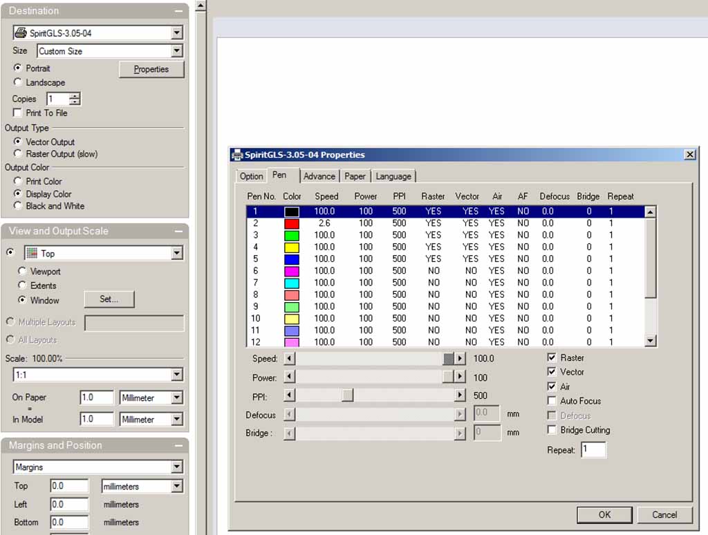
At Opendot I used the GCC SpiritGLS passing through Rhino. The work area for GCC SpiritGLS is 960x610 mm. I designed my drawing using Autocad and then I imported the .dxf file into Rhino. On Rhino I created two different layers, one for cutting on one for engraving. The machine cut first the black layer, then the red layer and last the green layer. For each layer you can set "speed" and "power" in the print setup (Fig. 29). It is better to use the black layer for engraving and the red layer for cutting.
For my final project I cut 3 mm MDF and 3 mm Plexiglass. Before I had a good cut, I tested different settings for different materials.
Remember to: calibrate the focus when you change the material (I used the automatic focus calibration) to turn on the fume extractor before to launch the cut file.
To have a good test, I suggest you to design and cut two little rectangle, one black (engrave) and one red (cut), before. In this way you will waste less material if the parameters are not right.
After some attempts, I can suggest this parameters for
Cutting 3 mm MDF:
- Speed: 2,5
- Power: 100
Engraving 3 mm MDF:
- Speed: 60
- Power: 60
Cutting 3 mm Plexiglass:
- Speed: 3
- Power: 100
If you want to see the photo of my final project and download my .dxf file, you can go on my final project development page.
How to use the vinil cutter
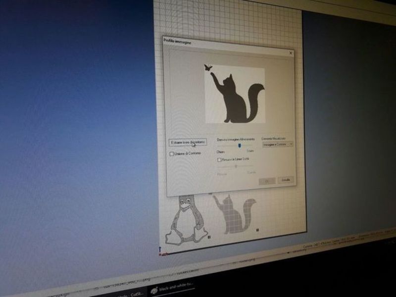
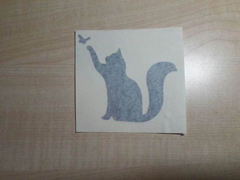
I have cut my first vinyl design at OpenDot using their Roland cutter and the proprietary software CutStudio. With the vinylcutter you can cut text, drawings and simple lines. Obviously, I have chosen the silhouette of a cat :-) After a quick search on Google for black and white cat images, I selected a nice on with a cat and a butterfly (Fig. 30).

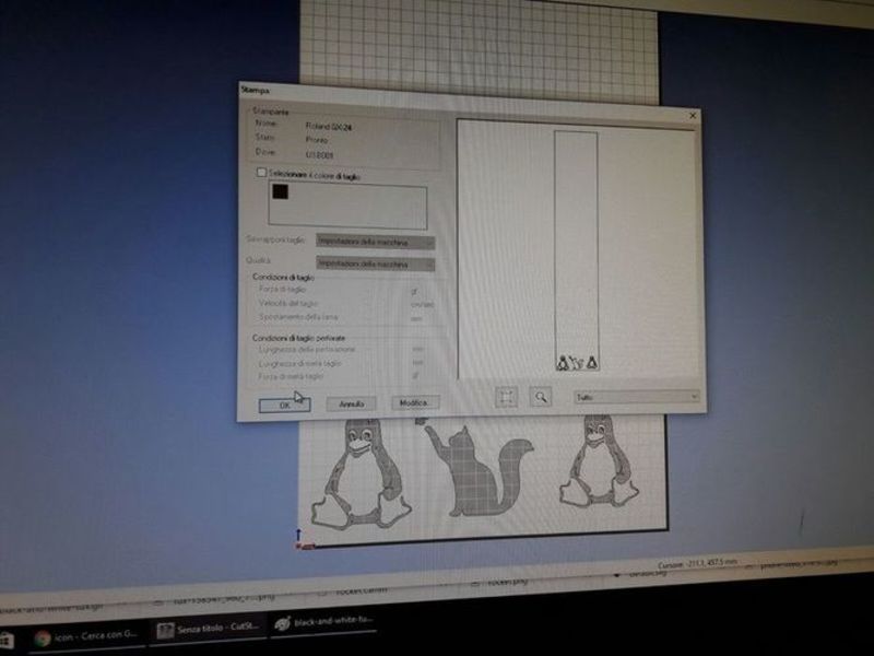
I have imported the image in CamStudio and then I have extracted the border using the tool "Image profile" already included in the program. Then, you can rotate and move the image wherever you want in the vinyl sheet: I have put it in the bottom of the screen (which is the beginning of the vinyl sheet) next to the designs of Emanuele and Pablo (Fig. 31).
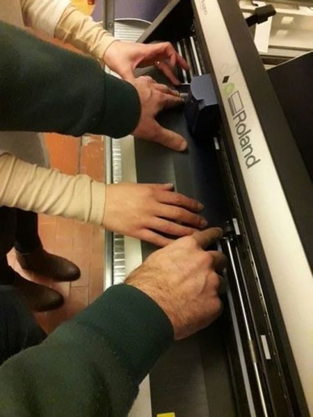
Then I have loaded the vinyl tape roll taking care of the margins (marked with a white sign on the cutter). You can choose the color you like: I used the blue one, but many others were available at OpenDot and I will play with them in the future (Fig. 32)!
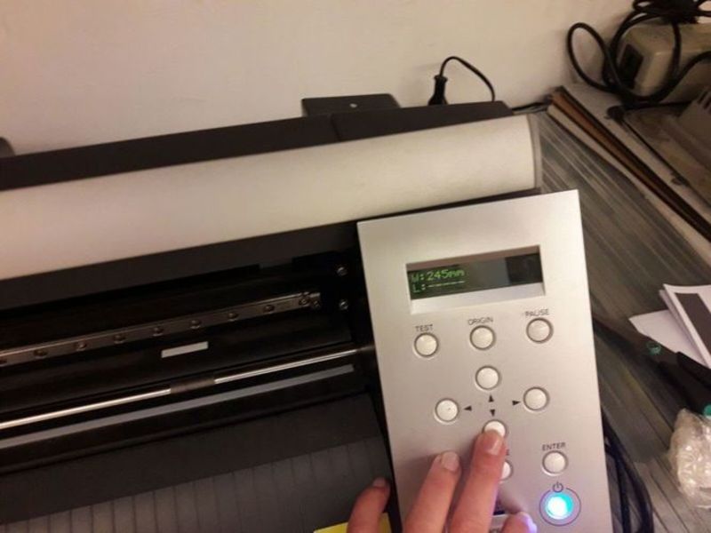
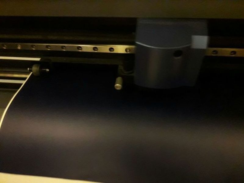
Next, I have turned on the cutter: at statup, the Roland cutter moves the heading forth and back and it automatically identify the width of the loaded sheet. The identified value is shown on the display (Fig. 33).
CamStudio should recognise the cutter connected through the USB port - this is my case, so I run the cut (Fig. 34).
The cutter started to load the vinyl sheet and cut it. It was very quite and fast, and it finished all the designs in a few minutes (Fig. 35).
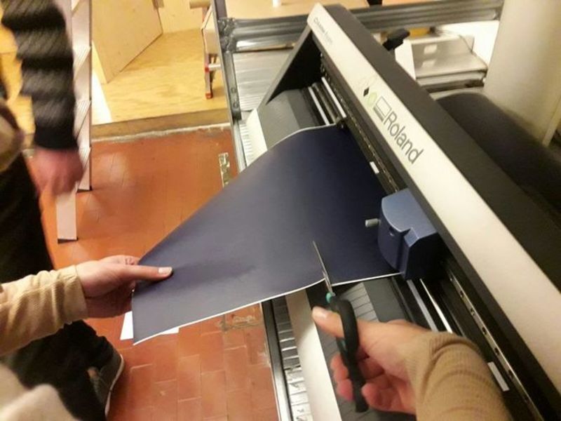
I cut away (by hand with scissors, not with the cutter) the design and moved to the table for the second part of the activity (Fig. 36).
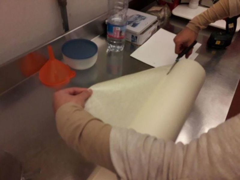
I have also cut a small piece of transfer paper. You need the transfer paper to pick the vinyl design away and move it to the destination surface. You could move simple designs, like my cat, without the transfer paper, peeling it like a normal sticker. However, this would be practically impossible with intricate designs (Fig. 37).
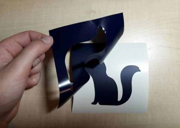
With the help of a small cutter, I have weeded all the vinyl around the cat and the butterfly, leaving the silhouette of the animals. By the way, I could have done the opposite (by taking out the animals) to use as it a stencil (Fig. 38).
I put the transfer tape on the vinyl and, with the help of a credit card, I have scraped over the design firmly to be sure that the transfer paper was adhering to the vinyl design (Fig. 39).
At this point you are ready to trasfer the design. You just need to peel it up, leaving the vinyl on the transfer tape, and apply it wherever you want pressing firmly. Finally, peel back the transfer tape slowly and the vinyl design should stay on the target surface.
Vinyl cutting setting
I vinyl cut more drawings that I have designed for my final project using the Roland Stika SV-12 available at FabLab Mantova and you can find them here.
The cutting speed of the Roland Stika is between 12 and 40 mm/sec. This value can be changed from clicking File menu, then Cutting Setup. The Cutting Setup screen appears: click Properties and then the Settings tab (Fig. 40).
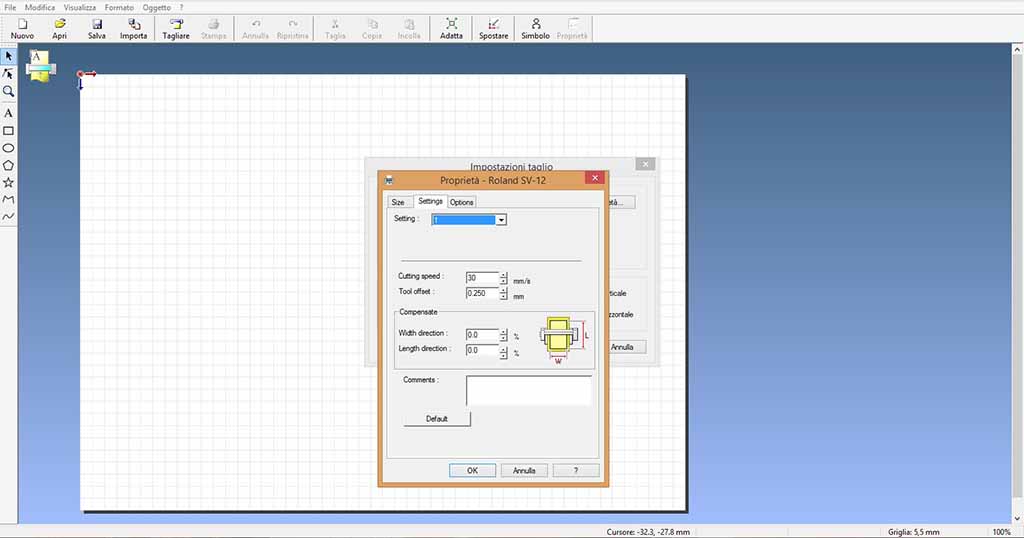
I left the default speed of 30 mm/s, which seemed a good compromise between a precision and velocity.
According to the manual, Roland is able to cut Vinyl chloride material having a thickness is 0.1 mm or less and an overall thickness of 0.3 mm or less (including the backing paper). The material cutting quality is controlled by the blade extension amount. If the material is difficult to peel from the backing paper or, on the contrary, the blade trace is indistinct, it means you have to adjust the blade position either retracting or extending it.
A rough configuration of the blade extension requires manual intervention. As you can see below (Fig. 41), you have to loosen the screw, remove the blade holder and adjust the blade extension amount turning the tip of the blade holder.
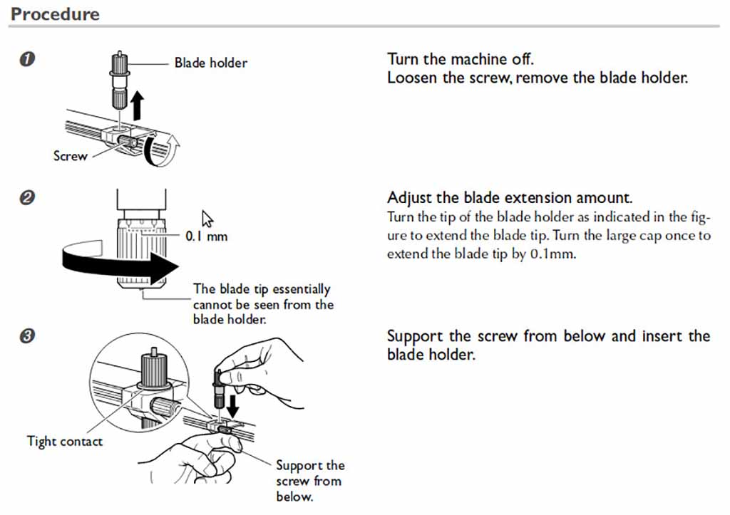
A rough estimate for setting the amount of blade extension is provided by Roland as the sum of the Vynil thickness plus half the thickness of the backing paper. This should create faint lines on the backing paper without actually cutting it.
In the Settings tab shown above you can also compensate the tool offset if you need to do minor compensation to the position of the blade without moving it manually. The default value is 0.25 mm and I left this value untouched because the quality of the cut was fine: I was able to peel of perfectly all the designs without troubles.