What is Embedded Networking and Communications ?
Embedded Communication
Embedded communication means transport of information from one circuit to another circuit. Where the circuit which transmits the data is called Transmitter and the circuit who receive the data is called Receiver. Atleast one Transmitter and a Receiver is required to establish the communication. Communication may be in one direction or in both directions, there are different classifications according to this, basic classification is Synchronous and Asynchronous communication. If breifing about this in one sentence, Synchronous means: sender and receiver use the same clock signal and Asynchronous Means: sender provides a synchronization signal to the receiver before starting the transfer of each message.
Data communications refers to the transmission of this digital data between two or more micro contollers/computers is called Networking and Communication.
Communication Protocols
A communication protocol is a system of rules that allow two or more entities of the communications system to transmit information via any kind of variation of a physical quantity. Communications protocols cover authentication, error detection and correction, and signaling. They can also describe the syntax, semantics, and synchronization of analog and digital communications. Communications protocols are implemented in hardware and software. There are thousands of communications protocols that are used everywhere in analog and digital communications.
Some of importatnt protocols
I²C
Inter-Integrated-Circuit-bus or Two-wire serial bus: Used to connect ICs on a single board. The bus has one clock and one data line. Both the clock and data line are pulled high and device only drives the lines low. There are plenty of ICs available with build-in I²C interface including many of the modern µcontrollers. µcontrollers with build in I²C support:
RS232
Recommended Standard 232: Better known as the serial port on a PC. Used to connect two devices.RS422
Recommended Standard 422: industrial version of RS232. Much better than RS-232 at resisting interference.CAN
Acronym stands for "Controller Area Network." More complicated network. Used in automotive and domotica. Originally developed by Bosch in Germany. Limited to 1 Mbps in theory; with required overhead, protocol is slower than 1 Mbps. Data is delivered in packets of 8 bytes. CAN is frequently referred to as CANbus.SPI
SPI(Serial peripheral interface) is a 4-wire full duplex bus. The bus has a clock, transmit, receive, and select line. One device controls communication on the bus. When connecting multiple devices, each device is connected to the master with a separate select line and the master selects only one device at a time.1wire
This bus uses 1 wire to supply power and communication to a IC. Used for temperature sensors and other low-power ICs. Despite the name, a second wire, ground, is used to complete the circuit. Data is sent to the IC by switching the wire between high and low. A built-in capacitor provides the IC with power during the low parts of the signal. This bus is intended for low-power devices, like temperature sensors.Workflow of making Master ,salve boards and construction
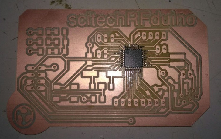
i have decided to make the boards using the nRF communication to triger the condition and want to use the nRF to get the data so i have decided to make the my board named scitechRFduino
What is nRF24L01
The nRF24L01 is a highly integrated, ultra low power (ULP) 2Mbps RF transceiver IC for the 2.4GHz ISM (Industrial, Scientific and Medical) band. With peak RX/TX currents lower than 14mA, a sub μA power down mode, advanced power management, and a 1.9 to 3.6V supply range, the nRF24L01 provides a true ULP solution enabling months to years of battery lifetime when running on coin cells or AA/AAA batteries.
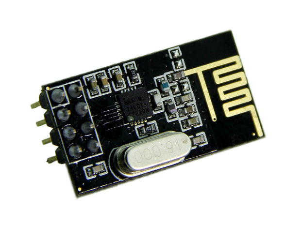
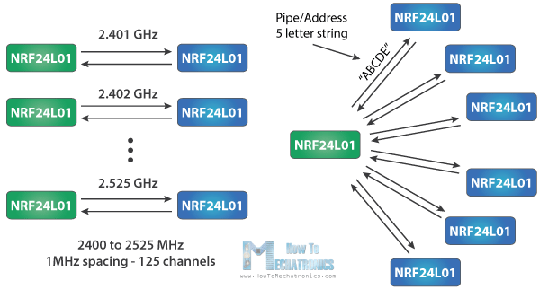
The module can use 125 different channels which gives a possibility to have a network of 125 independently working modems in one place. Each channel can have up to 6 addresses, or each unit can communicate with up to 6 other units at the same time.
The power consumption of this module is just around 12mA during transmission, which is even lower than a single LED. The operating voltage of the module is from 1.9 to 3.6V, but the good thing is that the other pins tolerate 5V logic, so we can easily connect it to an Arduino without using any logic level converters.
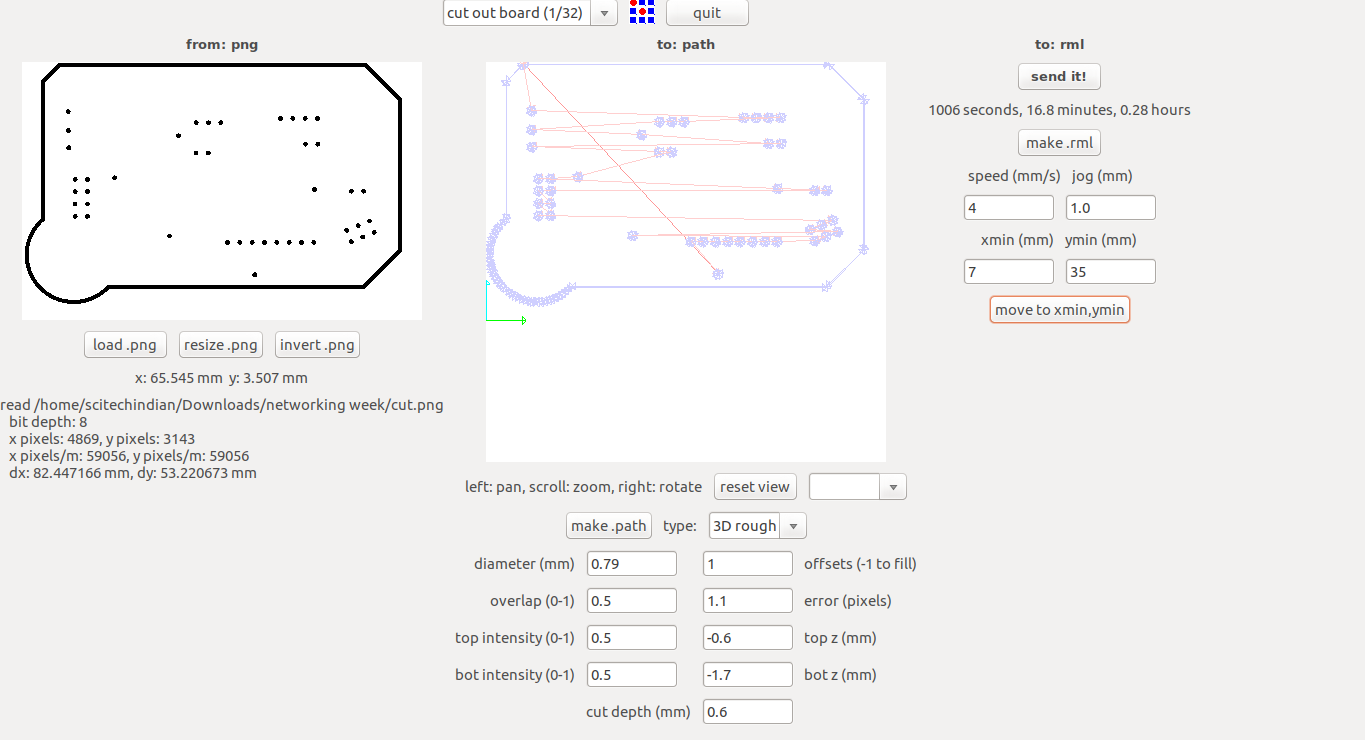
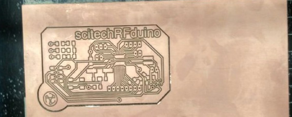
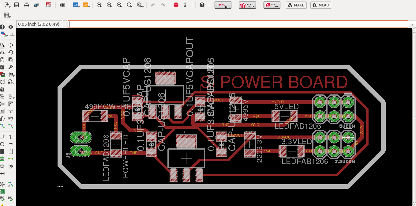
Production of the Scitechduino
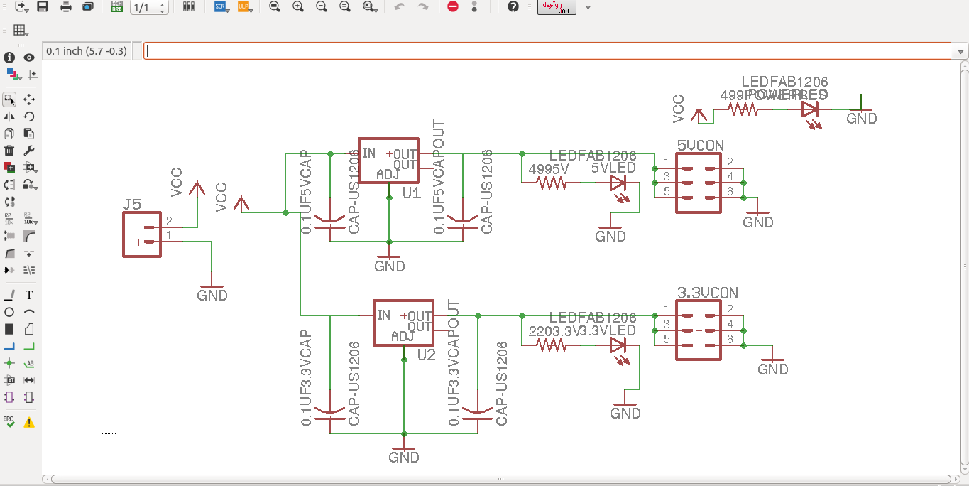
As i am good with electronic design using the eagle software this week also ,i have used the eagle to design my scitechRFduino
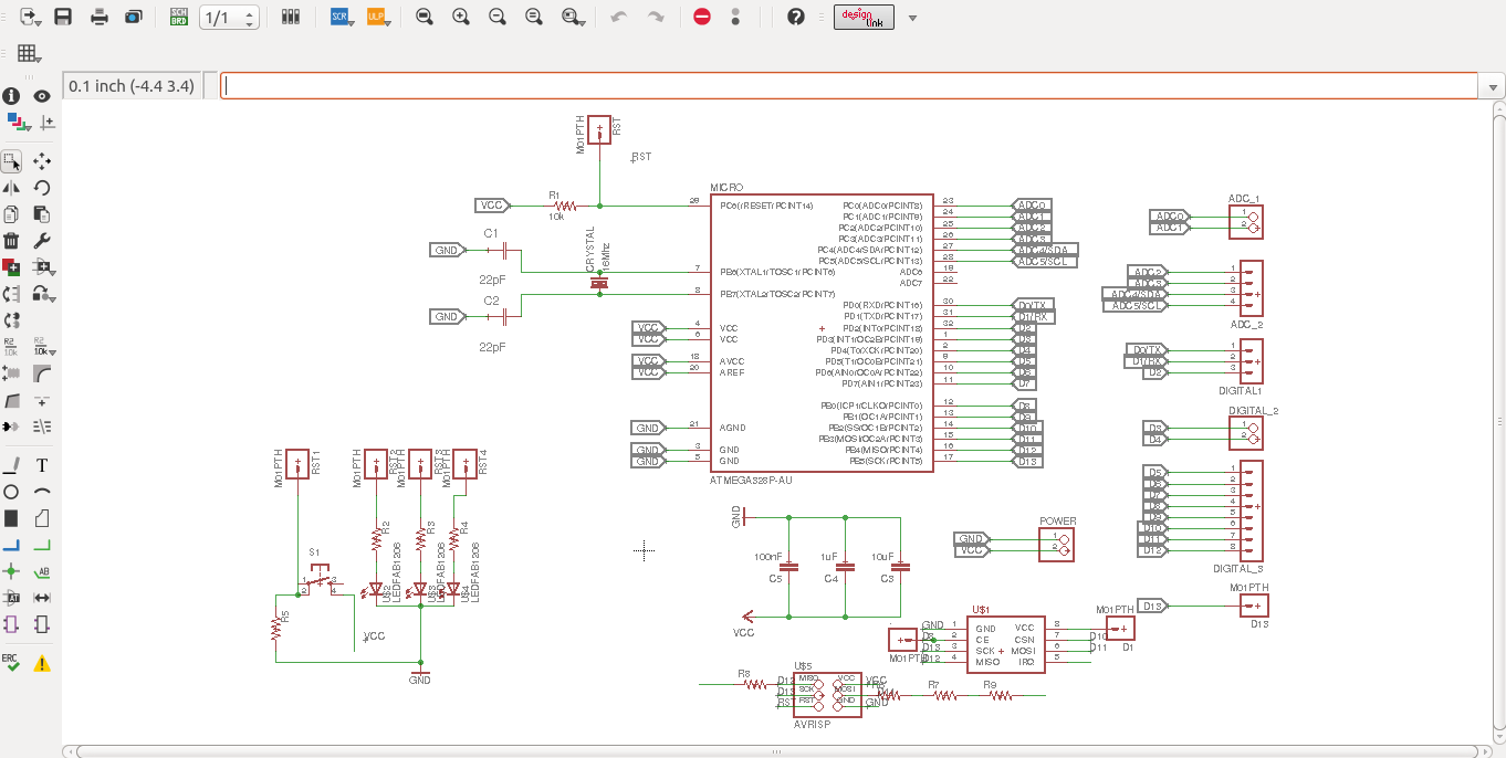
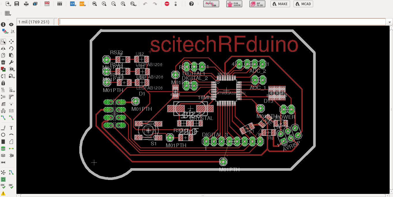
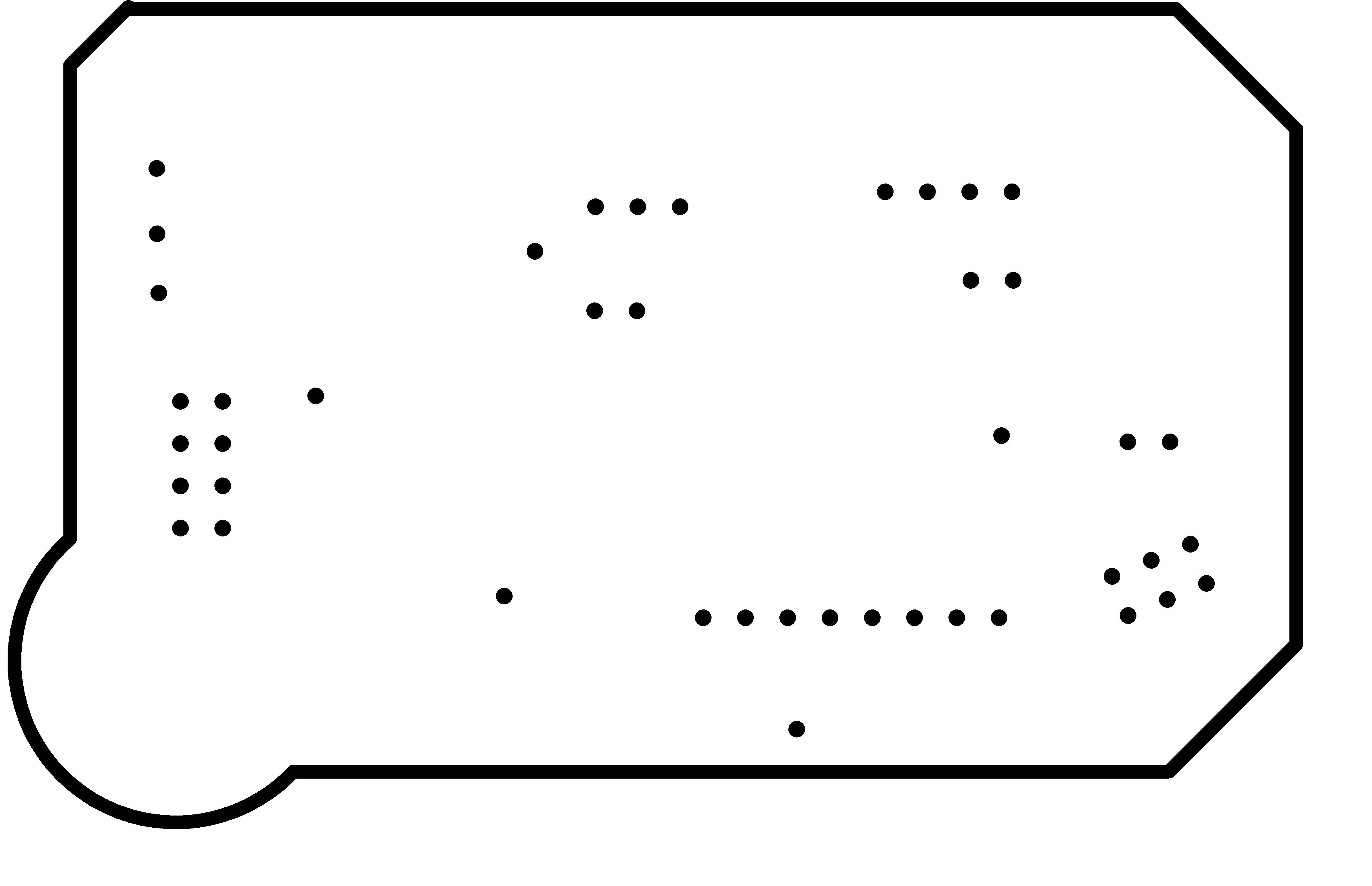
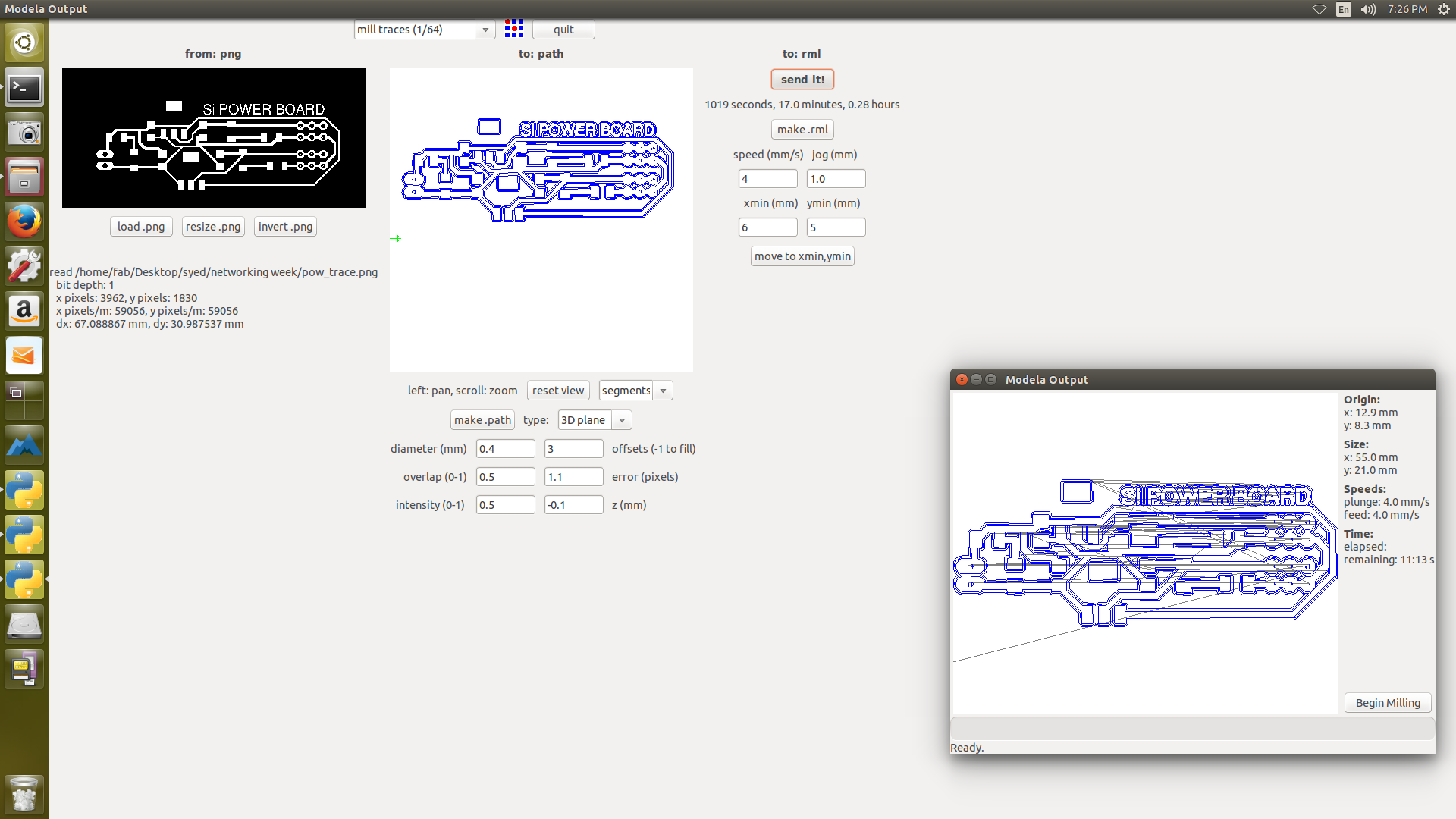
The design files exported to the png format to make the board using the modela same as Electronics Production


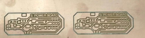
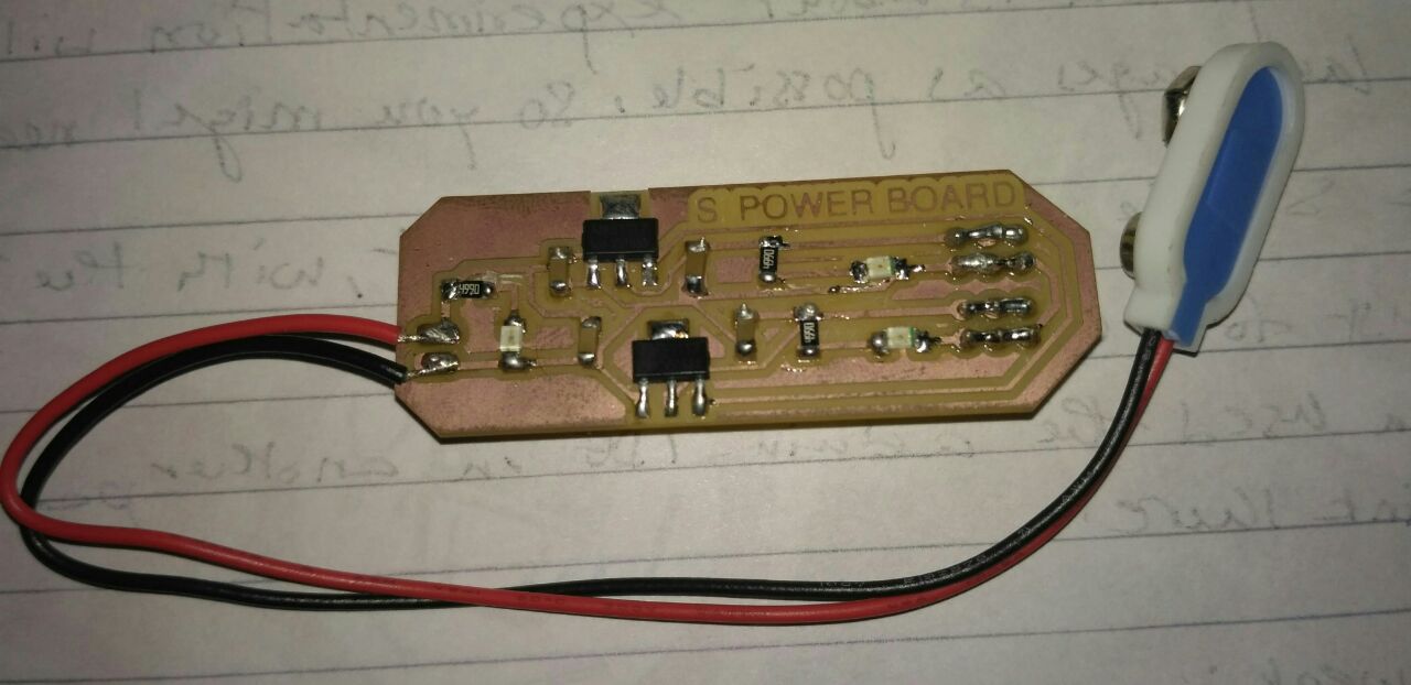
for the nRF we need a 3.3v power sourcee as input and for powering up you need a 5v current and so i have decided to make a power board for it separtely
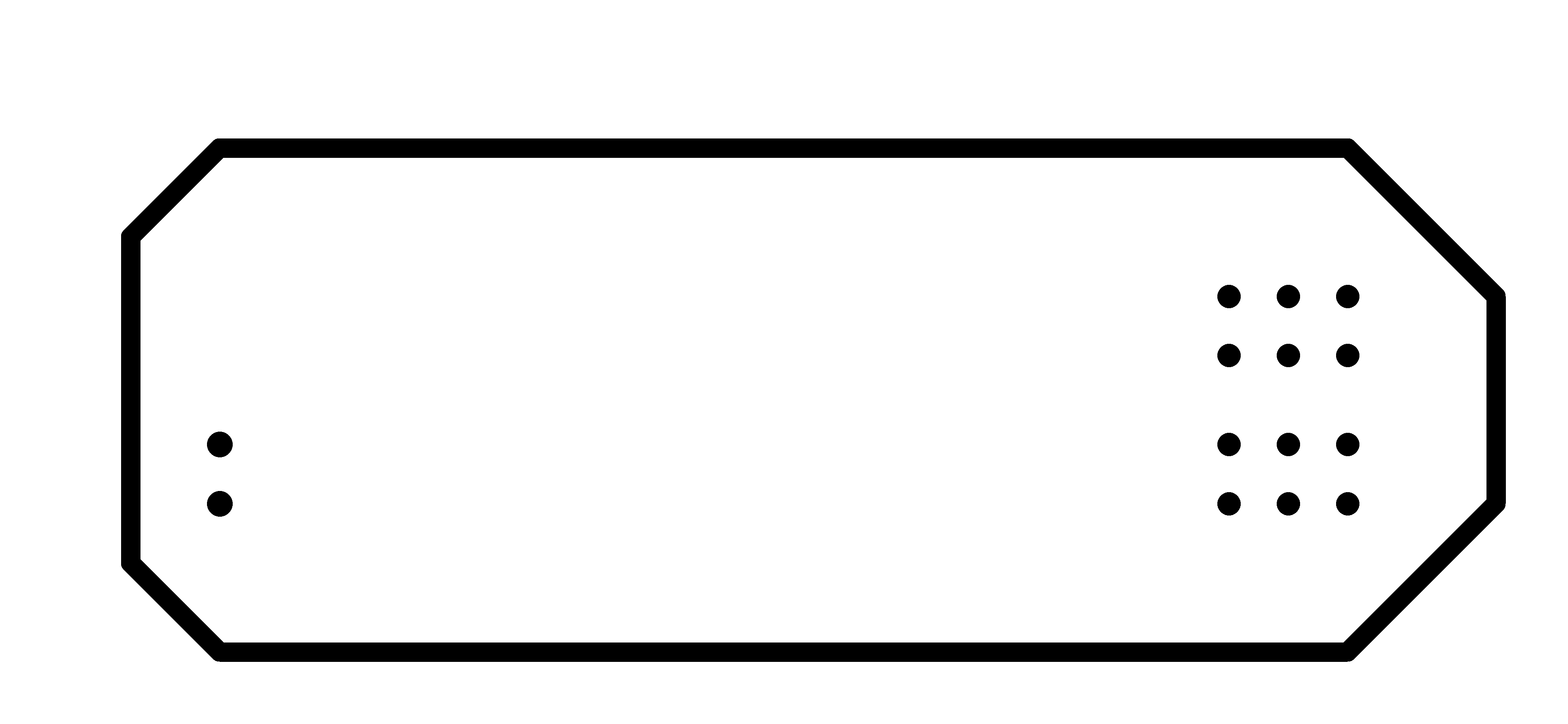
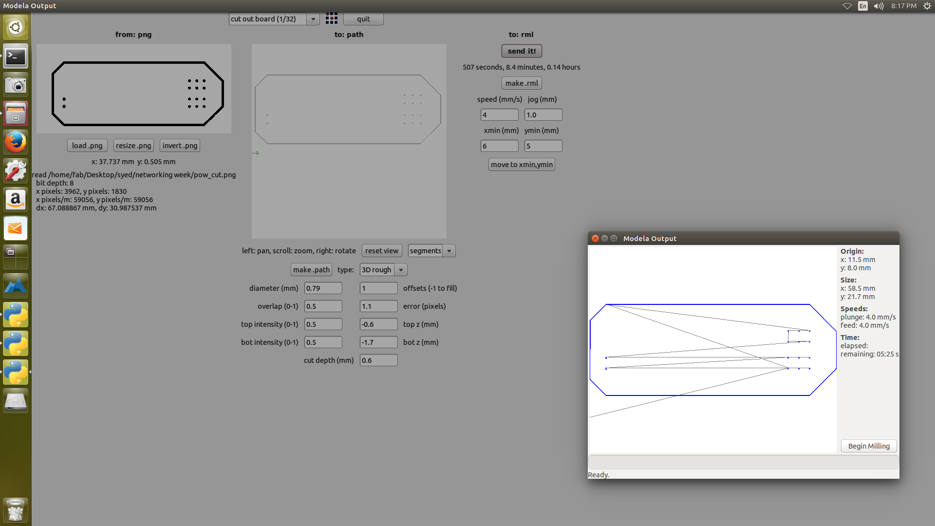
Milled the power board using the modella

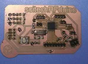
Now soldering of these boards
Soldering of boards
as this now we are at week16 i have got good at the soldering skills so i have made the two boards soldering very fastly
programming and output
Programming for the communication between the two boards with nRF Communication one as the transmitter and other as the reciver ,i have used the pin connections to nRF24L01 pin connection is as follows (note that you may need to connect it differently if you use a different arduino board, refer to the RadioHead library):
the connection of the switch on the transmitter is connected to the D7
the connection of the led on the reciver is connected to the D3
all the pins are according to arduino pinouts
code for the transmitter
- #include <SPI.h>
- #include "nRF24L01.h"
- #include "RF24.h"
- int msg[1];
- RF24 radio(8,10);
- const uint64_t pipe = 0xE8E8F0F0E1LL;
- int SW1 = 7;
- void setup(void){
- Serial.begin(9600);
- radio.begin();
- radio.openWritingPipe(pipe);}
- void loop(void)
- {
- if (digitalRead(SW1) == HIGH)
- {
- msg[0] = 111;
- radio.write(msg, 1);
- }
- }
code for the Receiver
- #include <SPI.h>
- #include "nRF24L01.h"
- #include "RF24.h"
- int msg[1];
- RF24 radio(8,10);
- const uint64_t pipe = 0xE8E8F0F0E1LL;
- int LED1 = 3;
- void setup(void){
- Serial.begin(9600);
- radio.begin();
- radio.openReadingPipe(1,pipe);
- radio.startListening();
- pinMode(LED1, OUTPUT);}
- void loop(void){
- if (radio.available()){
- bool done = false;
- while (!done){
- done = radio.read(msg, 1);
- Serial.println(msg[0]);
- if (msg[0] == 111){delay(10);digitalWrite(LED1, HIGH);}
- else {digitalWrite(LED1, LOW);}
- delay(10);}}
- else{Serial.println("No radio available");}}
Output
i was able to on the LED on the reciver using the transmitter
Hero Shot
Now here we comes to the Hero Shot of this Week
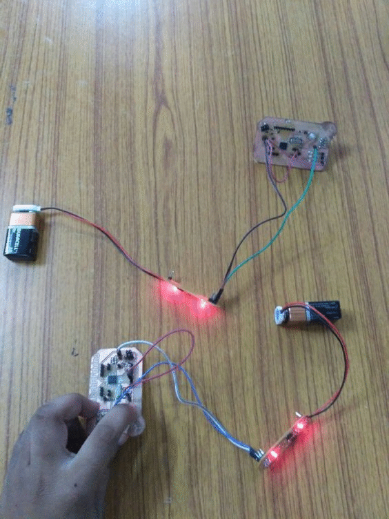
Implimentation of Embedded Networking and Communications week design
