Tenth Assignment:
Contents:
Requirement:
- Eagle software.
- Milling machine.
- Electronics components.
- Welding station.
- A AVR o FabIsp Programmer.
For this assignment I have to add an output device to a microcontroller board I've designed and program it to do something
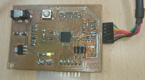
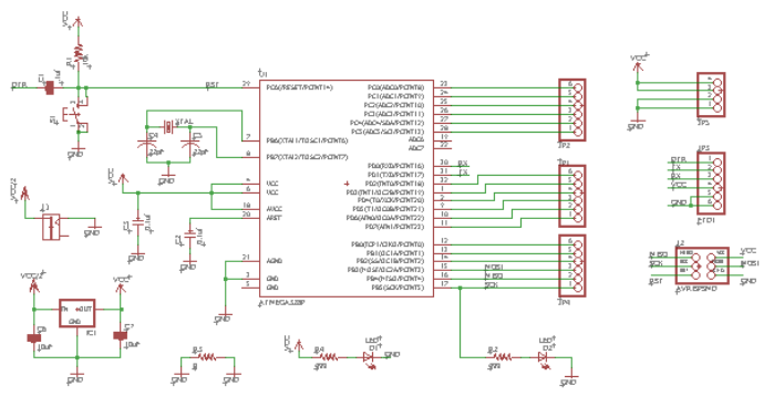
Design my own Aduino Board: FabDuino
Microcontroller board that I decided to design was a Fabduino Board,
 |
|---|
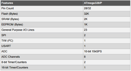
This board use Atmega 328p microcontroller, and is necessary to know more about microcontroller, for that reason I have to read its data sheet, like embedded programming
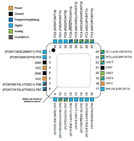
Microcontroler 328p Data sheet
Some caracteristics are show below
 |
 |
|---|
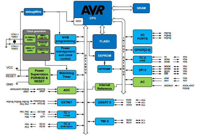
Bloc Diagram
 |
|---|
Read More: http://www.atmel.com/images/Atmel-8271-8-bit-AVR-Microcontroller-ATmega48A-48PA-88A-88PA-168A-168PA-328-328P_datasheet_Complete.pdf
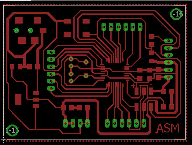
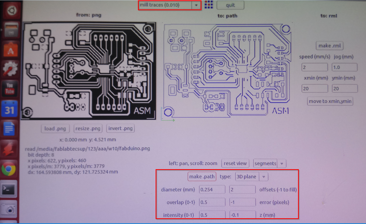
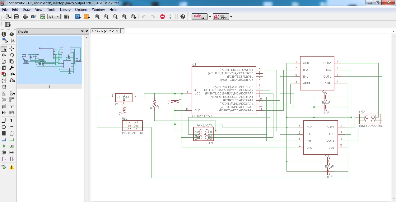
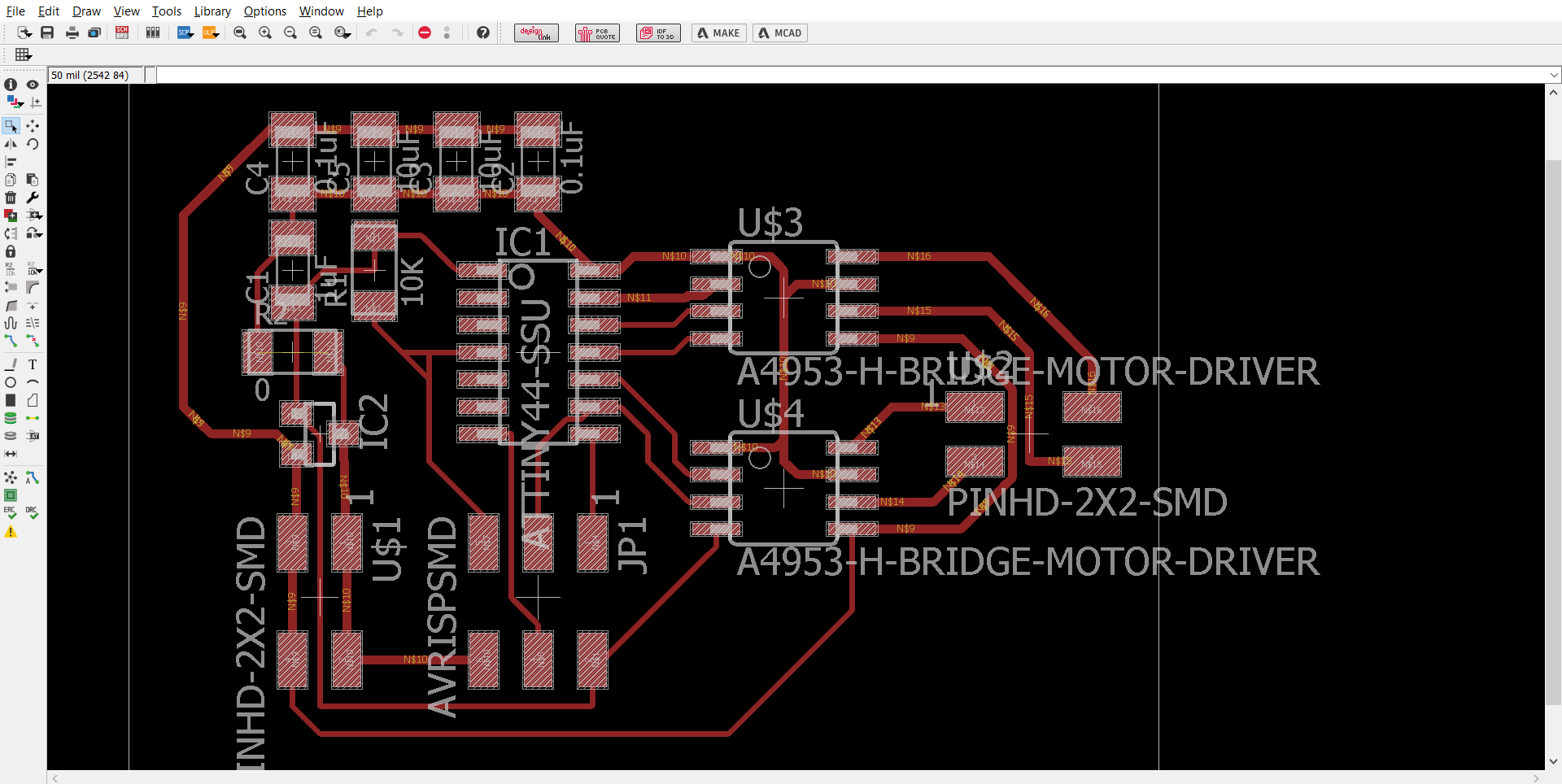
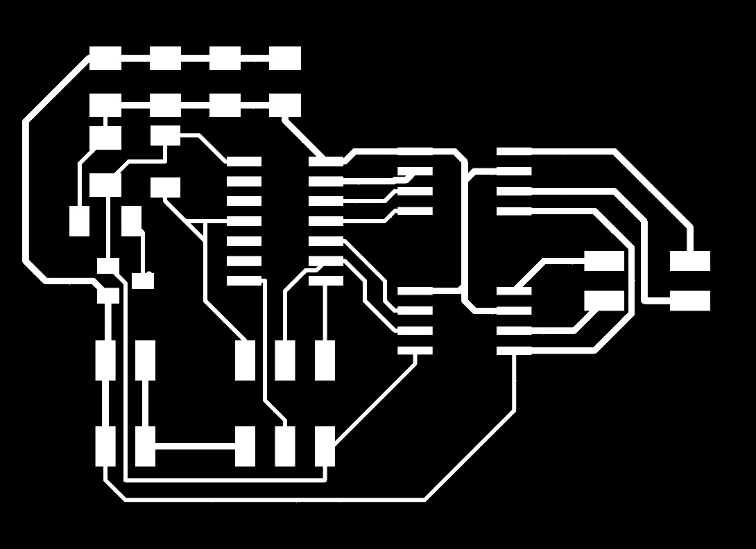
On software Eagle are schemamtic and board design, when you design is finish, you need to export as a Image and then using milling machine, Roland Modela Fablab Tecsup case, upload your file.
And the last step or FabDuino fabrication is welding their components
 |
 |
|---|
 |
|---|
On assignment 4, I explain how to use a milling machine, in tecsup case has a ROLAND MODELA MDX-20
 Step Motor and driver a4988 Step Motor and driver a4988
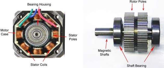
Step Motor
Stepper motors are DC motors that move in discrete steps. They have multiple coils that are organized in groups called "phases". By energizing each phase in sequence, the motor will rotate, one step at a time.
Read More: https://cdn-learn.adafruit.com/downloads/pdf/all-about-stepper-motors.pdf Driver a4988
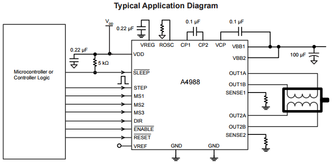
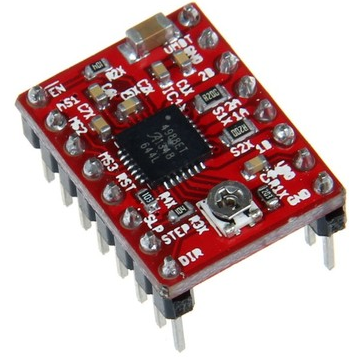
The A4988 is a complete microstepping motor driver with built-in translator for easy operation. It is designed to operate bipolar stepper motors in full-, half-, quarter-, eighth-, and sixteenth-step modes, with an output drive capacity of up to 35 V and ±2 A. The A4988 includes a fixed off-time current regulator which has the ability to operate in Slow or Mixed decay modes.
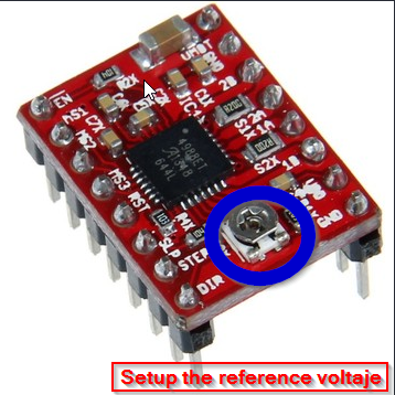
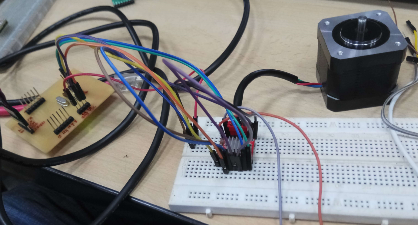
My stepper motor consumed high current, because i didn't set the reference voltaje with the potentiometer on the driver board.
Read More: https://www.pololu.com/file/download/a4988_DMOS_microstepping_driver_with_translator.pdf?file_id=0J450 Programming Microcontroler 328p
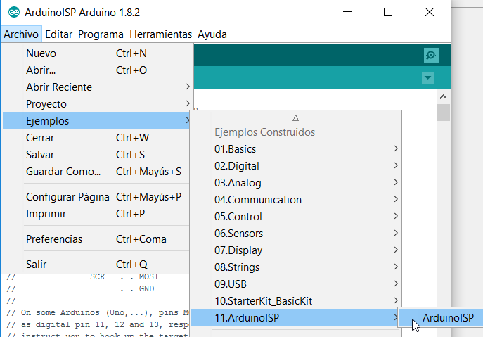
In this case also I will need to use Software Arduino IDE to programm my own Fabduino ( because it wors as a normal Arduino)
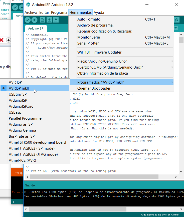
For this assignment I decided try the Atmel programmer AVRISP MKII
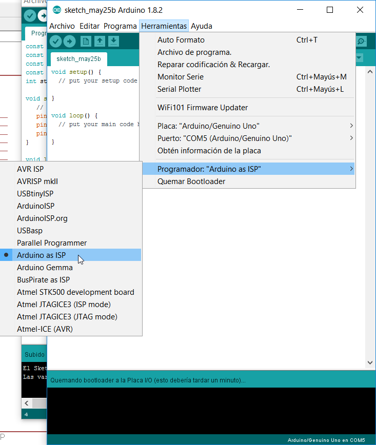
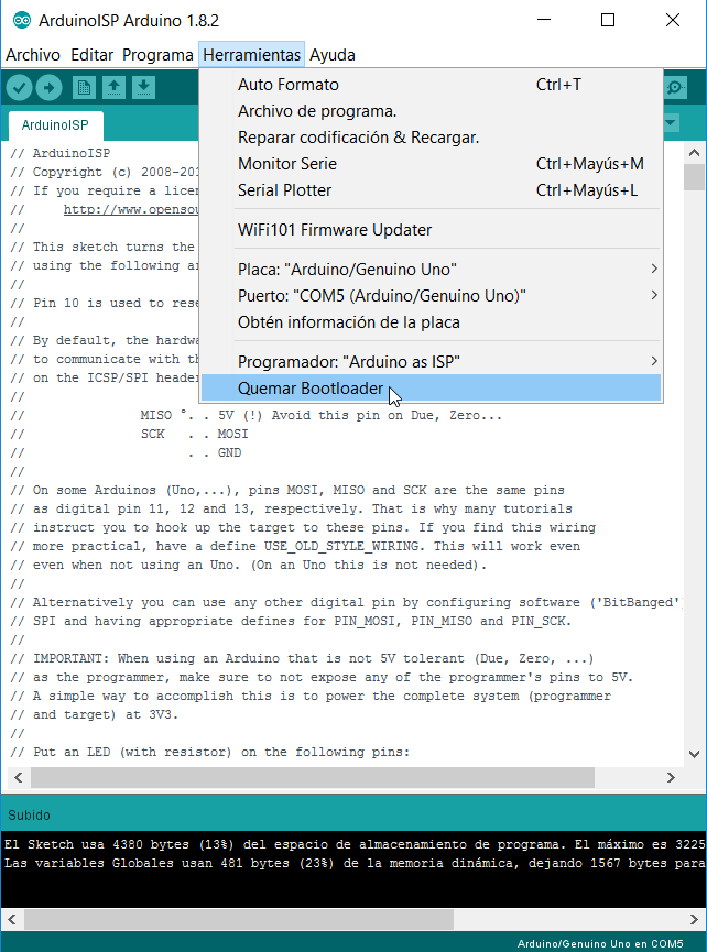
I used the programmer MKII to load the bootloader into my fabduino
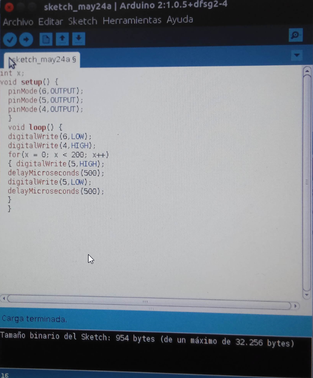
After, I loaded the program to controlled the step motor
Finally I test my program on my board
Design and build of my own step motor control card
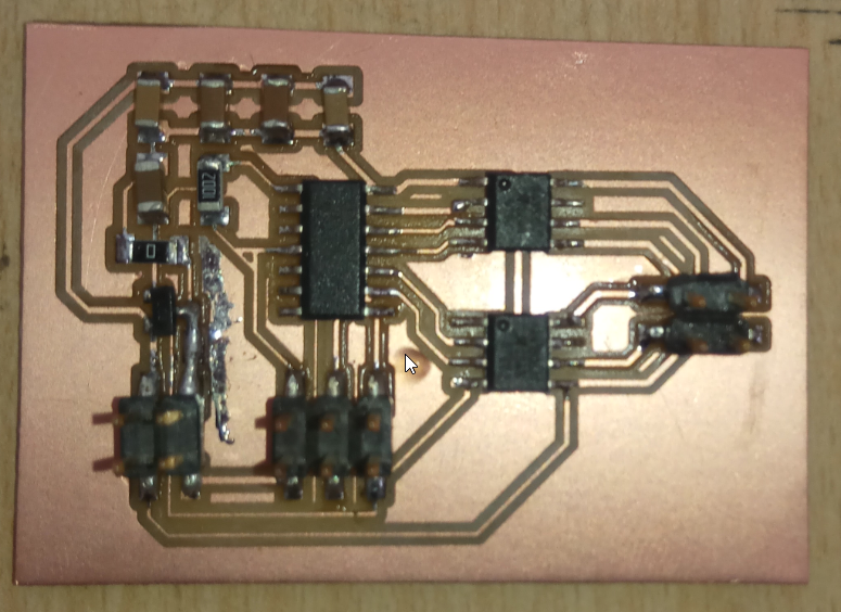
For this assignment I decide design and build my own motor driver controller, using a attiny44 as microcontroller and a A4953 H-Bridge motor driver, to control a bipolar step motor.
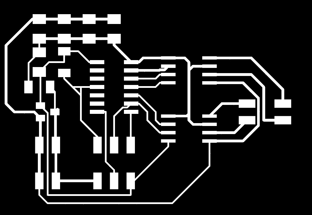
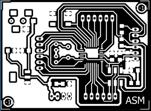
The second step is make the PCB, for this I used the Modela milling machine and this use a black and white high resolution PNG image.
This is my board milled and soldered
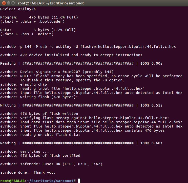
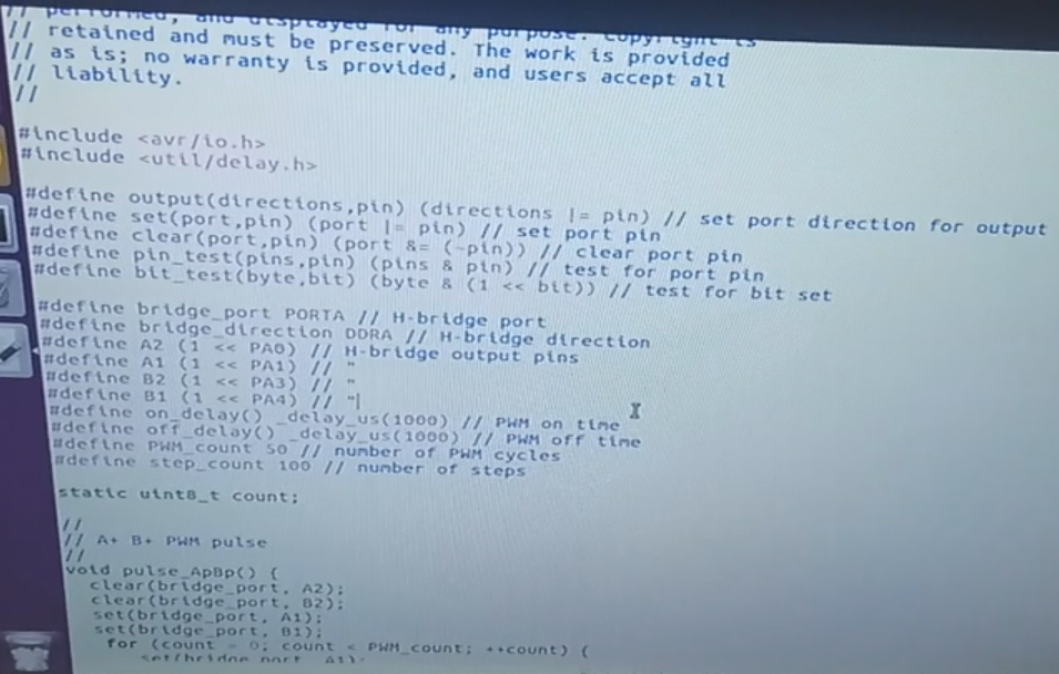
The next step was load the program to my PCB
Finally I did some tests Selft evaluation
File download
|
|---|